
Related Manuals for Fluke 7037


Summary of Contents for Fluke 7037
- Page 1 7037/7038/7040/7041 Calibration Bath User's Guide May 2016 © 2016 Fluke Corporation. All rights reserved. Specifications are subject to change without notice. All product names are trademarks of their respective companies.
- Page 2 Fluke authorized resellers shall extend this warranty on new and unused products to end-user customers only but have no authority to extend a greater or different warranty on behalf of Fluke. Warranty support is available only if product is purchased through a Fluke authorized sales outlet or Buyer has paid the applicable international price.
-
Page 3: Table Of Contents
Page Before You Start ..................1 Symbols Used ................... 1 Safety Information ................2 Cautions .................... 5 How to Contact Fluke Calibration ............6 Product Introduction ................7 Specifications ..................8 Environmental Conditions ..............9 Quick Start ..................... 9 Unpacking ..................9 Set Up .................... - Page 4 7037/7038/7040/7041 User's Guide Fluid Lifetime ................. 23 Safety .................... 23 Cost ....................24 Commonly Used Fluids ..............24 Fluid Characteristics Charts ............25 About the Graph ................25 Stirring ....................29 Power ....................29 Heater ....................29 Cooling ....................30 Temperature Controller ..............
- Page 5 Contents (continued) Measuring the Set-point Error ............51 Computing R and ALPHA ..............52 Calibration Example ................52 Maintenance ..................53 Troubleshooting ..................55 Troubleshooting Table ............... 55 Comments ..................58 EMC Directive ................58 Low Voltage Directive (Safety) ............59...
- Page 6 7037/7038/7040/7041 User's Guide...
- Page 7 List of Tables Table Title Page Symbols ..................... 1 Table of Various Bath Fluids and their Properties ........26 Proportional Band- Fluid Table ..............37 Interface Command Summary ..............47 Serial Power Control Functions ..............50 Remote Operation Ranges and Settings ........... 51...
- Page 8 7037/7038/7040/7041 User's Guide...
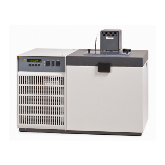
- Page 9 List of Figures Figure Title Page Bath Assembly ..................7 Front Panel ....................16 Refrigeration Side Panel Controls ............. 17 Back Panel ....................19 Drain Location and Lid Options ..............21 Chart of Various Bath Fluids and their Properties ........28 Controller Operation Flow Chart ..............
- Page 10 7037/7038/7040/7041 User's Guide viii...
-
Page 11: Before You Start
Before You Start Symbols Used Table 1 lists the International Electrical Symbols. Some or all of these symbols may be used on the instrument or in this manual. Table 1. Symbols Symbol Description WARNING. HAZARDOUS VOLTAGE. Risk of electric shock. WARNING - RISK OF DANGER. -
Page 12: Safety Information
7037/7038/7040/7041 User's Guide Conforms to European Union directives. Conforms to relevant Australian EMC standards. Fuse à Conforms to relevant South Korean EMC Standards. This product complies with the WEEE Directive marking requirements. The affixed label indicates that you must not discard this electrical/electronic product in domestic household waste. - Page 13 Calibration Bath Before You Start • Before initial use, or after transport, or after storage in humid or semi-humid environments, or anytime the instrument has not been energized for more than 10 days, the instrument needs to be energized for a “dry-out” period of 2 hours before it can be assumed to meet all of the safety requirements of the IEC 61010-1.
- Page 14 • Always replace the power cord with an approved cord of the correct rating and type. If you have questions, contact an Authorized Service Center. See the How to Contact Fluke Calibration section. • High voltage is used in the operation of this equipment.
-
Page 15: Cautions
Calibration Bath Before You Start Cautions WCAUTION • Always operate the instrument in room temperatures listed in the Environmental Conditions section. Allow sufficient air circulation by leaving at least 15 cm (6 inches) of clearance around the instrument. • DO NOT overfill the bath. Overflowing fluid may damage the electrical system. -
Page 16: How To Contact Fluke Calibration
Under and Over Voltage Protection at 230 VAC o Voltage Cutout: ±12.5% (203 - 257 VAC) o Voltage Cut In: ±7.5% (213 - 247 VAC) How to Contact Fluke Calibration To contact Fluke Calibration, call one of the following telephone numbers: • Technical Support USA: 1-877-355-3225 •... -
Page 17: Product Introduction
Digital remote communications is optionally available with a RS-232 or IEEE-488 interface. There are two lids available for the 7037 and 7040 baths; the standard lid with a rectangular access hole and an optional lid with a recirculation pump (see Figure 5). -
Page 18: Specifications
7037/7038/7040/7041 User's Guide Specifications Specifications 7037 7038 7040 7041 Operating Range –40°C to –10°C to –40°C to 110°C 110°C 110°C Stability ±0.002°C at -40°C (ethanol) ±0.0015°C at 25°C (water) ±0.003°C at 100°C (oil 5012) Uniformity ±0.004°C at -40°C (ethanol) ±0.002°C at 25°C (water) ±0.004°C at 100°C (oil 5012) -
Page 19: Environmental Conditions
If there is shipping damage, notify the carrier immediately. Verify that all components are present: • 7037/7038/7040/7041 Bath • Controller Probe • Access Hole Cover • User’s Guide • Report of Test • Drain Elbow If you are missing any item, please contact Fluke Calibration. -
Page 20: Set Up
7037/7038/7040/7041 User's Guide Set Up Set up of the bath requires careful unpacking and placement of the bath, filling the bath with fluid, installing the probe and connecting power. Consult the Installation section for detailed instructions for proper installation of the bath. Be sure to place the bath in a safe, clean and level location. - Page 21 Calibration Bath Quick Start Press “SET” to select this memory and access the set-point value. Access set-point value Current value of set-point 1, 25.00 °C 25.00 Press “UP” or “DOWN” to change the set-point value. Increment display 30.00 Press “SET” to accept the new value and display the vernier value. The bath begins heating or cooling to the new set-point.
-
Page 22: Installation
IEC 1010-1. Bath Preparation and Filling The bath is not provided with a fluid. Various fluids are available from Fluke Calibration and other sources. Depending on the desired temperature range, any of the following fluids, as well as others, may be used in the bath: •... -
Page 23: Probe
Calibration Bath Bath Use Remove any access hole cover from the bath and check the tank for foreign matter (dirt, remnant packing material, etc.). Use clean unpolluted fluid. Carefully fill the bath through the large square access hole to a level that will allow for stirring and thermal expansion. -
Page 24: General
Be sure that all probes are inserted deep enough to prevent stem effect. From research at Fluke Calibration, we suggest a general rule-of-thumb for immersion depth to reduce the stem effect to a... -
Page 25: Calibration Of Multiple Probes
Calibration Bath Bath Use WCaution Do not submerge the probe handles. If the probe handles get too warm during calibration at high temperatures, a heat shield could be used just below the probe handle. This heat shield could be as simple as aluminum foil slid over the probe before inserting it in the bath or as complicated as a specially designed reflective metal apparatus. -
Page 26: Parts And Controls
7037/7038/7040/7041 User's Guide Parts and Controls Front Control Panel The following controls and indicators are present on the controller front panel (see Figure 2 below): the digital LED display the control buttons the bath on/off power switch ... -
Page 27: Side Panel
Calibration Bath Parts and Controls The on/off switch controls power to the entire bath assembly. It powers the stirring motor and the bath controller/heater circuit. The control indicator is a two color light emitting diode. This indicator lets the user visually see the ratio of heating to cooling. When the indicator is red the heater is on. - Page 28 7037/7038/7040/7041 User's Guide 1. The back pressure valve adjustment is used to control the amount of cooling supplied to the system. This valve reduces the cooling capacity by restricting the flow of refrigerant to the bath, allowing the adjustment of the heating to cooling percentage.
-
Page 29: Back Panel
Calibration Bath Parts and Controls Back Panel The back panel has six standard features and two optional features (see Figure 4): the probe connector the stirrer power outlet the power cord the drain valve the serial number ... -
Page 30: Bath Tank And Lid
To obtain specified control levels this hole must be covered to prevent thermal disturbance to the bath. Covers may be purchased separately from Fluke Calibration. 4. The circulation inlet outlet (pump lid) is the access area or the inlet and outlet for the circulation pump. - Page 31 Calibration Bath Parts and Controls figure 5.eps Figure 5. Drain Location and Lid Options WWarning Extreme caution must be maintained to prevent harm to the user or the surrounding environment. Do not exceed a 120 °C fluid temperature for draining. The valve could be damaged if 120 °C is exceeded.
-
Page 32: General Operation
7037/7038/7040/7041 User's Guide General Operation Bath Fluid Many fluids will work with your bath. Choosing a fluid requires consideration of many important characteristics of the fluid. Among these are temperature range, viscosity, specific heat, thermal conductivity, thermal expansion, electrical resistivity, fluid lifetime, safety, and cost. -
Page 33: Thermal Conductivity
Calibration Bath General Operation Thermal Conductivity Thermal conductivity measures how easily heat flows through the fluid. Thermal conductivity of the fluid affects the control stability, temperature uniformity, and probe temperature settling time. Fluids with higher conductivity distribute heat more quickly and evenly improving bath performance. Thermal Expansion Thermal expansion describes how the volume of the fluid changes with temperature. -
Page 34: Cost
7037/7038/7040/7041 User's Guide Cost Cost of bath fluids may vary greatly, from cents per gallon for water to hundreds of dollars per gallon for synthetic oils. Cost may be an important consideration when choosing a fluid. Commonly Used Fluids Below is a description of some of the more commonly used fluids and their characteristics. -
Page 35: Fluid Characteristics Charts
You are responsible for reading the Material Safety Data Sheets and making a judgment here. Cost may require some compromises as well. Fluke Calibration cannot be liable for the suitability of application or for any personal injury, damage to equipment, product or facilities in using these fluids. - Page 36 User's Guide Table 2. Table of Various Bath Fluids and their Properties Fluid Lower Upper Specific Heat Thermal Thermal Temperature Temperature (cal/g/°C) Conductivity Expansion (# = Fluke Cal Part Flash Viscosity Specific Resistivity No.) Limit* Limit* Point (centistokes) Gravity (cal/s/cm/°C) (cm/cm/°C) Ω-cm )
- Page 37 Calibration Bath General Operation Freezing Point: The freezing point of a fluid is an obvious limitation to stirring. As the freezing point is approached high viscosity may also limit good stirring. Pour Point: This represents a handling limit for the fluid. Viscosity: Points shown are at 50 and 10 centistokes.
- Page 38 7037/7038/7040/7041 User's Guide –100°C 0°C 100°C 200°C 300°C 400°C 500°C 600°C Silicone Oil FL 302°C 10 CS 5017 Silicone Oil FL 280°C 10 CS 5014 Silicone Oil FL 232°C 10 CS 5013 Silicone Oil FL 211°C 10 CS 5012 Silicone Oil FL 133°C...
-
Page 39: Stirring
Calibration Bath General Operation Stirring Stirring of the bath fluid is very important for stable temperature control. The fluid must be mixed well for good temperature uniformity and fast controller response. The stirrer is precisely adjusted for optimum performance. Power Power to the bath is provided by an AC mains supply. -
Page 40: Cooling
Temperature Controller The bath temperature is controlled by Fluke Calibration’s unique hybrid digital/analog temperature controller. The controller offers the tight control stability of an analog temperature controller as well as the flexibility and programmability of a digital controller. -
Page 41: Controller Operation
Calibration Bath Controller Operation Controller Operation This section discusses in detail how to operate the bath temperature controller using the front control panel. Using the front panel key switches and LED display the user may monitor the bath temperature, set the temperature set-point in degrees C or F, monitor the heater output power, adjust the controller proportional band, set the cut-out set-point, and program the probe calibration parameters, operating parameters, serial and IEEE-488 interface configuration,... - Page 42 7037/7038/7040/7041 User's Guide figure 7.eps Figure 7. Controller Operation Flow Chart...
-
Page 43: Temperature Set-Point
Calibration Bath Controller Operation cutout reset function rESEt ? Press “SET” once more to reset the cutout. Reset cutout The display is also switched to the set temperature function. To return to displaying the temperature press the “EXIT” button. If the cutout is still in the over-temperature fault condition, the display continues to flash “Cut-out”. -
Page 44: Set-Point Value
7037/7038/7040/7041 User's Guide Press “SET” to accept the new selection and access the set-point value. Accept selected set-point memory Set-point Value The set-point value may be adjusted after selecting the set-point memory and pressing “SET”. The set-point value is displayed with the units, C or F, at the left. -
Page 45: Temperature Scale Units
Calibration Bath Controller Operation Temperature Scale Units The temperature scale units of the controller may be set by the user to degrees Celsius (°C) or Fahrenheit (°F). These units are used in displaying the bath temperature, set-point, vernier, proportional band, and cutout set-point. The temperature scale units selection is accessed after the vernier adjustment function by pressing “SET”. -
Page 46: Heater Power
7037/7038/7040/7041 User's Guide Heater Power The temperature controller controls the temperature of the bath by pulsing the heater on and off. The total power being applied to the heater is determined by the duty cycle or the ratio of heater on time to the pulse cycle time. This value may be estimated by watching the red/green control indicator light or read directly from the digital display. - Page 47 Calibration Bath Controller Operation figure 8.eps Figure 8. Bath Temperature Fluctuation at Various Proportional Band Settings The proportional band should be wider when the higher power setting is used so that the change in output power per change in temperature remains the same. The proportional band should also be wider when the fluid viscosity is higher because of the increased response time.
-
Page 48: Cutout
7037/7038/7040/7041 User's Guide The proportional band adjustment may be accessed within the secondary menu. Press “SET” and “EXIT” to enter the secondary menu and show the heater power. Then press “SET” to access the proportional band. Access heater power in secondary menu... -
Page 49: Controller Configuration
Calibration Bath Controller Operation Access heater power in secondary menu Heater power in percent 12 Pct Access proportional band Proportional band setting Pb=0.101C Access cutout set-point Cutout set-point CO= 110C To change the cutout set-point press “UP” or “DOWN”. New cutout set-point CO= 75C To accept the new cutout set-point press “SET”. -
Page 50: Alpha
7037/7038/7040/7041 User's Guide This probe parameter refers to the resistance of the control probe at 0 °C. Normally this is set for 100.000 ohms. ALPHA This probe parameter refers to the average sensitivity of the probe between 0 and 100 °C. Normally this is set for 0.00385 °C-1. -
Page 51: Baud Rate
Calibration Bath Controller Operation Baud Rate The baud rate is the first parameter in the menu. The baud rate setting determines the serial communications transmission rate. The baud rate parameter is indicated by, Serial baud rate parameter BAUd Press “SET” to choose to set the baud rate. The current baud rate value will then be displayed. -
Page 52: Duplex Mode
7037/7038/7040/7041 User's Guide Duplex Mode The next parameter is the duplex mode. The duplex mode may be set to full duplex or half duplex. With full duplex any commands received by the bath via the serial interface are immediately echoed or transmitted back to the device of origin. -
Page 53: Ieee-488 Address
Calibration Bath Controller Operation IEEE-488 Address The IEEE-488 interface must be configured to use the same address as the external communicating device. The address is indicated by, IEEE-488 interface address AddrESS Press “SET” to access the address setting. Current IEEE-488 interface address Add= 22 Adjust the value with “UP”... -
Page 54: Digital Communication Interface
7037/7038/7040/7041 User's Guide Digital Communication Interface If supplied with the option, the bath is capable of communicating with and being controlled by other equipment through the digital interface. Two types of digital interface are available — the RS-232 serial interface and the IEEE-488 GPIB interface. -
Page 55: Setup
Calibration Bath Digital Communication Interface Setup Before operation the serial interface of the bath must first be set up by programming the baud rate and other configuration parameters. These parameters are programmed within the serial interface menu. To enter the serial parameter programming mode first press “EXIT” while pressing “SET”... -
Page 56: Serial Operation
7037/7038/7040/7041 User's Guide Serial Operation Once the cable has been attached and the interface set up properly the controller immediately begins transmitting temperature readings at the programmed rate. The set-point and other commands may be sent to the bath via the seriainterface to set the bath and view or program the various parameters. - Page 57 Calibration Bath Digital Communication Interface In the following list of commands, characters or data within brackets, “[” and “]”, are optional for the command. A slash, “/”, denotes alternate characters or data. Numeric data, denoted by “n”, may be entered in decimal or exponential notation. Characters are shown in lower case although upper case may be used.
- Page 58 7037/7038/7040/7041 User's Guide Read cutout mode cm[ode] cm: {xxxx} cm: AUTO Set cutout mode: cm[ode]=r[eset]/a[uto] RESET or AUTO Set cutout to be reset manually- cm[ode]=r[eset] cm=r Command Format Command Returned Acceptable Example Example Values Command Description Returned Set cutout to be reset automatically...
-
Page 59: Power Control Functions
Calibration Bath Digital Communication Interface Read Expansion Valve 1 f3:9 f3:1 Set Expansion Valve 1 f3=1/0 0 or 1 Set Expansion Valve 1 to on f3=n f3=1 Set Expansion Valve 1 to off f3=n f3=0 Read Cooling Power f4:9 f4:1 Set Back Pressure f4=1/0 0 or 1... -
Page 60: Cooling Control
7037/7038/7040/7041 User's Guide Cooling Control To control the refrigeration power with the digital interface the front panel refrigeration switch must be off. The refrigeration power function is controlled with the “F2" command. Setting the “F2" value to 0 turns the refrigeration off and setting it to 1 turns it on. -
Page 61: Calibration Procedure
Calibration Bath Calibration Procedure Table 6. Remote Operation Ranges and Settings High Cooling Back Pressure Range Heater Refrigeration Valve Valve –40 to 0°C –10 to 20°C 10 to 40°C 40 to 110°C High Calibration Procedure In some instances the user may want to calibrate the bath to improve the temperature set-point accuracy. -
Page 62: Computing R And Alpha
7037/7038/7040/7041 User's Guide Computing R and ALPHA Before computing the new values for R and ALPHA the current values must be known. The values may be found by either accessing the probe calibration menu from the controller panel or by inquiring through the digital interface. The user should keep a record of these values in case they may need to be restored in the future. -
Page 63: Maintenance
Calibration Bath Maintenance figure 10.eps Figure 10. Calibration Example Maintenance The calibration instrument has been designed with the utmost care. Ease of operation and simplicity of maintenance have been a central theme in the product development. Therefore, with proper care the instrument should require very little maintenance. - Page 64 Authorized Service Center for more information. • Before using any cleaning or decontamination method except those recommended by Fluke Calibration, users should check with an Authorized Service Center to be sure that the proposed method will not damage the equipment.
-
Page 65: Troubleshooting
Calibration Bath Troubleshooting Troubleshooting This section contains information on troubleshooting and CE Comments. Troubleshooting Table In the event that the instrument appears to function abnormally, this section may help to find and solve the problem. Several possible problem conditions are described along with likely causes and solutions. - Page 66 7037/7038/7040/7041 User's Guide Problem Causes and Solutions The problem may be that the controller’s voltmeter circuit is not functioning properly. A problem could exist with the memory back-up battery. If the battery voltage is insufficient to maintain the memory, data may become scrambled causing problems.
- Page 67 Calibration Bath Troubleshooting Problem Causes and Solutions The controller operates normally except when con- trolling at a specified set-point. At this set-point, the temperature does not agree with that measured by the user’s reference thermometer to within the specified accuracy. This problem may be caused by an actual difference in temperature between the points where the control probe and thermometer probe measure temperature, by erroneous bath calibration...
-
Page 68: Comments
Comments EMC Directive Fluke Calibration's equipment has been tested to meet the European Electromagnetic Compatibility Directive (EMC Directive, 89/336/EEC). Selection of Light Industrial of Heavy Industrial compliance has been based on the intended use of the instrument. Units designed for use in a calibration laboratory have been tested to Light Industrial Standards. -
Page 69: Low Voltage Directive (Safety)
Calibration Bath Troubleshooting Low Voltage Directive (Safety) In order to comply with the European Low Voltage Directive (73/23/EEC), Fluke Calibration equipment has been designed to meet the IEC 1010-1 (EN 61010-1) and the IEC 1010-2-010 (EN 61010-2-010) standards. - Page 70 7037/7038/7040/7041 User's Guide CalPlus GmbH CalPlus GmbH Niederlassung Hamburg Zentrale Berlin Normannenweg 30 • 20537 Hamburg Heerstraße 32 • 14052 Berlin Tel.: 040 3039595-0 • Fax: 040 3039595-50 Tel.: 030 214982-0 • Fax: 030 214982-50 scopeshop@calplus.de • www.calplus.de office@calplus.de • www.calplus.de...
Need help?
Do you have a question about the 7037 and is the answer not in the manual?
Questions and answers