Table of Contents
Advertisement
Quick Links
Via Acquanera, 29
22100 Como
tel. 031.526.566 (r.a.) fax 031.507.984
info@calpower.it
www.calpower.it
March 2013
© 2013 Fluke Corporation. All rights reserved. Specifications are subject to change without notice.
All product names are trademarks of their respective companies.
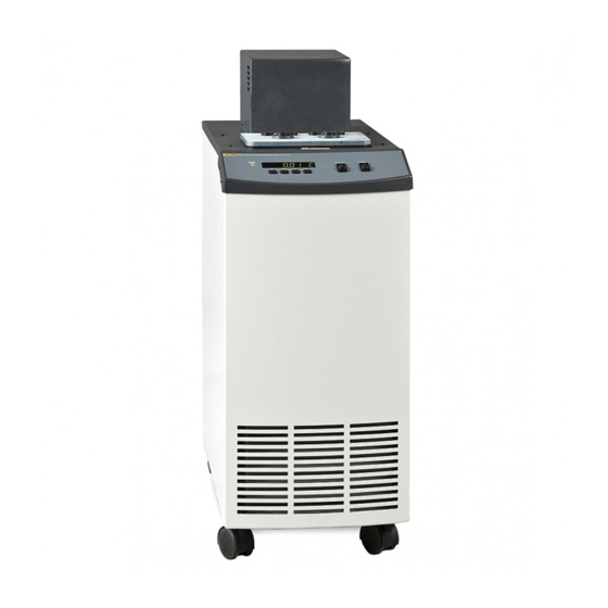
Triple Point of Water Maintenance Bath
7312
User's Guide
Advertisement
Table of Contents
Troubleshooting

Related Manuals for Fluke 7312


Summary of Contents for Fluke 7312
- Page 1 031.526.566 (r.a.) fax 031.507.984 info@calpower.it www.calpower.it 7312 Triple Point of Water Maintenance Bath User’s Guide March 2013 © 2013 Fluke Corporation. All rights reserved. Specifications are subject to change without notice. All product names are trademarks of their respective companies.
- Page 4 Comparison Calibration ..... . . 27 Calibration of Multiple Probes ....27 7 Parts and Controls .
-
Page 5: Table Of Contents
Cutout ....... . 49 Controller Configuration ..... . 50 9.10 Probe Parameters . - Page 6 11.7 Computing D0......68 11.8 Calibrating the Triple Point of Water Cutout ... . 68 12 Charging Instructions .
- Page 7 Figures and Tables Figure 1 Drain Valve Installation—IMPORTANT: Do Not Over Tighten. Follow the installation instructions above....18 Figure 2 Details of the Access Cover and Cell Racks ....23 Figure 3 Fluid Level .
- Page 8 Tables Table 1 International Electrical Symbols ..... 1 Table 2 Table of Various Bath Fluids and Their Properties... . 36 Table 3 Proportional Band - Fluid Table .
-
Page 9: Table 1 International Electrical Symbols
1 Before You Start Symbols Used Before You Start Symbols Used Table 1 lists the International Electrical Symbols. Some or all of these symbols may be used on the instrument or in this manual. Table 1 International Electrical Symbols Symbol Description AC (Alternating Current) AC-DC... - Page 10 7312 TPW Maintenance Bath User’s Guide Symbol Description Canadian Standards Association OVERVOLTAGE (Installation) CATEGORY II, Pollution Degree 2 per IEC1010-1 re- fers to the level of Impulse Withstand Voltage protection provided. Equipment of OVERVOLTAGE CATEGORY II is energy-consuming equipment to be supplied from the fixed installation.
- Page 11 1 Before You Start Safety Information period of 2 hours before it can be assumed to meet all of the safety re- quirements of the IEC 1010-1. If the product is wet or has been in a wet environment, take necessary measures to remove moisture prior to apply- ing power such as storage in a low humidity temperature chamber operat- ing at 50 degree centigrade for 4 hours or more.
- Page 12 7312 TPW Maintenance Bath User’s Guide • The instrument is equipped with a soft cutout (user settable firmware) and a hard cutout (set at the factory). Check the flash point, boiling point, or other fluid characteristic applicable to the circumstances of the unit opera- tion.
- Page 13 Voltage Cut In: ±7.5% (213 - 247 VAC) Authorized Service Centers Please contact one of the following authorized Service Centers to coordinate service on your Hart product: Fluke Corporation, Hart Scientific Division 799 E. Utah Valley Drive American Fork, UT 84003-9775 Phone: +1.801.763.1600...
- Page 14 22 Jianguomenwai Dajie Chao Yang District Beijing 100004, PRC CHINA Phone: +86-10-6-512-3436 Telefax: +86-10-6-512-3437 E-mail: xingye.han@fluke.com.cn Fluke South East Asia Pte Ltd. Fluke ASEAN Regional Office Service Center 60 Alexandra Terrace #03-16 The Comtech (Lobby D) 118502 SINGAPORE Phone: +65 6799-5588 Telefax: +65 6799-5588 E-mail: antng@singa.fluke.com...
- Page 15 1 Before You Start Authorized Service Centers • Serial Number • Voltage • Complete description of the problem...
- Page 16 2 Introduction Introduction The Hart Scientific Model 7312 is a floor standing constant temperature bath. This bath is useful in maintaining up to two triple point of water cells, perform- ing temperature calibration, and other applications requiring stable tempera- tures. An innovative state of the art solid-state temperature controller has been incorporated which maintains the bath temperature with extreme stability.
- Page 17 3 Specifications and Environment Conditions Specifications Specifications and Environment Conditions Specifications Range –5°C to 110°C Stability ±0.001°C at 0°C (alcohol-water mix) ±0.004°C at 30°C (alcohol-water mix) Uniformity ±0.003°C at 0°C (alcohol-water mix) ±0.006°C at 30°C (alcohol-water mix) TPW Duration Six weeks, typical (assumes correctly formed ice mantle) Set-Point Accuracy ±0.05°C at 0°C Set-Point Repeatability...
- Page 19 Unpack the bath carefully and inspect it for any damage that may have oc- curred during shipment. If there is shipping damage, notify the carrier immedi- ately. Verify that all components are present: • 7312 Bath • Access Hole Cover and Components. • Triple Point of Water Support Racks and Adapters.
- Page 20 7312 TPW Maintenance Bath User’s Guide detailed instructions for proper installation of the bath. Be sure to place the bath in a safe, clean and level location. Fill the bath tank with an appropriate liquid. For operation at moderate bath temperatures, clean distilled water works well above 0°C and below 70°C.
- Page 21 4 Quick Start Setting the Temperature Increment display New set-point value C 30.00 Press the “SET” button to accept the new value and to display the vernier value. The bath begins heating or cooling to the new set-point. Store new set-point, access vernier Current vernier value 0.00000 Press the “EXIT”...
- Page 22 Bath Environment The Model 7312 Bath is a precision instrument, which should be located in an appropriate environment. The location should be free of drafts, extreme temper- atures and temperature changes, dirt, etc. The surface where the bath is placed must be level.
-
Page 23: Figure 1 Drain Valve Installation-Important: Do Not Over Tighten
5.3.2 Filling With Fluid The Model 7312 Bath is not provided with a fluid. Various fluids are available from Hart Scientific and other sources. Depending on the desired temperature range, any of the following fluids, as well as others, may be used in the bath: •... - Page 24 5 Installation Power Power With the bath power switch off, plug the bath into an AC mains outlet of the appropriate voltage, frequency, and current capacity. Refer to Section 3.1, Specifications, for power details. Refer to and read the caution at the front of the manual concerning brownout and over voltage protection.
- Page 25 6 Bath Use General Bath Use CAUTION: Read this section entitled BATH USE before placing the bath in service. The information in this section is for general information only. It is not de- signed to be the basis for calibration laboratory procedures. Each laboratory needs to write their specific procedures.
- Page 26 6.2.3 Adjusting the TPW Cell Rack The 7312 bath is provided with two adjustable racks that provide stable loca- tion for the cells. See Figure 2. Remove the racks by reaching in and withdraw- ing them. The stainless steel baffles on the left and right sides of the tank act as guides or tracks to locate and retain each rack.
-
Page 27: Figure 2 Details Of The Access Cover And Cell Racks
6 Bath Use Triple Point of Water Cell Maintenance Rubber Shock Guides Thermometer Precooling Holes Access Cover Removable Guide Tubes Adapter Guide Location Top Plate Adjusting Set Screws Support Rods TPW Cells Baffle Rubber Grommet Bottom Plate Guide Location Figure 2 Details of the Access Cover and Cell Racks... - Page 28 7312 TPW Maintenance Bath User’s Guide Adjusting the fluid level so that the top bell is exposed permits added heat input to the cell causing the top of the ice mantle to melt. Careful adjustment can ad- equately maintain the cell while reducing the ice bridging at the top of the cell.
-
Page 29: Figure 3 Fluid Level
6 Bath Use Triple Point of Water Cell Maintenance Fluid Level in Bath Figure 3 Fluid Level... -
Page 30: Figure 4 Location Of Handles For Nbs Design Cells
7312 TPW Maintenance Bath User’s Guide Figure 4 Location of Handles for NBS Design Cells • Check for ice bridging every 1 to 3 days as required. Ice bridging is ice forming at the top surface of the water in the cell that bridges from the reentrant tube to the outer glass wall. - Page 31 6 Bath Use Comparison Calibration Comparison Calibration Comparison calibration involves testing a probe (unit under test, UUT) against a reference probe. After inserting the probes to be calibrated into the bath, al- low sufficient time for the probes to settle and the temperature of the bath to stabilize.
-
Page 32: Figure 5 Front Controller Panel
7 Parts and Controls Front Panel Parts and Controls Front Panel The following controls and indicators are present on the controller front panel (see Figure 5 below): (1) the digital LED display, (2) the control buttons, (3) the bath on/off power switch, (4) the control indicator light, and (5) the cooling on/off switch. - Page 33 7312 TPW Maintenance Bath User’s Guide 5. The cooling on/off switch turns on the refrigeration for control below 50°C and rapid cool down. Bath Tank and Lid The bath tank and lid assembly includes: the tank, the control probe, the stir- ring motor, the access hole, and the access hole cover.
- Page 34 Heat Transfer Fluid General Operation Heat Transfer Fluid Many fluids work with 7312 bath. Choosing a fluid requires consideration of many important characteristics of the fluid. Among these are temperature range, viscosity, specific heat, thermal conductivity, thermal expansion, electri- cal resistivity, fluid lifetime, safety, and cost.
- Page 35 7312 TPW Maintenance Bath User’s Guide 8.1.4 Thermal Conductivity Thermal conductivity measures how easily heat flows through the fluid. Ther- mal conductivity of the fluid affects the control stability, temperature unifor- mity, and temperature settling time. Fluids with higher conductivity distribute heat more quickly and evenly improving bath performance.
- Page 36 8 General Operation Heat Transfer Fluid Ds=9.2/[0.00077 (300-25) + 1] = 7.59 inches 8.1.6 Electrical Resistivity Electrical resistivity describes how well the fluid insulates against the flow of electric current. In some applications, such as measuring the resistance of bare temperature sensors, it may be important that little or no electrical leakage oc- cur through the fluid.
- Page 37 7312 TPW Maintenance Bath User’s Guide 8.1.9 Cost Cost of bath fluids may vary greatly, from cents per gallon for water to hun- dreds of dollars per gallon for synthetic oils. Cost may be an important consid- eration when choosing a fluid.
- Page 38 8 General Operation Heat Transfer Fluid characteristics, which are somewhat poorer than water. The viscosity changes significantly with temperature and also causes thermal expansion to occur. These oils have very high electrical resistivity. Silicone oils are fairly safe and non-toxic. Silicone oils are fairly expensive. 8.1.11 Fluid Characteristics Charts Table 2 and Figure 6 on pages 36 and 37 have been created to provide help in...
-
Page 39: Table 2 Table Of Various Bath Fluids And Their Properties
7312 TPW Maintenance Bath User’s Guide Table 2 Table of Various Bath Fluids and Their Properties Lower Upper Thermal Thermal Fluid Temperature Temperature Flash Viscosity Specific Specific Heat Conductivity Expansion Resistivity (# = Hart Part No.) Limit* Limit* Point (centistokes) Gravity (cal/g/°C) -
Page 40: Figure 6 Chart Of Various Bath Fluids And Their Properties
8 General Operation Stirring –100°C 0°C 100°C 200°C 300°C 400°C 500°C 600°C Silicone Oil FL 302°C 10 CS 5017 Silicone Oil FL 280°C 10 CS 5014 Silicone Oil FL 232°C 10 CS 5013 Silicone Oil FL 211°C 5012 10 CS Silicone Oil FL 133°C 10 CS... - Page 41 7312 TPW Maintenance Bath User’s Guide Power Power to the bath is provided by an AC mains supply. Refer to Section 3.1, Specifications, for power details. Refer to and read the CAUTION at the front of the manual concerning brownout and over voltage protection. Check the back panel label for the correct voltage and frequency prior to energizing the unit.
- Page 42 8 General Operation Refrigeration The controller allows the operator to set the bath temperature with high resolu- tion, set the cutout, adjust the proportional band, monitor the heater output power, and program the controller configuration and calibration parameters. The controller may be operated in temperature units of degrees Celsius or Fahr- enheit.
- Page 43 9 Controller Operation Bath Temperature Controller Operation This chapter discusses in detail how to operate the bath temperature controller using the front control panel. Using the front panel key switches and LED dis- play the user may monitor the bath temperature, set the temperature set-point in degrees C or F, monitor the heater output power, adjust the controller propor- tional band, set the cutout set-point, and program the probe calibration parame- ters, operating parameters, serial and IEEE-488 interface configuration, and...
-
Page 44: Figure 7 Controller Operation Flowchart
7312 TPW Maintenance Bath User’s Guide Display Secondary Functions Temperature EXIT Display Power EXIT EXIT Reset Cutout Cutout Active Set Proportional Band EXIT Select Setpoint EXIT EXIT Set Cutout Temp. Adjust Setpoint EXIT Adjust Vernier EXIT EXIT Set Scale °C/°F... - Page 45 9 Controller Operation Temperature Set-point Press the “SET” button once more to reset the cutout. Reset cutout This action also switches the display to the set temperature function. To return to displaying the temperature, press the “EXIT” button. If the cutout is still in the over-temperature fault condition, the display continues to flash “cutout”.
- Page 46 7312 TPW Maintenance Bath User’s Guide 9.3.2 Set-point Value The set-point value may be adjusted after selecting the set-point memory and pressing the “SET” button. The set-point value is displayed with the units, C or F, at the left. C 40.00 Set-point value in °C...
- Page 47 9 Controller Operation Temperature Scale Units Next press the “EXIT” button to return to the temperature display or the “SET” button to access the temperature scale units selection. Access scale units Temperature Scale Units The temperature scale units of the controller may be set by the user to degrees Celsius (°C) or Fahrenheit (°F).
- Page 48 7312 TPW Maintenance Bath User’s Guide Secondary Menu Functions, which are used less often, are accessed within the secondary menu. The secondary menu is accessed by pressing the “SET” and “EXIT” buttons si- multaneously and then releasing. The first function in the secondary menu is the heater power display.
-
Page 49: Figure 8 Bath Temperature Fluctuation At Various Proportional Band Settings
9 Controller Operation Proportional Band If the proportional band is too narrow the bath temperature may swing back and forth because the controller overreacts to temperature variations. For best control stability the proportional band must be set for the optimum width. Proportional Band too Narrow Proportional Band too Wide Optimum Proportional Band... -
Page 50: Proportional Band - Fluid Table
7312 TPW Maintenance Bath User’s Guide tional band settings for optimum performance with a variety of fluids at se- lected temperatures. Table 3 Proportional Band - Fluid Table Fluid Temperature Proportional Band Stability Water 30°C 0.31°C ±0.003°C Water 60°C 0.31°C ±0.003°C... -
Page 51: Cutout
9 Controller Operation Cutout Cutout As a protection against software or hardware fault, shorted heater triac, or user error, the bath is equipped with an adjustable heater cutout device that shuts off power to the heater if the bath temperature exceeds a set value. This protects the heater and bath materials from excessive temperatures and, most impor- tantly, protects the bath fluids from being heated beyond the safe operating temperature preventing hazardous vaporization, breakdown, or ignition of the... -
Page 52: Controller Configuration
7312 TPW Maintenance Bath User’s Guide Accept cutout set-point The next function is the configuration menu. Press the “EXIT” button to re- sume displaying the bath temperature. Controller Configuration The controller has a number of configuration and operating options and calibra- tion parameters, which are programmable via the front panel. - Page 53 9 Controller Operation Operating Parameters Operating parameters menu Press the “UP” button to enter the menu. The operating parameters menu con- tains the cutout reset mode parameter. 9.11.1 Cutout Reset Mode The cutout reset mode determines whether the cutout resets automatically when the bath temperature drops to a safe value or must be manually reset by the operator.
-
Page 54: Baud Rate
7312 TPW Maintenance Bath User’s Guide tP CO Triple point of water cutout parameter Press the “SET” button to access the activation selection. Press the “UP” or “DOWN” button to turn the cutout on or off and then press the “SET” button. -
Page 55: Sample Period
9 Controller Operation Serial Interface Parameters Press the “SET” button to set the BAUD rate to the new value or the “EXIT” button to abort the operation and skip to the next parameter in the menu. 9.12.2 Sample Period The sample period is the next parameter in the serial interface parameter menu. The sample period is the time period in seconds between temperature measure- ments transmitted from the serial interface. -
Page 56: Transmission Termination
7312 TPW Maintenance Bath User’s Guide ASCII 10) after transmission of any carriage-return. The linefeed parameter is indicated by, Serial linefeed parameter Press the “SET” button to access the linefeed parameter. LF=On Current linefeed setting The mode may be changed using the “UP” or “DOWN” button and then press- ing the “SET”... -
Page 57: Calibration Parameters
9.14.1 Parameter CTO sets the calibration of the over-temperature cutout. This param- eter is not adjustable by software but is adjusted with an internal potentiometer. For the 7312 bath this parameter should read 160. 9.14.2 H and L These parameters set the upper and lower set-point limits of the bath. DO NOT... - Page 58 7312 TPW Maintenance Bath User’s Guide present danger of the bath exceeding its temperature range causing damage or fire.
-
Page 59: Serial Communications
Serial Communications Digital Communication Interface The 7312 bath is capable of communicating with and being controlled by other equipment through the digital interface. Two types of digital interface are avail- able—the RS-232 serial interface, which is standard, and the IEEE-488 GPIB interface which is optional. -
Page 60: Setup
7312 TPW Maintenance Bath User’s Guide and suggested cable wiring. To eliminate noise, the serial cable should be shielded with low resistance between the connector (DB-9) and the shield. Figure 9 Serial Communications Cable Wiring 10.1.2 Setup Before operation, the serial interface of the bath must first be set up by pro- gramming the BAUD rate and other configuration parameters. -
Page 61: Sample Period
10 Digital Communication Interface IEEE-488 Communication (optional) BAUD rate of the bath may be programmed to 300, 600, 1200, or 2400 BAUD. The BAUD rate is pre-programmed to 2400 BAUD. Use “UP” or “DOWN” to change the BAUD rate value. Press the “SET” button to set the BAUD to the new value or the “EXIT”... -
Page 62: Setup
7312 TPW Maintenance Bath User’s Guide 10.2.1 Setup To use the IEEE-488 interface connect an IEEE-488 standard cable to the back of the bath, set the device address, and set the transmission termination character. To enter the IEEE-488 parameter programming menu, press the “EXIT” and the “SET”... -
Page 63: Interface Command Summary
10 Digital Communication Interface Interface Commands Table 4 Interface Command Summary. Command Command Returned Acceptable Command Description Format Example Returned Example Values Display Temperature Read current set-point s[etpoint] set: 9999.99 {C or F} set: 100.000 C Set current set-point to n s[etpoint]=n s=100 Instrument... -
Page 64: Interface Command Summary Continued
7312 TPW Maintenance Bath User’s Guide Interface Command Summary continued Command Command Returned Acceptable Command Description Format Example Returned Example Values Set cut-out to be reset cm[ode]=a[uto] cm=a automatically Read water triple point tpco tpco tpco:{ON or OFF} tpco=ON Set water triple point... - Page 65 10 Digital Communication Interface Power Control Functions data, denoted by “n”, may be entered in decimal or exponential notation. Char- acters are shown in lower case although upper case may be used. Spaces may be added within command strings and are simply ignored. Backspace (BS, ASCII 8) may be used to erase the previous character.
-
Page 66: Calibration Procedure
11 Calibration Procedure Calibration Points—2 Point Calibration Calibration Procedure In some instances the user may want to calibrate the bath to improve the tem- perature set-point accuracy. Calibration is done by adjusting the controller probe calibration constants DO and DG so that the temperature of the bath as measured with a standard thermometer agrees more closely with the bath set-point. -
Page 67: Calibration Example
7312 TPW Maintenance Bath User’s Guide The user should keep a record of these values in case they may need to be re- stored in the future. The new values DO’ and DG’ are computed by entering the old values for DO and DG, the calibration temperature set-points, t... -
Page 68: Figure 10 Sample Calibration Computations
11 Calibration Procedure Measuring the Set-point Error D0 = -25.229 DG = 0.0028530 = 25.00°C measured t = 24.869°C = 75.00°C measured t = 74.901°C Compute errors, = 24.869 – 25.00°C = –0.131°C = 74.901 – 75.00°C = –0.099°C Compute D0, −... -
Page 69: Computing D0
7312 TPW Maintenance Bath User’s Guide Example: Actual temperature = +0.132°C Set point temperature = +0.008°C error = +0.008– (+0.132) = -0.124 (including sign) 11.7 Computing D0 Before computing the new values for D0, the current value must be known. The value may be found by either accessing the probe calibration menu from the controller panel or by inquiring through the digital interface. - Page 70 11 Calibration Procedure Calibrating the Triple Point of Water Cutout The cutout is calibrated by adjusting a potentiometer inside the unit while the bath is at the triple point maintenance temperature. The bath temperature should be known to within ±0.05°C. A DVM capable of measuring accurately to 10mV is required.
-
Page 71: Charging Instructions
12 Charging Instructions Leak Testing Charging Instructions The 7312 uses R-134a with a polyolester oil. Care must be taken to avoid con- tamination from other types of refrigerants and oils. 12.1 Leak Testing Leak testing should be done with equipment designed for use with R-134a. -
Page 72: Maintenance
13 Maintenance Maintenance • A battery is used to maintain operating parameters in the unit. All operat- ing parameters, including calibration parameters should be checked on a regular basis to insure accuracy and proper operation of the instrument. See the troubleshooting section for the procedure on checking the status of the battery. - Page 73 7312 TPW Maintenance Bath User’s Guide • If the mains supply cord becomes damaged, replace it with a cord with the appropriate gauge wire for the current of the bath. If there are any questions, call an Authorized Service Center for more information.
-
Page 74: Troubleshooting
14 Troubleshooting Troubleshooting Troubleshooting This section contains information on troubleshooting, CE Comments, and a wiring diagram. This information pertains to a number of bath models and cer- tain specifics may not pertain to your model. 14.1 Troubleshooting In the event that the instrument appears to function abnormally, this section may help to find and solve the problem. - Page 75 7312 TPW Maintenance Bath User’s Guide Problem Causes and Solutions The heater indicator LED If the display does not show “cutout” and shows the correct bath temperature, stays red but the temper- consider the following possibilities: ature does not increase No heating.
-
Page 76: Troubleshooting
14 Troubleshooting Troubleshooting Problem Causes and Solutions The controller controls or If the controller appears to operate normally except that the bath’s temperature attempts to control at an does not agree with the temperature measured by the user’s reference ther- inaccurate temperature mometer to within the specified accuracy, consider the following: Erroneous parameters. -
Page 77: Comments
7312 TPW Maintenance Bath User’s Guide Problem Causes and Solutions The controller does not Note: Before performing the memory check,you need to record the controller maintain controller pa- calibration parameters (found in the CAL menu of the instrument) and any...
Need help?
Do you have a question about the 7312 and is the answer not in the manual?
Questions and answers