
Related Manuals for Raven SBGuidance Side-Shift


Summary of Contents for Raven SBGuidance Side-Shift
- Page 1 INSTALLATION MANUAL SBGuidance Side-Shift Side-Shift and Drawbar steering (Original Instructions)
- Page 2 SBGuidance Side-Shift I Version 1.1 I CAN Pag 2/30 I SBG-Side-Shift-IM-EN-V1.1...
-
Page 3: Table Of Contents
SBGuidance Side-Shift I Version 1.1 I CAN Table of contents Preface ..........................5 Disclaimer ..........................6 Instructions for installing SBGuidance Side-Shift ............7 1.1. Overview of basic components for the Side-Shift/Drawbar steering ....... 9 1.2. Overview Side-Shift adapter frame and cylinders (optional) ......... 10 1.3. - Page 4 SBGuidance Side-Shift I Version 1.1 I CAN 3.2.2. Pulse steering ....................24 3.3. Calibrating angle sensor ..................25 3.4. Configuration PID controllers ................26 3.5. Configurator set-up ....................27 3.6. Calibrating DynamIQ .................... 27 3.7. Checking centre adjustments................28 Annex ......................... 29 4.1.
-
Page 5: Preface
Preface This configuration manual is intended for persons responsible for installating an SBGuidance Side-Shift set. The manual contains important instructions that should be complied with when commissioning, operating and servicing the SBGuidance system. This manual has been compiled with the utmost care. SBG Precision Farming assumes no responsibility for any errors or omissions in this document. -
Page 6: Disclaimer
SBGuidance Side-Shift I Version 1.1 I CAN Disclaimer Warning!: Always switch off the tractor before installing or repairing hydraulic and electrical components of the SBGuidance system. Warning! The system contains moving parts! Make sure the immediate environment is clear of people before operating the system... -
Page 7: Instructions For Installing Sbguidance Side-Shift
SBGuidance Side-Shift I Version 1.1 I CAN Warning!: Only allow authorized/qualified persons to operate the system. Authorized/qualified persons include: Persons who have read and understood the operating manual and who are both physically and mentally fit to operate the system. - Page 8 SBGuidance Side-Shift I Version 1.1 I CAN Pag 8/30 I SBG-Side-Shift-IM-EN-V1.1...
-
Page 9: Overview Of Basic Components For The Side-Shift/Drawbar Steering
SBGuidance Side-Shift I Version 1.1 I CAN 1.1. Overview of basic components for the Side-Shift/Drawbar steering Sign Part-number Description Harness Implement 4,0 m – TWIN SBG13713-01 STU – Side-Shift Steering SBG10919-07 SBG12705-05 STU bracket SBG10911-01 DynamIQ Implement SBG12700 DynamIQ universal bracket... -
Page 10: Overview Side-Shift Adapter Frame And Cylinders (Optional)
SBGuidance Side-Shift I Version 1.1 I CAN 1.2. Overview Side-Shift adapter frame and cylinders (optional) Sign Part-number Description SBG12400 Side-Shift frame (excl. cylinder) SBG10650 Side-Shift cylinder Cat 2 2000 kg SBG10651-01 Side-Shift cylinder Cat 3 4500 kg SBG10652 Side-Shift cylinder Cat 3 8000 kg... -
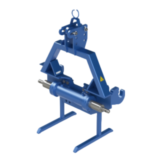
Page 11: Assembled Side-Shift Frame
SBGuidance Side-Shift I Version 1.1 I CAN 1.3. Assembled Side-Shift frame Hydraulisch Steering Controller manifold (STU) Angle Senor Side-Shift cylinder When using the Side-Shift adapter frame it’s advised to place both GPS-antenna and DynamIQ on the attached implement. Keep the distance to the cylinder as short as possible! In case of frequent implement changes the DynamIQ could be placed on the adapter frame. -
Page 12: Installation Basic Components
SBGuidance Side-Shift I Version 1.1 I CAN 2. Installation basic components It’s advised to install the Side-Shift or drawbar steering in the order as listed below: 1. Installing the Side-Shift cylinder (if necessary). 2. Checking the hydraulic manifold. 3. Mounting of the manifold and connecting the hydraulic hoses. -
Page 13: Checking The Hydraulic Manifold
SBGuidance Side-Shift I Version 1.1 I CAN 2.2. Checking the hydraulic manifold The hydraulic implement manifold is suited for use in both Load-Sense (L.S.) and Open Center (O.C.) hydraulic systems. Depending on the type of installation a different type of selector plug must be installed in the manifold (Table 1, Figure 2). -
Page 14: Mounting Of The Steering Controller
SBGuidance Side-Shift I Version 1.1 I CAN Load Sense Connect the pressure line to P, the return line to T and the sensor line to LS on the manifold. Use the Load Sense (L.S.) connections of the tractor. Open Center Connect the pressure line to P and the return line to T on the manifold. -
Page 15: Mounting Of The Angle Sensor In The Bracket
SBGuidance Side-Shift I Version 1.1 I CAN 2.5.1. Mounting of the angle sensor in the bracket Use the following description to mount the angle sensor in the bracket (Figure 6): 1. The sensor consists of two parts, both need to be mounted with M5 bolts. The smallest piece (little disc) needs to be mounted to the “arm”-bracket and the... -
Page 16: Drawbar Steering
SBGuidance Side-Shift I Version 1.1 I CAN In a Side-Shift steering kit an angle sensor is delivered in an angle sensor bracket by standard. Keep in mind that the max angle of the sensor is around 90°. A good reference position is to... -
Page 17: Mounting Of The Gps-Antenna
SBGuidance Side-Shift I Version 1.1 I CAN 2.6. Mounting of the GPS-Antenna The most suited antenna position depends on the implement that’s being used. When using mounted implements with Side- Shift steering it’s advised to mount the antenna as close to the cylinder as possible (Figure 11). -
Page 18: Placing And Connecting Cabling
SBGuidance Side-Shift I Version 1.1 I CAN 2.8. Placing and connecting cabling An Implement-ready wiring harness is required on the tractor for connecting the Side-Shift or drawbar steering. The IBBC connector ensures that connection (Figure 13). Section 2.9 shows a schematic view of the lead connecting circuit. -
Page 19: Can Implement Harness (Schematics)
SBGuidance Side-Shift I Version 1.1 I CAN 2.9. CAN implement harness (schematics) Figure 15 CAN implement harness Pag 19/30 I SBG-Side-Shift-IM-EN-V1.0... -
Page 20: Configuration And Calibration
SBGuidance Side-Shift I Version 1.1 I CAN 3. Configuration and calibration The following software and firmware versions are required for the set-up, calibration and use of the CAN Side-Shift controller: CAN-Tool 1.28 or more recent version. Side-Shift steering firmware STU_Side- Shift_2.0.30 or more recent version... -
Page 21: Determine Control Speeds
SBGuidance Side-Shift I Version 1.1 I CAN open the set-up screen for the CAN Side-Shift steering (Figure 18). The steering controller is recognized if the status is on Running, if an SW Version is displayed and the correct type of STU is detected. -
Page 22: Proportional Steering
SBGuidance Side-Shift I Version 1.1 I CAN Allow the oil from the tractor to warm up before starting the determination of the control rates. The steering can be checked by pressing one of the Test buttons on the tab page... - Page 23 SBGuidance Side-Shift I Version 1.1 I CAN Determine the minimum control values in the central range (i.e. from the straight forward position). Important: When minimum control values are applied, the control response to the left or to the right should be just as quick.
-
Page 24: Pulse Steering
SBGuidance Side-Shift I Version 1.1 I CAN 3.2.2. Pulse steering 1. In tab named “PID Steer” (Figure 22) select at “Controller Type”: “On/Off” 2. Go to tab “Steering” (Figure 23). Check if steer left makes the cylinder steer left, if not mark the “L/R Inv”... -
Page 25: Calibrating Angle Sensor
SBGuidance Side-Shift I Version 1.1 I CAN 3.3. Calibrating angle sensor The angle sensor serves to provide feedback relating to the actual position of the Side-Shift cylinder or drawbar. Side-Shift steering uses the angle sensor for displaying the actual cylinder position in the software and making the “Auto-Centre”... -
Page 26: Configuration Pid Controllers
SBGuidance Side-Shift I Version 1.1 I CAN 3.4. Configuration PID controllers When using a proportional hydraulic valve the aggressiveness of the steering can be tuned in the ‘PID Steer” tab. Use the default settings for the PID controllers as shown in Figure 26. The response of the controllers can be adjusted by changing the dealer gain percentages. -
Page 27: Configurator Set-Up
SBGuidance Side-Shift I Version 1.1 I CAN 3.5. Configurator set-up Add an machine-profile to the loader screen and name it appropriately. Refer to the SBGuidance Auto CAN set- up and configuration manual for further information on how to install SBGuidance and make machine profiles. -
Page 28: Checking Centre Adjustments
SBGuidance Side-Shift I Version 1.1 I CAN 3.7. Checking centre adjustments The centre position of the Side-Shift system is important in order to ensure the correct successive follow-up of work operations. If the DynamIQ is calibrated and the GPS antenna is... -
Page 29: Annex
SBGuidance Side-Shift I Version 1.1 I CAN 4. Annex 4.1. Pin-out STU connectors Table 2 STU B-connector (Black) Pin Description VCC / PWM ACT Ground ACT Switched ECU Power Input 3 (no function) 5V sensor power (optional) Angle sensor signal... -
Page 30: Pin-Out Angle Sensor
SBGuidance Side-Shift I Version 1.1 I CAN 4.2. Pin-out Angle sensor Table 4 Deutsch DTM06-4S angle sensor 12V Pin Description Wire colour 5V sensor power ECU ground Blue Sensor signal Black 12V sensor power Brown Pag 30/30 I SBG-Side-Shift-IM-EN-V1.1...
Need help?
Do you have a question about the SBGuidance Side-Shift and is the answer not in the manual?
Questions and answers