
Related Manuals for SIGRIST ColorPlus 2


Summary of Contents for SIGRIST ColorPlus 2
- Page 1 Document number: 13045E Version: 3 Valid from: S/N 431225 / SW V129 INSTRUCTION MANUAL ColorPlus 2 Absorption Measuring Instrument...
- Page 2 Copyright© SIGRIST-PHOTOMETER AG, subject to technical changes without notice 11/2019 SIGRIST-PHOTOMETER AG Tel. +41 41 624 54 54 Hofurlistrasse 1 +41 41 624 54 55 CH-6373 Ennetbürgen info@photometer.com Switzerland www.photometer.com...
-
Page 3: Table Of Contents
......15 Designation of the ColorPlus 2................ 16 Scope of supply and accessories..............17 Technical data for the ColorPlus 2..............22 General safety points ....................26 Dangers when properly used ................26 Storing the calibration aids ................27 Residual risk .................... - Page 4 Instruction Manual ColorPlus 2 Contents Operation basics ..................... 54 Control elements in measuring mode ............. 55 Menu button ....................55 Valu button ....................55 Info button ..................... 56 Diag button ....................58 Functions of the log screen (Log button) ............59 Displays in measuring mode ................
-
Page 5: General User Information
Purpose of the Instruction Manual This Instruction Manual provides the user with helpful information about the entire life cycle of the ColorPlus 2 and its peripheral devices. Before commissioning the instrument, you should be completely familiar with the Instruction Manual. -
Page 6: Order Document
The most recent version of this document can be downloaded at www.photometer.com (first time registration required). It can also be ordered from a SIGRIST representative in your country ( Instruction Manual “Customer service information”). Proper use The photometer and its peripherals are designed for measuring the absorption of liquids and gases. -
Page 7: Dangers When Not Used Properly
The instrument is not properly mounted, set up or transported. The instrument is not installed and operated in accordance with the Instruction Manual. The instrument has been operated with accessory parts which SIGRIST-PHOTOMETER AG has not expressly recommended. Improper changes to the instrument have been performed. -
Page 8: Meaning Of The Safety Symbols
Instruction Manual ColorPlus 2 General user information 1.13 Meaning of the safety symbols All danger symbols used in this document are explained below: Danger due to electrical shock that may result in serious bodily injury or death. Non-observance of this notice may lead to electrical shocks and death. -
Page 9: Meaning Of The Pictograms
1.14 Meaning of the pictograms All pictograms used in this document are explained below: Additional information about the current topic. Practical procedures when working with the ColorPlus 2. Manipulations on the touchscreen. The screenshot is an example and may differ from current device. -
Page 10: Instrument Overview
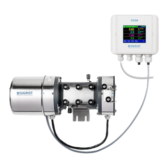
Instruction Manual ColorPlus 2 Instrument overview Instrument overview Overview of a water measuring point Figure 1: Overview of a water measuring point with PVC measuring cell SICON control unit Transmitter PVC bypass measuring cell Receiver with external checking unit 100/50 mm optical path length ... -
Page 11: Overview Of An Ozone Measuring Point
Instrument overview Instruction Manual ColorPlus 2 Overview of an ozone measuring point Figure 2: Overview of an ozone measuring point with Stainless steel measuring cell SICON control unit Receiver External checking unit Stainless steel measuring cell ... -
Page 12: Overview Of A Chlorine Measuring Point
Instruction Manual ColorPlus 2 Instrument overview Overview of a chlorine measuring point Figure 3: Overview of a chlorine measuring point with PVDF measuring cell SICON control unit Transmitter PVDF measuring cell Measuring cell outlet ... -
Page 13: Overview Of A Beverage Measuring Point
Instrument overview Instruction Manual ColorPlus 2 Overview of a beverage measuring point ® The following overview shows the installation of the ColorPlus 2 in a VARINLINE housing. Installation in a customer-specific measuring cell is made in the same way. ®... -
Page 14: Overview Of A Measuring Point With Sliding Measuring Cell
Instruction Manual ColorPlus 2 Instrument overview Overview of a measuring point with sliding measuring cell The following overview shows a measuring point with sliding measuring cell. The photome- ter can be moved from the measurement position for recalibration without having to inter- rupt the sample flow. -
Page 15: Overview Of A Measuring Point For The
Pre-treatment: Post-treatment: a: ColorPlus 2 with PVC a: ColorPlus 2 with PVC measuring cell measuring cell b: Compressed air control valve b: Compressed air control valve c: Jet pump c: Jet pump d: Cleaning agent valve... -
Page 16: Designation Of The Colorplus 2
Instruction Manual ColorPlus 2 Instrument overview Designation of the ColorPlus 2 The SICON control unit and ColorPlus 2 photometer are each fitted with a rating plate: Figure 7: Rating plates on the instruments Manufacturer Country of origin ... -
Page 17: Scope Of Supply And Accessories
Instrument overview Instruction Manual ColorPlus 2 Scope of supply and accessories 2.8.1 Standard scope of supply for the ColorPlus 2 PCS. ART. NO. NAME VIEW VARIANT See the ColorPlus 2 ColorPlus 2 for wa- website ter, ozone and bev- erages, or as cus-... - Page 18 Instruction Manual ColorPlus 2 Instrument overview PCS. ART. NO. NAME VIEW VARIANT On request PVDF measuring * 32 mm cell (for hazardous samples) 117853 (VIS) Checking unit With 1% filter 117854 (UV) Documentation: PCS. ART. NO. NAME VIEW VARIANT 20012...
- Page 19 Instrument overview Instruction Manual ColorPlus 2 PCS. ART. NO. NAME VIEW VARIANT 119795 4-way current in- For SICON (M) only On request Calibration measu- For sliding measuring ring cell cell See the Additional check- website ing units with filter values of 80%,...
- Page 20 Instruction Manual ColorPlus 2 Instrument overview 2.8.3 Standard scope of supply for the ColorPlus 2, 4 clarification stage PCS. ART. NO. NAME VIEW VARIANT 121800 clarification stage * With hex key for 32 with two ColorPlus mm window screw 2, Powerbox and...
- Page 21 Instrument overview Instruction Manual ColorPlus 2 2.8.4 Optional accessories for the ColorPlus 2, 4 clarification stage PCS. ART. NO. NAME VIEW VARIANT See the Additional check- website ing units with filter values of 80%, 50%, 20%, 10 % and 3 %...
-
Page 22: Technical Data For The Colorplus 2
Instruction Manual ColorPlus 2 Instrument overview Technical data for the ColorPlus 2 2.9.1 Technical data ColorPlus 2 Absorption measu- Values rement Measuring principle Absorption Measuring span 0 .. 0.1 E to 0 .. 3 E Measuring ranges 8, freely configurable Wavelength 1 .. - Page 23 Instrument overview Instruction Manual ColorPlus 2 Photometer Values Dimensions See detailed dimension drawing Weight Depending on version approx. 4 – 4.3 kg (flow cell not included) Protection class IP 65 Ambient temperature -20 .. 50 °C at higher medium temperatures, cooling is possibly...
- Page 24 Instruction Manual ColorPlus 2 Instrument overview SICON control unit Values Service voltage and 9 .. 30 VDC with VIS version power consumption 24 VDC with UV version 5 W only SICON control unit Display ¼ VGA with touchscreen Resolution: 320 x 240 pixels with 3.5“...
- Page 25 Instrument overview Instruction Manual ColorPlus 2 2.9.2 Technical data for the ColorPlus 2, 4 clarification stage Data Values Measuring principle Absorption Measuring scope 0 .. 3 E Measuring ranges 8, freely configurable Wavelength 254 nm Resolution 0.001 E Service voltage 100 ..
-
Page 26: General Safety Points
Check that there are no leaks on a regular basis. CAUTION! Penetration of moisture as well as condensation on the electrical components dur- ing operation. If moisture enters the instrument, the ColorPlus 2 can be damaged. The USB interface cover must always be attached during operation. CAUTION! ... -
Page 27: Storing The Calibration Aids
Penetration of moisture as well as condensation on the electrical components dur- ing servicing duty. If moisture enters the instrument, the ColorPlus 2 can be damaged. Work inside the instrument may be performed only in a dry room and at room tempera- CAUTION! ture. -
Page 28: Residual Risk
Instruction Manual ColorPlus 2 General safety points Residual risk According to the risk assessment of the applied safety directive DIN EN 61010-1, there remains the risk of the displayed measuring values being incorrect. This risk can be reduced with the following measures: ... -
Page 29: Preventing Undesirable Online Access Attempts
Instruction Manual ColorPlus 2 Preventing undesirable online access attempts SIGRIST instruments are equipped with an integrated web user interface and Mod- bus TCP interface, thus offering state-of-the-art administration and control possibil- ities. However, if these are connected directly to the Internet, then any Internet us- er can in principle access your instrument and change the configuration. -
Page 30: Mounting
Instruction Manual ColorPlus 2 Mounting Mounting Mounting the photometer for a water measuring point The photometer must be installed horizontally. The water outlet must be positioned at the top so that the measuring cell can be well ventilated. WORKSTEP ADDITIONAL INFO / IMAGES Install the photometer onto a wall using two screws on the fastening plate (A). -
Page 31: Mounting The Photometer On The Inline Housing
Mounting Instruction Manual ColorPlus 2 Mounting the photometer on the inline housing 4.2.1 Mounting position of the photometer in the inline housing ® Using a standardized inline housing (VARINLINE or compatible models), the photometer can be installed in both horizontal and vertical product lines. - Page 32 Lock ring Flood protection The ColorPlus 2 is delivered with an OPL bit (Figure 8, pos. 6) on both sides for installation in an inline housing. The OPL bits with measuring cell window (Figure 8, pos. 3), the corre- sponding flood protection (Figure 8, pos. 8) and ring adapter (Figure 8, pos. 2) are already installed according to customer requirements at the factory.
-
Page 33: Mounting The Photometer With Sliding Measuring Cell
Mounting Instruction Manual ColorPlus 2 Mounting the photometer with sliding measuring cell The following points must be observed for mounting a photometer with sliding measuring cell: The photometer with sliding measuring cell may only be installed in vertical sample lines. - Page 34 Instruction Manual ColorPlus 2 Mounting 4.4.3 Connecting the sample feed and compressed air Danger due to acidic or toxic liquids. Non-observance of this warning can lead to permanent damage to the eyes and skin. Ad- here to the following instructions: Wear protective gogg- Wear gloves and safety clothing.
- Page 35 Mounting Instruction Manual ColorPlus 2 WORKSTEP ADDITIONAL INFO / IMAGES Mount the sample drain (arrows) and fasten in place. Carry out this procedure for pre- treatment and post-treatment (Section 2.6). Injuries to the eyes and skin due to the uncontrolled release of cleaning agent into the surrounding area.
-
Page 36: Connecting The Cooling Water (Optional)
Instruction Manual ColorPlus 2 Mounting Connecting the cooling water (optional) The photometer must be equipped with a cooling system. WORKSTEP ADDITIONAL INFO / IMAGES Connect the inlet (A) and outlet (B) to a water circuit. Conventional silicone hoses for nipple diame- ters of 9.5 mm can be used here. -
Page 37: Mounting The Sicon (M)
Mounting Instruction Manual ColorPlus 2 Mounting the SICON (M) WORKSTEP ADDITIONAL INFO / IMAGES Open the shutters. Fasten the control unit to the wall using four screws (circles). 13045E/3... -
Page 38: Electrical Installation
Instruction Manual ColorPlus 2 Electrical installation Electrical installation Safety pointers for the electrical connection Connecting the service voltage. Improper connection of the service voltage can be potentially fatal. The system may also be damaged. Local regulations for electrical connection must be observed at all times. -
Page 39: Opening The Cover On The Sicon (M)
Electrical installation Instruction Manual ColorPlus 2 Opening the cover on the SICON (M) WORKSTEP ADDITIONAL INFO / IMAGES Open the shutters. Loosen the fastening screws on the cover. Open the cover. Fasten the cover with the cover clamp. To do this, remove the cover clamp from the park po- sition (X) and fasten the cover in position (Y). -
Page 40: Overview Of The Opened Sicon (M) Control Unit
Instruction Manual ColorPlus 2 Electrical installation Overview of the opened SICON (M) control unit Figure 9: Overview of SICON (M) Park position for cover clamp microSD card (card for log data) USB connection Ethernet connection ... -
Page 41: Connecting The Sicon (M)
Electrical installation Instruction Manual ColorPlus 2 Connecting the SICON (M) Life-threatening voltage inside the instrument. Connecting electrical lines can be extremely dangerous. Instrument parts may also be dam- aged. Local regulations for electrical installations must be observed at all times. - Page 42 Instruction Manual ColorPlus 2 Electrical installation 5.4.2 Terminal layout on the SICON Figure 11: SICON terminal block Establish the electrical connections in the following sequence: TERMINA MEANING REMARKS 8 .. 11 Connection to the photometer Terminal Description Color GND (ground)
-
Page 43: Electrical Connection, 4 Th Clarification Stage
Electrical installation Instruction Manual ColorPlus 2 5.4.3 Terminal layout on the junction box The terminals in the junction box are assigned as follows: CONNECTION FOR PHOTOMETER CONNECTION FOR CONTROL UNIT Terminal Cable Terminal Cable Blue Green Blue Green Orange Brown... -
Page 44: Connecting The Field Bus Interfaces (Optional)
Instruction Manual ColorPlus 2 Electrical installation Connecting the field bus interfaces (optional) Information on commissioning the field bus interfaces can be found in the Reference Handbook. 5.6.1 Overview of Profibus DP and Modbus RTU Figure 12: Overview of the Profibus DP and Modbus RTU modules ... - Page 45 Electrical installation Instruction Manual ColorPlus 2 5.6.2 Connecting the Profibus DP or Modbus RTU The terminals on the Profibus DP or Modbus RTU module are assigned as follows: TERMINALS PROFIBUS/ MODBUS FUNCTIONAL DESCRIPTION Ground IN Connection for cable shielding 12 A...
- Page 46 Instruction Manual ColorPlus 2 Electrical installation 5.6.3 Overview of Profinet IO To connect to the Profinet IO, the Profinet IO module must be integrated in the SICON (M). The module has an internal switch and provides two Ethernet ports.
- Page 47 Electrical installation Instruction Manual ColorPlus 2 5.6.4 Overview of HART Information on commissioning the field bus interfaces can be found in the Reference Handbook. Figure14: Overview of the HART module Field bus interface (connection HART terminals print) for HART. Serves as interface to HART.
- Page 48 Instruction Manual ColorPlus 2 Electrical installation The loop resistance on current output 1 can be between 230 and 500 Ohm for HART com- munication. HART process va- Function Values riables Primary variable Measuring value channel 1 Measuring value 1 Secondary variable...
-
Page 49: Connecting The Analog Modules (Optional)
Electrical installation Instruction Manual ColorPlus 2 Connecting the analog modules (optional) 5.7.1 Overview of 4-way current output The configuration of the current outputs is described in the Section 8.2. Figure 15: Overview of the 4-way current output module ... - Page 50 Instruction Manual ColorPlus 2 Electrical installation 5.7.3 Overview of the 4-way current input The configuration of the current inputs is described in the Reference Handbook. Figure 16: Overview of the 4-way current input module 4-way current input Terminals 5.7.4...
-
Page 51: Connecting The Optional 24 Vdc Power Supply
Electrical installation Instruction Manual ColorPlus 2 Connecting the optional 24 VDC power supply Life-threatening voltage due to accidentally released voltage-carrying wires. The wires of the supply connection must be secured with cable ties so that if one wire accidentally becomes loose no other parts can be charged with voltage. -
Page 52: Commissioning
Set the language. Section 8.1 Set the current outputs. Section 8.2 Set the limits. Section 8.3 Set the outputs. Section 8.4 Set the optional functions according to the For example, cleaning cycle with Reference Handbook. ColorPlus 2, analog input compen- sation 13045E/3... - Page 53 Commissioning Instruction Manual ColorPlus 2 WORKSTEP ADDITIONAL INFO / IMAGES Set the date and time. Section 8.5 Enter the access code. Section 8.6 Carry out recalibration. Section 9.9 Back up the configured data. Section 8.7 13045E/3...
-
Page 54: Operation
Instruction Manual ColorPlus 2 Operation Operation Operation basics In this document we describe the practical examples only for the first steps of the menu con- figuration. All other setting options are described in the Reference Handbook. Operation us- ing the web user interface is described in detail in the Reference Handbook. -
Page 55: Control Elements In Measuring Mode
Operation Instruction Manual ColorPlus 2 Control elements in measuring mode Figure 18: Control elements in measuring mode Menu button Valu button Calls up the menu structure. Sec- Numerical representation of the meas- tion 7.3 uring values. Section 7.4 ... -
Page 56: Info Button
Instruction Manual ColorPlus 2 Operation Info button When you press the Info button, a general overview of the instrument settings appears. The- se are described below: 7.5.1 Page 1, Info button Figure 19: Info screen, page 1 Information about the available Status of the inputs ... - Page 57 Operation Instruction Manual ColorPlus 2 7.5.2 Page 2, Info button Figure 20: Info screen, page 2 Contact information Display of up to 5 pending fault mes- sages 13045E/3...
-
Page 58: Diag Button
Instruction Manual ColorPlus 2 Operation Diag button When you press the Diag button, a diagram appears which graphically shows the measuring values over a certain period of time. Figure 21: Graphic representation of the measuring values Graphic representation of the... -
Page 59: Functions Of The Log Screen (Log Button)
Operation Instruction Manual ColorPlus 2 Functions of the log screen (Log button) The screen logger works independently of the data logger, which is set in the Logger menu and writes to the microSD card. The screen logger records the data of the last 32 days in one-minute intervals. The data can be called up from the Log menu. -
Page 60: Displays In Measuring Mode
Instruction Manual ColorPlus 2 Operation Displays in measuring mode Figure 23: Displays in measuring mode Measuring value(s) Status line For values which are greater than In measuring mode, the status line is the maximum measuring range, no green and shows the date and time. -
Page 61: Lock / Unlock The Touch Screen
Operation Instruction Manual ColorPlus 2 Lock / unlock the touch screen MANIPULATION Press the lock icon top left. Within one second press the key bottom at the outside right. Depending on the initial state, the lock icon changes as follows:... -
Page 62: Switching To Service Mode
Instruction Manual ColorPlus 2 Operation 7.10 Switching to service mode The system is configured in service mode. The measuring procedure is interrupted and the main menus appear on the display. Service mode is accessed as follows: MANIPULATION ADDITIONAL INFO / IMAGES Press the Menu button. -
Page 63: Control Components In Service Mode
Operation Instruction Manual ColorPlus 2 7.11 Control components in service mode 7.11.1 Input elements in service mode Figure 24: Input elements in service mode Path specification Page number / total number of pages Main menus... - Page 64 Instruction Manual ColorPlus 2 Operation 7.11.2 Numerical entry The following screen is for entering numbers and data: Figure 25: Numerical entry Parameter name Entered values Prefix: For entering very large or Numerical entry very small values. This can be done as follows: 1.
- Page 65 Operation Instruction Manual ColorPlus 2 7.11.3 Single selection of functions The single selection is identifiable by the ESC button in the lower right corner. The currently selected function is green. Use the Up/Down arrows to navigate the options in long lists.
-
Page 66: Settings
Instruction Manual ColorPlus 2 Settings Settings Setting the operating language MANIPULATION ADDITIONAL INFO / IMAGES Press the Menu button. Enter the access code and confirm with OK. Factory setting is 0. Press the Configuration button to access lan- If the desired menu does not guage selection. -
Page 67: Setting The Current Outputs
Settings Instruction Manual ColorPlus 2 Setting the current outputs MANIPULATION ADDITIONAL INFO / IMAGES Press the Menu button. Enter the access code and confirm with OK. Factory setting is 0. Press the Curr. outputs button. If the desired menu does not appear, press the arrow at the bot- tom right. -
Page 68: Setting The Limits
Instruction Manual ColorPlus 2 Settings Setting the limits The limits have to be configured accordingly so that they are not only displayed, but that the outputs are also switched. Section 8.4 MANIPULATION ADDITIONAL INFO / IMAGES Press the Menu button. - Page 69 Settings Instruction Manual ColorPlus 2 8.3.1 Upper and lower threshold value of a limit A maximum of eight limits with upper and lower threshold can be programmed. If the operating mode is set to Exceeded (Figure 28), then while the upper threshold is...
-
Page 70: Setting The Outputs
Instruction Manual ColorPlus 2 Settings Setting the outputs MANIPULATION ADDITIONAL INFO / IMAGES Press the Menu button. Enter the access code and confirm with OK. Factory setting is 0. Press the Inp./outputs button. If the desired menu does not appear, press the arrow at the bot- tom right. -
Page 71: Setting The Date And Time
Settings Instruction Manual ColorPlus 2 Setting the date and time MANIPULATION ADDITIONAL INFO / IMAGES Press the Menu button. Enter the access code and confirm with OK. Factory setting is 0. Press the Configuration button. If the desired menu does not appear, press the arrow bottom right. -
Page 72: Setting Or Changing The Access Code
Enter the access code and confirm with OK. Press the Meas button. The instrument is in measuring mode again. A forgotten access code can be cleared only by a SIGRIST service engineer. Enter your personal access code here: 13045E/3... -
Page 73: Backup Configured Data
Settings Instruction Manual ColorPlus 2 Backup configured data These measures can be of use to the service engineers for service purposes. MANIPULATION ADDITIONAL INFO / IMAGES Press the Menu button. Enter the access code and confirm with OK. Factory setting is 0. -
Page 74: Servicing
If servicing duties are not carried out according to the servicing schedule or non-original SIGRIST spare parts are used, this can lead to damage to the instrument or measuring errors. CAUTION! In this case, SIGRIST-PHOTOMETER AG accepts no warranty claims made by the customer and is not responsible for any subsequent costs. -
Page 75: Servicing Schedule
Servicing Instruction Manual ColorPlus 2 Servicing schedule WHEN WHAT PURPOSE As needed Operator Refill with cleaning agent Obligatory measure for main- for the 4 clarification taining measuring accuracy. In- stage terval dependent on measuring medium. Handling depends on the agent used and must be adapted accordingly. -
Page 76: Cleaning Of The Bypass Measuring Cell
Instruction Manual ColorPlus 2 Servicing Cleaning of the bypass measuring cell The following procedure describes how to clean the bypass measuring cell (100/50 mm opti- cal path length): WORKSTEP ADDITIONAL INFO / IMAGES Stop the sample flow and let the measuring cell run dry. -
Page 77: Replacing The Measuring Cell Windows
Servicing Instruction Manual ColorPlus 2 WORKSTEP ADDITIONAL INFO / IMAGES Clean the measuring cell windows inside the measuring cell (circles). In the event of heavy soiling on the measuring cell windows, consult Section 9.3. Reassemble the instrument in reverse order. - Page 78 Instruction Manual ColorPlus 2 Servicing WORKSTEP ADDITIONAL INFO / IMAGES Clean the measuring cell windows on the transmitter/receiver side. If cleaning of the measuring cell windows was successful, then continue from point 11. If cleaning of the measuring cell windows was not successful, then continue from point 6.
-
Page 79: Replacing Or Cleaning The Measuring Cell Windows On The Varinline
Servicing Instruction Manual ColorPlus 2 Replacing or cleaning the measuring cell windows on the ® VARINLINE housing ® The following procedure describes how to clean the windows on the VARINLINE housing: WORKSTEP ADDITIONAL INFO / IMAGES Stop the sample flow and let the measuring cell run dry. - Page 80 Instruction Manual ColorPlus 2 Servicing WORKSTEP ADDITIONAL INFO / IMAGES Remove the ring nut (A) in the OPL bit with an OPL bit wrench. Remove the pressure ring (A) and measuring cell window with seal (B) from the OPL bit.
- Page 81 Servicing Instruction Manual ColorPlus 2 WORKSTEP ADDITIONAL INFO / IMAGES Position the seal (C) in the groove of the flood protection. If required, replace the seal (C) of the flood protection. Attach the ring adapter (B) (including attached OPL bit) on the transmitter (A) and receiver (C) and fasten in place with the four hex bolts.
-
Page 82: Cleaning Or Replacing The Measuring Cell Windows On The Sliding Measuring Cell82
Instruction Manual ColorPlus 2 Servicing Cleaning or replacing the measuring cell windows on the sliding measuring cell Figure 29: Cleaning the measuring cell windows, sliding measuring cell Sliding measuring cell Kalrez seal, or other Measuring cell window Teflon slide ring ... - Page 83 Servicing Instruction Manual ColorPlus 2 WORKSTEP ADDITIONAL INFO / IMAGES Slide the photometer from the measurement position. Remove the ring nut (Figure 29, pos. 5) using the face wrench. Remove the Teflon slide ring (Figure 29, pos. 4), measuring cell window (Figure 29, pos. 3) and the seal (Figure 29, pos.
-
Page 84: Cleaning Or Replacing The Windows On The Calibration Measuring Cell
Instruction Manual ColorPlus 2 Servicing Cleaning or replacing the windows on the calibration measuring cell Figure 30: Calibration measuring cell window Calibration measuring cell Neoprene seal Measuring cell window Teflon slide ring Ring nut The cleaning or replacement process is the same for both calibration measuring cell win- dows. - Page 85 Servicing Instruction Manual ColorPlus 2 WORKSTEP ADDITIONAL INFO / IMAGES Clean the measuring cell window with a paper towel, cloth or warm, soapy water. Replace the seal or measuring cell win- dow, if required. Position the seal (Figure 30, pos. 2) in the bore of the calibration measuring cell.
-
Page 86: Replacing The Desiccant On The Transmitter
Instruction Manual ColorPlus 2 Servicing Replacing the desiccant on the transmitter Danger of injuries on the UV light source caused by electric shocks, UV radiation and high temperatures. When replacing the desiccant, careless handling can lead to electric shocks, eye injuries caused by UV radiation and burns due to temperatures in excess of 80 °C. -
Page 87: Replacing The Desiccant On The Receiver
Servicing Instruction Manual ColorPlus 2 Replacing the desiccant on the receiver The following procedure describes how to replace the desiccant on the receiver: WORKSTEP ADDITIONAL INFO / IMAGES Interrupt the service voltage to the photome- ter. Loosen the three hex bolts and remove the cover on the receiver. -
Page 88: Recalibrating The Photometer
Instruction Manual ColorPlus 2 Servicing Recalibrating the photometer Recalibrating the photometer can result in deviations from the previous measuring value as the instrument is newly reset to a reference value (e.g. distilled water). WORKSTEP ADDITIONAL INFO / IMAGES Fill the measuring cell with a zero medium (e.g. -
Page 89: Recalibrating The Photometer With Sliding Measuring Cell
Servicing Instruction Manual ColorPlus 2 9.10 Recalibrating the photometer with sliding measuring cell Recalibrating the photometer can result in deviations from the previous measuring value as the instrument is newly reset to a reference value (e.g. distilled water). In order for recalibration with the sliding measuring cell to be carried out, the instrument must be specially configured at the factory. - Page 90 Instruction Manual ColorPlus 2 Servicing WORKSTEP ADDITIONAL INFO / IMAGES Carefully fill zero medium (e.g. distilled water) into the funnel (1) until the fill level display (2) is approximately half full. Pay attention to the attached document on confirming calibration here.
-
Page 91: Functional Check With Checking Unit
Servicing Instruction Manual ColorPlus 2 9.11 Functional check with checking unit WORKSTEP ADDITIONAL INFO / IMAGES Fill the measuring cell with a zero medium. Clean the measuring cell be- Pay attention to the attached document on fore the functional check, if re- confirming calibration here. - Page 92 Instruction Manual ColorPlus 2 Servicing WORKSTEP ADDITIONAL INFO / IMAGES The current measuring value on channel 1 is displayed in the Recalibration\C1 menu under Act. val. Depending on the setting in Meas. chan- nels\Channel n\Lin/Log the measuring value is shown in % transmittance (Lin) or in ab- sorbance (Log).
-
Page 93: Replacing The Uv Light Source
Servicing Instruction Manual ColorPlus 2 9.12 Replacing the UV light source Danger of injuries on the UV light source caused by electric shocks, UV radiation and high temperatures. When replacing the UV light source, careless handling can lead to electric shocks, eye inju- ries caused by UV radiation and burns due to temperatures in excess of 80 °C. - Page 94 Instruction Manual ColorPlus 2 Servicing WORKSTEP ADDITIONAL INFO / IMAGES Pull the UV light source from the holder. Insert the new UV light source up to the stop in the holder and fasten in place with the Allen bolt. The marking on the light source must match that on the holder.
-
Page 95: Changing The Battery In The Sicon (M)
Servicing Instruction Manual ColorPlus 2 9.13 Changing the battery in the SICON (M) Life-threatening voltage inside the instrument. Connecting electrical lines can be extremely dangerous. Instrument parts may also be dam- aged. Local regulations for electrical installations must be observed at all times. -
Page 96: Troubleshooting
Instruction Manual ColorPlus 2 Troubleshooting 10 Troubleshooting 10.1 Pinpointing malfunctions DETECTABLE FAULT MEASURE No reading Check whether the supply voltage is connected. Check whether the mains plug is connected. Check whether the instrument is switched on. ... -
Page 97: Warning Messages And Effect On Operation
Troubleshooting Instruction Manual ColorPlus 2 10.2 Warning messages and effect on operation Warnings indicate an unusual state. WARNINGS If a warning occurs during operation, it has the follow- ing effects: The system continues to operate. However, the measuring results must be evaluated with caution. -
Page 98: Fault Messages And Effect On Operation
Instruction Manual ColorPlus 2 Troubleshooting WARNING DESCRIPTION POSSIBLE CAUSES ANALOG IN 1/2 The input signal on analog There is no input signal. input 1/2 is less than the error limit. CURRENT 1 .. 8 Current output 1 .. 8 is dis- Terminals open. - Page 99 Troubleshooting Instruction Manual ColorPlus 2 The following fault messages can be displayed: FAULT MESSAGE DESCRIPTION POSSIBLE CAUSES SLAVE SW VERS The software version of the Different delivery data on in- photometer does not match strument and control unit. Car- that of the control unit.
-
Page 100: Prioritized Fault Messages And Their Effect On Operation
Instruction Manual ColorPlus 2 Troubleshooting 10.4 Prioritized fault messages and their effect on operation When there is a prioritized fault, the cause of the malfunction is serious. CAUTION! PRIO (PRIORITIZED FAULT) If a prioritized fault occurs during operation, it has the following effects: ... -
Page 101: Customer Service Information
A current list of all SIGRIST country representatives is available online at www.photometer.com. Please have the following information ready when you contact a SIGRIST service point or customer service: ... -
Page 102: Decommissioning/Storage
Instruction Manual ColorPlus 2 Decommissioning/Storage 12 Decommissioning/Storage 12.1 Decommissioning the photometer The aim of decommissioning is to prepare the individual components of the system properly for storage. WORKSTEP ADDITIONAL INFO / IMAGES Interrupt the service voltage to the instrument. Stop the sample flow and let the measuring cell run empty. -
Page 103: Storing The Photometer
Decommissioning/Storage Instruction Manual ColorPlus 2 12.2 Storing the photometer There are no special requirements for storing the instruments. However, please note the following information: The system contains electronic components. Storage for such components must fulfill the usual conditions. It is important to note that the storage temperature must be be- tween -20 and +50 °C. -
Page 104: Packaging / Transport / Returning
The original packaging materials should be used for packaging the ColorPlus 2 if possible. If the original packaging is no longer available, note the following information: ... -
Page 105: Disposal
Disposal Instruction Manual ColorPlus 2 14 Disposal Disposal of the system and its peripheral devices is to be carried out in compliance with re- gional statutory regulations. The system has no environmentally damaging sources of radiation. The materials listed be-... -
Page 106: Spare Parts List
Instruction Manual ColorPlus 2 Spare parts list 15 Spare parts list The parts mentioned in this documentation and their article numbers are listed in the follow- ing table: ARTICLE NUMBER ARTICLE NAME REMARKS 106743 Instrument cable 5m for WTM500, Dual-... - Page 107 Spare parts list Instruction Manual ColorPlus 2 ARTICLE NUMBER ARTICLE NAME REMARKS 118403 Compensations glass UV for ColorPlus Spare part 118407 and 100mm with access 118408. 119058 PVC measuring body cell 50mm with Spare part 119065 and access 119066 119062...
- Page 108 Instruction Manual ColorPlus 2 Spare parts list ARTICLE NUMBER ARTICLE NAME REMARKS 119064 O-Ring EPDM 35x1.5 70 Shore A For compensations glass of the 50mm measuring cell 111834 Battery 3V CR 2032 (button battery) for SICON 13045E/3...
- Page 109 Spare parts list Instruction Manual ColorPlus 2 This pa ge is inte ntionally bla nk 13045E/3...
-
Page 110: Index
Instruction Manual ColorPlus 2 Index 16 Index Power ........... 38 Environmental damage........105 Ethernet connection ..........40 4-way current input ..........50 4-way current output ........... 49 Fault ..............98 Access code, set ........... 72 Analog modules ........... 49 Glossary ..............5 Back-up fuse ............ - Page 111 Index Instruction Manual ColorPlus 2 Pictograms ............. 9 Sliding measuring cell .......... 82 Pinpointing faults ..........96 Sliding measuring cell .......... 14 Power supply ............51 spear parts ............106 Prioritized fault messages ........100 Storage ............5, 103 Products overview ....... 10, 11, 12, 13, 14 Profibus DP ............
- Page 112 SIGRIST-PHOTOMETER AG Tel. +41 41 624 54 54 Hofurlistrasse 1 +41 41 624 54 55 CH-6373 Ennetbürgen info@photometer.com Switzerland www.photometer.com...
Need help?
Do you have a question about the ColorPlus 2 and is the answer not in the manual?
Questions and answers