
Related Manuals for SIGRIST TurBiScat 2 Ex


Summary of Contents for SIGRIST TurBiScat 2 Ex
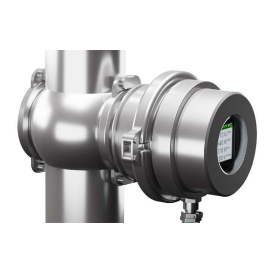
- Page 1 Operating Manual In-line turbidimeter TurBiScat 2 Ex 16108EN/1 SIGRIST-PHOTOMETER | 05-2022...
- Page 2 Unauthorised modifications © Copyright provisions (Copyright This document was written by SIGRIST-PHOTOMETER AG. The copyright© is held by SIGRIST-PHOTOMETER AG. Copying, changing or translating the contents as well as passing it on to third parties may only be done with the consent of SIGRIST-PHOTOMETER AG.
-
Page 3: Table Of Contents
7.1 Operation on TurBiScat 2 Ex ...................... 20 7.1.1 Operating elements............................ 20 7.2 Operation SIGRIST-Webinterface ....................... 21 7.2.1 Most important operating elements in measuring mode (SIGRIST-Webinterface).......... 21 8 Commissioning ........................... 22 9 Settings............................ 24 9.1 Displays on the TurBiScat 2 Ex ...................... 24 9.2 SIGRIST-Webinterface........................ 28... - Page 4 Table of contents 9.2.1 Homepage .............................. 28 9.2.2 Getting started in the SIGRIST web interface.................... 28 9.2.3 Save/Refresh Settings............................ 29 9.2.4 Change configuration mode .......................... 29 9.3 Simple configuration mode ....................... 30 9.3.1 Menu: Configuration ............................. 30 9.3.2 Menu: Simulation ............................ 32 9.3.3...
- Page 5 Table of contents 12.1 Replace basic device ......................... 63 13 Returns ............................ 64 14 Decommissioning/ Storage ...................... 65 15 Disposal ............................ 66 SIGRIST-PHOTOMETER 5 / 68...
-
Page 6: About This Document
NOTE Non-compliance with the instruction manual SIGRIST-PHOTOMETER AG accepts no liability for damage resulting from failure to observe the in- struction manual. Storage of the instruction manual The instruction manual is an integral part of the device. It must be available to staff at all times. - Page 7 Function read-only The menu function currently described is read-only. «Menu» Menu «Menus» or «functions» included in the software. Button Buttons used for navigation in the SIGRIST web user [Ok] interface. Placeholder Stands as a placeholder for unspecified, changing Device-specific term.
-
Page 8: Your Safety
Your Safety Your Safety Intended use The TurBiScat 2 Ex is designed for turbidity measurement in liquids in explosion hazard areas of zone 1 (Ex db IIC T3/T4/T5/T6 Ga/Gb). Possible applications can be found in the following areas: Areas of application... -
Page 9: Residual Risks
The use of aggressive cleaning agents may damage components of the device. Do not use aggressive chemicals or solvents for cleaning. If the device has nevertheless come into contact with aggressive chemicals, check it immediately for damage. SIGRIST-PHOTOMETER 9 / 68... - Page 10 Unauthorised access to the Internet by third parties can change the configuration and therefore faulty measurements cannot be ruled out. Ensure compliance with the safety measures on the part of the operator to prevent unauthorised Internet access. 10 / 68 SIGRIST-PHOTOMETER...
-
Page 11: Device Data
Device data Device data General view measuring station Explosive area TurBiScat 2 Ex WLAN connection WLAN input device explosion tested Operating device or control system Non explosive area Connecting cable explosion-protected Earth conductor terminal Nameplate Manufacturer Device type Serial number... -
Page 12: Scope Of Supply And Accessory Parts
Scope of supply and accessory parts Please refer to the sales documents for the detailed scope of supply. Standard scope of supply Designation Variant View ® TurBiScat 2 Ex VARINLINE connection Flange connection ® Blanking plate with cone and O- VARINLINE... -
Page 13: Specification Sheet
(Tenv.). The shaded area indicates the temperatures above which cooling by means of an optional cooling ring is required. The flow must be at least 0.2 l/min. at a coolant temperature of max. 20 °C. SIGRIST-PHOTOMETER 13 / 68... - Page 14 Device data Photometer Values Max. pressure TurBiScat 2 Ex (window insert): 2 MPa (20 bar) at max. 180 °C. ® VARINLINE connection with blanking plate (art. no.: 122037): Note specification. Flange connection with special measuring cell: 2 MPa (20 bar) at max.
- Page 15 Device data Module Values EG_POE: Ethernet LAN connec- Ethernet according to 10/100BaseT tion with Power over Ethernet POE according to 802.3af, class 0 SIGRIST-PHOTOMETER 15 / 68...
-
Page 16: Mounting
Fasten the photometer crosswise to the special measuring cell (3) with 4 screws Tighten the screws (tightening torque min. 30 Nm, max. 35 Nm). Ensure that the groove points in the flow direction. 16 / 68 SIGRIST-PHOTOMETER... -
Page 17: Connecting The Cooling Unit
Ensure coolant flow from bottom to top. Ensure a flow rate of min. 0.2 l/min. Mount coolant supply line to the inlet Mount coolant return line to the outlet Open the coolant supply line and check for tightness. SIGRIST-PHOTOMETER 17 / 68... -
Page 18: Electrical Installation
Function RS485 Modbus RTU * Digital input 5-28 VDC Digital output "High Side Switch" max. 20 mA Power output terminal 0/4...20 max. 700 Ω * with or without 120 Ω termination (configurable) 18 / 68 SIGRIST-PHOTOMETER... -
Page 19: Connection At A Distance
With the standard cable (0.2 mm ) maximum distances of 100 m are possible. For longer distances, the cable cross-section must be increased to such an extent that the cable resistance does not exceed 10 ohms. SIGRIST-PHOTOMETER 19 / 68... -
Page 20: Operation
Operation The device can be operated via the proximity sensor (TOUCH) with the finger directly on the device display or with WLAN-capable devices. Operation on TurBiScat 2 Ex 7.1.1 Operating elements You can switch between the different menu items by touching them. -
Page 21: Operation Sigrist-Webinterface
Operation Operation SIGRIST-Webinterface 7.2.1 Most important operating elements in measuring mode (SIGRIST-Webinterface) Menu Settings Status line Current status Measured values Current measured values 7 days logger Opens logger diagramme in window LED-Temp LED temperature Indoor temp Current internal temperature in the sensor... -
Page 22: Commissioning
ð The mobile device is connected to the photometer via WLAN. Alternatively, the QR code can be scanned to connect the mobile device to the WLAN. Open the SIGRIST web interface Open Internet browser (e.g. Chrome, Safari). Enter the displayed URL (192.168.10.1). ð Login screen appears. Alternatively, the QR code can be scanned to ac- cess the URL. - Page 23 Commissioning Login to SIGRIST web user interface Log in without password with [Sign in] . We recommend to secure the access to the SIGRIST web interface with a password. SIGRIST-PHOTOMETER 23 / 68...
-
Page 24: Settings
Settings Settings Displays on the TurBiScat 2 Ex Detailed information on how to navigate between the menus can be found Operation on TurBiScat 2 Ex [} 20] Start-up display 0/ 1 If necessary, the display can be rotated to the de- sired position while the start-up display appears. - Page 25 Configured channels: Channel designation with current measured value, unit and displayed measuring range. WLAN 2/ 1 Used to establish a WLAN connection during commissioning. Detailed information can be found here: Commissioning [} 22] SIGRIST-PHOTOMETER 25 / 68...
- Page 26 Supplier name: Name of the supplier Supplier address: Individual postal address of the supplier Telephone number: Individual telephone num- ber of the supplier Email address: Individual email address of the supplier Manufacturing company: Manufacturer of the device 26 / 68 SIGRIST-PHOTOMETER...
- Page 27 System info 4/ 2 Designation: System info Position indicator: Serves for orientation. Device type Serial number Designation of the measuring point or unit Oper. hours: Operating hours (h) Software version: Main controller Communication controller Sensor controller SIGRIST-PHOTOMETER 27 / 68...
-
Page 28: Sigrist-Webinterface
Settings SIGRIST-Webinterface 9.2.1 Homepage After connecting to the WLAN access point and logging on to the homepage, the SIGRIST-Webinter- face appears in measuring mode. [Menu]: Main menu [Settings]: Menus for the photometer Simple mode [} 30] Advanced mode [} 34] Menu structure: Simple mode [} 30]... -
Page 29: Save/Refresh Settings
Parameters are loaded from the photometer and unsaved changes are reset to the previous state. 9.2.4 Change configuration mode Set the toggle switch from Simple vanced or from Advanced to Simple. w The corresponding menu structure pears. SIGRIST-PHOTOMETER 29 / 68... -
Page 30: Simple Configuration Mode
«Access code» Enter access code (numbers only). Used to protect against unauthorised access. «Designation» Enter the designation of the measuring point identification in the SIGRIST web interface (max. 13 characters). Communication module EG_IO This parameter is only available with integrated communication module EG_IO. - Page 31 Displays the MAC address of the LAN access point. «DHCP» Yes/ No Automatic assignment of IP addresses. «IP address» XXX.XXX.XXX.XXX 0.0.0.0 Enter IP address. «Gateway addr.» XXX.XXX.XXX.XXX 0.0.0.0 Enter gateway address. «Sub-net mask» XXX.XXX.XXX.XXX 0.0.0.0 Enter subnet mask. SIGRIST-PHOTOMETER 31 / 68...
-
Page 32: Menu: Simulation
Triggers the adjustment. Calculates a new correction factor from the actual and nominal val- ues. «Act.corr» 0.500 ... 2.000 1.000 Specifies the current correction factor, which corrects the deviation from the factory calibra- tion. 9.3.4 Menu: History History\ Fault 32 / 68 SIGRIST-PHOTOMETER... -
Page 33: Menu: System Info
Software version of the sensor controller. «Version Comm» Software version of the communication controller. «Version Web» Software version of the interface for the SIGRIST web interface. «Update Firmware» [Browse...] [Upload & update] [Browse]: Select new firmware/ [Upload & update]: Upload firmware to sensor. -
Page 34: Advanced Configuration Mode
The assigned functions vary depending on the selection of pin 1 ... 6. Function Pin 1 Pin 2 Pin 3 Pin 4 Pin 5 Pin 6 Modbus RTU 120 Ω RS485 A RS485 B Modbus RTU RS485 A RS485 B 34 / 68 SIGRIST-PHOTOMETER... - Page 35 Set the baud rate of the Modbus interface (baud rate in bits/s). «Parity» None/ Even/ Odd None Set the parity bits of the Modbus interface. «Stop bit» 1/ 2 Set the number of stop bits of the Modbus interface. SIGRIST-PHOTOMETER 35 / 68...
- Page 36 Digital output\ limit value (pin 1 ... 4) This function only appears if the limit value has been activated in the "Digital output" function. Parameter Values Default value «Source» C1 ... Cn/ M1 ... Mn/ Humidity C1 Turb90 Available sources. 36 / 68 SIGRIST-PHOTOMETER...
-
Page 37: Menu: Wlan
Enter the password for the WLAN access point. WLAN\ WLAN connection Parameter Values Default value «Active» Yes/ No Switch the WLAN connection on/off. After activating, the device must be restarted. «MAC address» F0:26:4C:XX:XX:XX Device-specific Displays the MAC address of the WLAN connection. SIGRIST-PHOTOMETER 37 / 68... -
Page 38: Menu: Display
NOTICE! Low brightness reduces power consumption and extends the life of the display. «Power-saving mode» 0 ... 65535 s 300 s Time period after which the display brightness on the photometer is reduced without manip- ulation. 38 / 68 SIGRIST-PHOTOMETER... -
Page 39: Menu: Sensor Check
(mandatory operation). This prevents the measuring device from remaining in service mode for any length of time and no relevant measured value/ limit value being output. «Date format» DD.MM.YYYY/ DD.MM.YYYY DD/MM/YYYY/ MM/DD/YYYY Set the format of the date. SIGRIST-PHOTOMETER 39 / 68... -
Page 40: Menu: Meas. Channels
Set daylight saving time. For Europe, daylight saving time is set on the last Sunday in March and winter time on the last Sunday in October. «Contact information» SIGRIST-PHOTOMETER Enter line 1 of the contact information (max. 47 characters). «Contact information»... -
Page 41: Menu: Math. Channels
0 ... 90 %. «Name» Math Enter the name to identify this channel (max. 7 characters). «Unit» Enter the unit (max. 7 characters). «Coeff. a/b/c/d» 0000 Set the coefficient value a/b/c/d within the function. SIGRIST-PHOTOMETER 41 / 68... -
Page 42: Menu: Measuring Info
Detail: Percentage of all measuring points displayed on the graph. Values: Determines whether the curves represent minimum, maximum or average values. Cursor position Set the time of the measured value display. Cursor position is changed by mouse movement. 42 / 68 SIGRIST-PHOTOMETER... -
Page 43: Field Bus
EXTERNAL (43) can be configured by the user as a warning, fault or prioritised fault. 9.6.3 Modbus RTU/ TCP 9.6.3.1 Modbus RTU general For the connection via Modbus RTU the EG_IO module must be integrated. The Modbus RTU interface must be activated in the menu: «IO configuration» and parameterised. SIGRIST-PHOTOMETER 43 / 68... - Page 44 4 bits 15-0 30010 0x0009 Real 32-bit Intel single precision bits 31-16 30011 0x000A Real 32-bit Intel Measured value single precision channel 5 bits 15-0 30012 0x000B Real 32-bit Intel single precision bits 31-16 44 / 68 SIGRIST-PHOTOMETER...
-
Page 45: Modbus Tcp General
Modbus TCP communication runs on port 502. Only one Modbus TCP connection may exist at a time. An unused connection is automatically discon- nected after one minute. address table [} 44] and valid functions are the same as for Modbus RTU. SIGRIST-PHOTOMETER 45 / 68... -
Page 46: Servicing
CAUTION Equipment damage due to lack of servicing Missing or insufficient servicing as well as the use of non-original SIGRIST spare parts can lead to in- strument damage and measurement errors. Always carry out servicing work according to the servicing schedule. -
Page 47: Replace Desiccant
Loosen and remove the clamp ring (3) Remove basic unit (1) from the sensor head. Replace seal (6) Replace desiccant (7) Reassemble the device immediately in reverse order. Note the alignment of the groove with pin (2) SIGRIST-PHOTOMETER 47 / 68... -
Page 48: Clean Sensor Head
Drain process line (3). Remove clamp ring (2). Remove photometer from the process line. Clean sensor head Clean the three windows (1), (2), with a mild, abrasive-free cleaning agent (e.g. alcohol or soap) and a soft, lint-free cloth. 48 / 68 SIGRIST-PHOTOMETER... -
Page 49: Cleaning The Sensor Head (Flange Connection)
Drain process line (2). Loosen four screws (3). Remove photometer from process line (2). Clean sensor head Clean the three windows (1), (2), with a mild, abrasive-free cleaning agent (e.g. alcohol or soap) and a soft, lint-free cloth. SIGRIST-PHOTOMETER 49 / 68... -
Page 50: Calibration Check
DANGER Formazine (hydrazine sulphate) may cause skin or eye damage. Unprotected skin or eye contact with formazine may cause skin or eye damage. Wear protective goggles and gloves. Wash hands after work. 50 / 68 SIGRIST-PHOTOMETER... -
Page 51: Overview Of Control Units
(e.g. alcohol). Put the protective cover on the control unit and store it in the case. The control unit must be stored away from dirt, moisture, frost and temperatures above +80 °C. SIGRIST-PHOTOMETER 51 / 68... -
Page 52: Carry Out Calibration Check With Control Unit
Use a mobile device to connect to the device via WLAN (Commissioning [} 22]). Place the device on a soft and flat surface with the display facing downwards (NOTICE! do not place the device on a metal plate as this will interrupt the WLAN connection). 52 / 68 SIGRIST-PHOTOMETER... - Page 53 Put on control unit Align bolt with groove (2). Place the control unit on the photometer. ® Fastening the control unit (VARINLINE connection) Fasten control unit to photometer with clamp ring (2). SIGRIST-PHOTOMETER 53 / 68...
- Page 54 Adjustment with formazine (C1, C2): Enter the value of the formazine solution in the «Nom. val.»menu. Zero point adjustment (C3, C4): Enter value 0 in the «Nom. val.» menu. Press [initiate]. 54 / 68 SIGRIST-PHOTOMETER...
- Page 55 (1). Observe the alignment of the bolts on the solid refer- ence (2). (Only carry out this step if necessary). Cleaning the control unit [} 51]. w The calibration check is completed. SIGRIST-PHOTOMETER 55 / 68...
-
Page 56: Replace Seals
Secure the blanking plate with the clamp ring (3). ® Installing the photometer on the VARINLINE connection Fit the photometer including seal with ® clamp ring on VARINLINE connection (3). Ensure that the groove points in the flow direction. 56 / 68 SIGRIST-PHOTOMETER... -
Page 57: Replace Seal (Flange Connection)
4 screws (4). Tighten the screws (tightening torque min. 30 Nm, max. 35 Nm). Ensure that the groove points in the flow direction. 10.6 Spare parts Article number Designation Comments 122295 Desiccant and seal SIGRIST-PHOTOMETER 57 / 68... - Page 58 O-ring silicone 100x2, 70 Shore with optional cooling unit 2x 122296 Blanking plate with cone and O-ring FPM for VARINLINE housing 109440 Locking ring for in-line housing 122297 Screws and washers for flange Set of 4 connection 58 / 68 SIGRIST-PHOTOMETER...
-
Page 59: Troubleshooting
Make sure that the sample to be measured corresponds to the op- wrong erating conditions. Adjust calibration. Check the correct mounting of the device. Ensure that the maintenance work has been carried out in accor- dance with the Servicing schedule. Perform sensor check. SIGRIST-PHOTOMETER 59 / 68... -
Page 60: Warning/Error/Priority Messages
Input voltage is outside the Operating voltage is faulty permissible range (24 VDC) ADJUSTMENT Adjustment of the device could Device is soiled not be carried out Nominal value for adjustment does not match the value of the medium 60 / 68 SIGRIST-PHOTOMETER... -
Page 61: Fault Messages
Contact service engineer sible range MEASURING FAULT Measurement value acquisition Instrument not in process line is disturbed Air bubbles present in the medium Extraneous light near the measuring point (e.g. sight glass) Defective electronics Contact service engineer SIGRIST-PHOTOMETER 61 / 68... -
Page 62: Prio Fault Messages
Contact service engineer CRC USER An error was detected when Defective electronics checking the user data Contact service engineer CRC DISPLAY An error was detected when Defective electronics checking the display data Contact service engineer 62 / 68 SIGRIST-PHOTOMETER... -
Page 63: Repairs
Loosen and remove the clamp ring (3) Remove the old basic device from the sen- sor head. Replace seal (6) Insert new desiccant in new basic device. Reassemble new device immediately in reverse order. Note the alignment of the groove with pin (2) SIGRIST-PHOTOMETER 63 / 68... -
Page 64: Returns
Returns Return to the appropriate country representative For all devices and spare parts that are returned, a completed RMA form must be sent to the respon- sible SIGRIST-PHOTOMETER AG country representative (RMA form 14711E can be downloaded from www.photometer.com DANGER Residues of hazardous media Depending on the area of application, a dismantled device may contain residues of hazardous media. -
Page 65: Decommissioning/ Storage
All components that come into contact with the medium during operation must be dry and clean for long-term storage. All components must be protected from the effects of weather, condensing humidity and aggressive gases during storage. SIGRIST-PHOTOMETER 65 / 68... -
Page 66: Disposal
Battery Lithium Recycling via locally organised collection points Photometer housing Stainless steel plus in combina- Scrap metal collection points tion with glass Desiccant Ruby gel CRISTAL-GEL Normal waste disposal (chemi- cally harmless) 66 / 68 SIGRIST-PHOTOMETER... - Page 67 16108EN/1 67 / 68 SIGRIST-PHOTOMETER...
- Page 68 Your service partner SIGRIST-PHOTOMETER AG Hofurlistrasse 1 CH-6373 Ennetbürgen, Switzerland Tel. +41 (0)41 624 54 54 Fax. +41 (0)41 624 54 55 www.photometer.com info@photometer.com Operating Manual TurBiScat 2 Ex EN...
Need help?
Do you have a question about the TurBiScat 2 Ex and is the answer not in the manual?
Questions and answers