
Subscribe to Our Youtube Channel
Related Manuals for SIGRIST AquaMaster


Summary of Contents for SIGRIST AquaMaster
- Page 1 Document number: 13280E Version: 2 Valid from: S/N 379047 / SW V128 INSTRUCTION MANUAL AquaMaster with SICON M Multi-Parameter Measuring System...
- Page 2 Copyright© SIGRIST-PHOTOMETER AG, subject to technical changes without notice 7/2017 SIGRIST-PHOTOMETER AG Tel. +41 41 624 54 54 Hofurlistrasse 1 +41 41 624 54 55 CH-6373 Ennetbürgen info@photometer.com Switzerland www.photometer.com...
-
Page 3: Table Of Contents
Meaning of the safety symbols ................. 9 1.14 Meaning of the pictograms ................10 Instrument overview ....................11 Overview of AquaMaster with SICON M ............11 Designation of the connection box ..............12 Designation of the SICON M ................13 Scope of supply and accessories..............14 AquaMaster technical data ................ - Page 4 9.10 Installing an unconfigured sensor..............81 9.11 Integrating sensors purchased afterwards ............83 9.12 Integrating ColorPlus 2 in the AquaMaster ............. 85 9.13 Clean the measuring cell block ............... 86 9.14 Changing the battery in the SICON ..............88 10 Troubleshooting ......................89 10.1...
- Page 5 Contents Instruction Manual AquaMaster 11 Customer service information ..................94 12 Decommissioning/storage .................... 95 13 Packaging/Transport/Returning ..................96 14 Disposal ........................97 15 Spare parts list ......................98 16 Appendix ........................100 17 Index ......................... 101 Makro 13280E/2...
- Page 6 Instruction Manual AquaMaster Contents This pa ge is inte ntionally bla nk Makro 13280E/2...
-
Page 7: General User Information
Compliance with the underlying directives and formity standards. Copyright provisions This document has been written by SIGRIST-PHOTOMETER AG. Copying or modifying the content or giving this document to third parties is permitted only with the express consent of SIGRIST-PHOTOMETER AG. Document storage location This document is part of the product. -
Page 8: Order Document
The most recent version of this document can be downloaded at www.photometer.com (first time registration required). It can also be ordered from a SIGRIST representative in your country ( Instruction Manual “Customer service information”). Proper use The AquaMaster is designed for measuring the pH, conductivity, redox and dissolved oxygen during water treatment and is optimized for the requirements that occur in water treatment plants with regard to measurement span and ambient conditions. -
Page 9: Dangers When Not Used Properly
The instrument is not properly mounted or set up. The instrument is not installed and operated in accordance with the Instruction Manual. The instrument has been operated with accessory parts which SIGRIST-PHOTOMETER AG has not expressly recommended. Improper changes to the instrument have been performed. -
Page 10: Meaning Of The Pictograms
Instruction Manual AquaMaster General user information 1.14 Meaning of the pictograms All pictograms used in this document are explained below: Additional information about the current topic. Practical procedures when working with the AquaScat. Manipulations on the touchscreen. The screenshot is an example and may differ from current device. -
Page 11: Instrument Overview
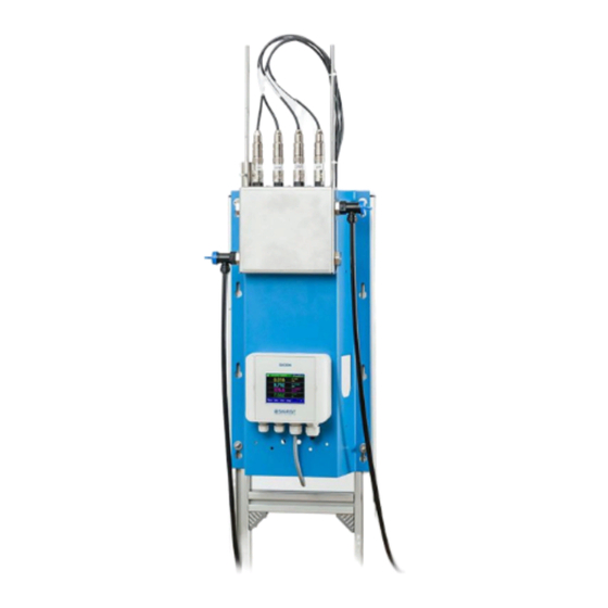
Instrument overview Instruction Manual AquaMaster Instrument overview Overview of AquaMaster with SICON M Figure 1: Instrument overview of AquaMaster with SICON M SICON M multi-channel control Sample media inlet unit Inlet regulator valve for measuring cell... -
Page 12: Designation Of The Connection Box
Instruction Manual AquaMaster Instrument overview Designation of the connection box The connection box is fitted with the following rating plate: Figure 2: Rating plate on connection box Manufacturer Country of origin Product name Serial number ... -
Page 13: Designation Of The Sicon M
Instrument overview Instruction Manual AquaMaster Designation of the SICON M The SICON M control unit is fitted with the following rating plate: Figure 3: Rating plate on SICON M Manufacturer Country of origin Product name Serial number ... -
Page 14: Scope Of Supply And Accessories
Instruction Manual AquaMaster Instrument overview Scope of supply and accessories Standard scope of supply for AquaMaster with SICON M 119494: PCS. ART. NO. NAME VIEW VARIANT 119494 Wall mount, com- plete with measur- ing cell block and SICON M control unit. - Page 15 Instrument overview Instruction Manual AquaMaster Optional accessory parts: PCS. ART. NO. NAME VIEW VARIANT 118442 Interface print Profibus DP 118445 Modbus RTU 119796 HART 119041 Current output 4-way module 119795 Current input 4-way module 118826 Ethernet cable IP66 for SICON (M)
- Page 16 Instruction Manual AquaMaster Instrument overview PCS. ART. NO. NAME VIEW VARIANT 119497 Oxygen sensor, VisiFerm DO Arc 120 initial equipment Sensor for measur- ing dissolved oxy- 119496 Redox sensor, ini- Polilyte Plus ORP tial equipment Arc 120 Sensor for measur-...
-
Page 17: Aquamaster Technical Data
55 x 115 x 40 cm (B x H x T) Service voltage 100 .. 240 VAC, 47 .. 63 Hz or 18 .. 30 VDC Power consumption 10W AquaMaster + 4 Sensors 25W AquaMaster + 4 Sensors + optional Photometer Weight ca.16 kg Protection class IP 54... -
Page 18: Technical Data Of The Sicon M
Instruction Manual AquaMaster Instrument overview Technical data of the SICON M SICON M DATA VALUES Service voltage and 9 .. 30 VDC; 5 W + photometer(s) power consumption Display ¼ VGA with touchscreen Resolution: 320 x 240 pixels with 3.5” diagonal... -
Page 19: Technical Data Of The Sensors
Instrument overview Instruction Manual AquaMaster Technical data of the sensors Conductivity sensor (Conducell 4USF Arc 120): DATA VALUES Sensor type Conductivity Measuring principle 4-pin measurement Measuring values Conductivity: µS/cm, mS/cm Temperature: °C, °K, °F Measuring range 1 .. 300,000 µS/cm Operating temperature -20 .. - Page 20 Instruction Manual AquaMaster Instrument overview Sensor Redox/ORP (Polilyte Plus ORP Arc 120): DATA VALUES Sensor type Redox/ORP Measuring principle Potential measurement Measuring values ORP: mV Temperature: °C, °K, °F Measuring range -1500 .. 1500 mV Operating temperature 0 .. 130 °C...
-
Page 21: General Safety Points
General safety points Instruction Manual AquaMaster General safety points Dangers during normal use Damage to the instrument or cabling. Touching damaged cables may lead to electric shocks resulting in death. The instrument may be operated only when the cables are undamaged. -
Page 22: Preventing Undesirable Online Access Attempts
Preventing undesirable online access attempts SIGRIST instruments are equipped with an integrated web user interface and Modbus TCP interface, thus offering state-of-the-art administration and control possibilities. However, if these are connected directly to the Internet, then any In- ternet user can in principle access your instrument and change the configuration. -
Page 23: Residual Risk
General safety points Instruction Manual AquaMaster Residual risk According to the risk assessment of the applied safety directive DIN EN 61010-1, there remains the risk of the displayed measuring values being incorrect. This risk can be reduced with the following measures: ... -
Page 24: Mounting
The system should not be exposed to direct sunlight during measurement; the measu- rement can be skewed by excessive external light. Mounting the base plate When mounting the base plate, refer to the AQUAMASTER/4-MB dimension drawing and the AQUAMASTER/6-MB drill plan. Grip the base plate only on the blue sheet. -
Page 25: Position Of The Connection Box
Mounting Instruction Manual AquaMaster Position of the connection box The connection box is positioned with the cable glands to the right between wall and base plate on the contact surface. The connection cables to the sensors are routed upward. The connection cable to the control unit is rou- ted downward. -
Page 26: Electrical Installation
Instruction Manual AquaMaster Electrical installation Electrical installation Safety pointers for electrical connection Connecting the service voltage. Improper connection of the electrical service voltage can be life-threatening. The system may also be damaged. Local regulations for electrical connections must be observed at all times. -
Page 27: Installation Of The Connection Box
Electrical installation Instruction Manual AquaMaster Installation of the connection box After installation has been made, stow away the connection box according to Section 4.3. WORKSTEP ADDITIONAL INFO / IMAGES When a service voltage of between 100 and 240 VAC is present, connect as fol-... -
Page 28: Installation Of The Sicon (M)
Instruction Manual AquaMaster Electrical installation Installation of the SICON (M) 5.3.1 Removing the cover from the SICON (M) WORKSTEP ADDITIONAL INFO / IMAGES Open the shutters. Loosen the fastening screws on the cover. Open the cover. Fasten the cover with the cover clamp. To do this, remove the cover clamp from the park po- sition (X) and fasten the cover in position (Y). -
Page 29: Overview Of The Opened Sicon Control Unit
Electrical installation Instruction Manual AquaMaster 5.3.2 Overview of the opened SICON control unit Figure 5: Overview of SICON Standard Park position for cover clamp microSD card (card for log data) USB connection Ethernet connection ... -
Page 30: Wiring The Sicon (M)
Instruction Manual AquaMaster Electrical installation 5.3.3 Wiring the SICON (M) Figure 6: SICON (M) terminal block Establish the electrical connections in the following sequence: TERMINAL MEANING REMARKS 1 .. 11 Terminals in SICON M: The cables with the colors Terminal... -
Page 31: Installation Of The Interfaces Prints (Field Bus Interfaces)
Electrical installation Instruction Manual AquaMaster Installation of the interfaces prints (field bus interfaces) 5.4.1 Overview of Modbus RTU and Profibus DP Figure 7: Overview of Modbus RTU and Profibus DP field bus interfaces Field bus interface (connection Field bus interface (connection print) print) for Profibus DP. -
Page 32: Implementation Of Hart
Instruction Manual AquaMaster Electrical installation 5.4.3 Implementation of HART To connect to HART, the optionally available HART module must be integrated in the SICON (M). The HART module must be activated in the Digi. interf./HART menu. With the activa- tion of HART, the Current ... - Page 33 Electrical installation Instruction Manual AquaMaster The burden on current output 1 can be between 230 and 500 Ohm for HART communica- tion. HART process Function Values variables Primary variable Measuring value Measuring value 1 channel 1 Secondary variable Measuring value...
-
Page 34: 4-Way Current Output
Instruction Manual AquaMaster Electrical installation 4-way current output The configuration of the 4-way current output module is described in the Reference Hand- book SICON M. Figure 9: Position of the 4-way current output 4-way current output Terminals The terminals of the 4-way current output are configured as follows:... -
Page 35: 4-Way Current Input
Electrical installation Instruction Manual AquaMaster 4-way current input The configuration of the 4-way current input module is described in the Reference Hand- book SICON M. Figure 10: Position of the 4-way current input 4-way current input Terminals The terminals of the 4-way current input are configured as follows:... -
Page 36: Fitting Sensors To The Measuring Cell Block
Instruction Manual AquaMaster Electrical installation Fitting sensors to the measuring cell block Damage to the sensors due to improper handling. pH sensors and Redox/ORP sensors must be carefully handled. pH sensors have a sensitive glass membrane; redox sensors have a very fine platinum wire at the measuring tip. These sensors can be damaged by carelessly touching the measuring tip, by improper cleaning. - Page 37 Electrical installation Instruction Manual AquaMaster WORKSTEP ADDITIONAL INFO / IMAGES Insert the sensor into the measuring cell block with the name (e.g. pH) facing forwards and then plug in without pressing too hard. When using pH or redox/ORP sensors, remove the lock cap first.
-
Page 38: Connecting The Water
Instruction Manual AquaMaster Electrical installation WORKSTEP ADDITIONAL INFO / IMAGES Fasten the connection cable to the right-hand bar with cable ties (arrows). Connecting the water WORKSTEP ADDITIONAL INFO / IMAGES Feed the outlet hose into the coupling on the water outlet (B) and engage by applying a little pressure. -
Page 39: Mounting The Optional Flow Meter
Electrical installation Instruction Manual AquaMaster Mounting the optional flow meter SIGRIST recommends installing a simple flow meter to regularly check the sample. Note the following points when mounting the flow meter: The flow meter is mounted in front of the measuring cell block. -
Page 40: Commissioning
Instruction Manual AquaMaster Commissioning Commissioning The initial start-up of the web user interface via the Ethernet interface is described in the Re- ference Manual. If malfunctions occur, consult the Section 10. Proceed with the initial start-up in accordance with the following table:... - Page 41 Commissioning Instruction Manual AquaMaster WORKSTEP ADDITIONAL INFO / IMAGES Establish service voltage to the system. 5.1: Establish service voltage to the connection box. The welcome screen appears on the display. The factory setting language is English. Ac- cordingly, the displayed language during the initi- al start-up is English.
-
Page 42: Operation
Instruction Manual AquaMaster Operation Operation Operation basics In this document we describe the practical examples only for the first steps of the menu con- figuration. All other setting options are described in the Reference Handbook. Operation us- ing the web user interface is described in detail in the Reference Manual. -
Page 43: Control Elements In Measuring Operation
Operation Instruction Manual AquaMaster Control elements in measuring operation Figure 11: Control elements in measuring operation Menu button Valu button Call up the menu structure. Numerical representation of the meas- Section 7.3 uring values. Section 7.4 ... -
Page 44: Info Button
Instruction Manual AquaMaster Operation Info button When you press the Info button, a general overview of the instrument settings appears. These are described below: 7.5.1 Page 1, Info button Figure 12: Info display Information about the current out- Status of the inputs ... -
Page 45: Info Button
Operation Instruction Manual AquaMaster 7.5.2 Page 2, Info button Figure 13: Info screen, page 2 Contact information Display of up to 5 pending fault mes- sages 13280E/2... -
Page 46: Info Button
Instruction Manual AquaMaster Operation 7.5.3 Page 3, Info button The state of all connected sensors is displayed here. Figure 14: Info screen, page 3 Sensor name Serial numbers of the corresponding sensor Fault message Section 10... -
Page 47: Diag Button
Operation Instruction Manual AquaMaster Diag button When you press the Diag button, a diagram appears which graphically shows the measuring values over a certain period of time. Figure15: Graphic representation of the measuring values Graphic representation of the... -
Page 48: Functions Of The Log Screen (Log Button)
Instruction Manual AquaMaster Operation Functions of the log screen (Log button) The screen logger works independently of the data logger, which is set in the Logger menu and writes to the microSD card. The screen logger records the data of the last 32 days in one minute intervals. The data can be called up from the Log menu. -
Page 49: Displays In Measuring Operation
Operation Instruction Manual AquaMaster Displays in measuring operation Figure 17: Displays in measuring operation Measuring value(s) Status line For values which are greater than In normal operation, the status line is the maximum measuring range, no green and shows the date and time. -
Page 50: Activating And Deactivating The Screen Lock
Instruction Manual AquaMaster Operation Activating and deactivating the screen lock MANIPULATION Press the lock icon top left. Within one second press the key bottom at the outside right. Depending on the initial state, the lock icon changes as follows: Display unlocked... -
Page 51: Switching To Service Operation
Operation Instruction Manual AquaMaster 7.10 Switching to service operation The system is configured in service operation. The measuring procedure is interrupted and the main menus appear on the display. Proceed as follows to access service operation: MANIPULATION ADDITIONAL INFO / IMAGES Press the Menu button. -
Page 52: Control Components In Service Mode
Page number / total number of pages Main menus Next page All of the AquaMaster functions are configured in the Local …… menu. Depending on the integrated sen- sors, the S 1 .. 8 (sensor 1 .. 8) menus appear here. -
Page 53: Numerical Entry
Operation Instruction Manual AquaMaster 7.11.2 Numerical entry The following screen is for entering numbers and data: Figure 19: Numerical entry Parameter name Entered values Prefix: For entering very large or Numerical entry very small values. This can be done as follows: 1. -
Page 54: Single Selection Of Functions
Instruction Manual AquaMaster Operation 7.11.3 Single selection of functions The single selection is identifiable by the ESC button below right. The currently selected function is green. Use the Up/Down arrows to navigate the options in long lists. Use the ESC button to cancel the entry. -
Page 55: Settings
Settings Instruction Manual AquaMaster Settings Setting the operating language MANIPULATION ADDITIONAL INFO / IMAGES Press the Menu button. Set access code and confirm with OK. Factory setting is 0. Press the Local ……. button. Press the Configuration button to access lan- If the desired menu does not guage selection. -
Page 56: Set Current Outputs
Instruction Manual AquaMaster Settings Set current outputs MANIPULATION ADDITIONAL INFO / IMAGES Press the Menu button. Set access code and confirm with OK. Factory setting is 0. Press the Local ……. button. Press the Curr. outputs button. If the desired menu does not appear, press the arrow key bottom right. -
Page 57: Set Limits
Settings Instruction Manual AquaMaster Set limits MANIPULATION ADDITIONAL INFO / IMAGES Press the Menu button. Set access code and confirm with OK. Factory setting is 0. Press the Local ……. button. If the desired menu does not appear, press the arrow key bottom right. -
Page 58: Upper And Lower Threshold Value Of A Limit
Instruction Manual AquaMaster Settings Upper and lower threshold value of a limit A maximum of eight limits with upper and lower threshold values can be programmed. If the operating mode is set to Exceeded, then while the upper threshold value is... -
Page 59: Set Outputs
Settings Instruction Manual AquaMaster Set outputs MANIPULATION ADDITIONAL INFO / IMAGES Press the Menu button. Set access code and confirm with OK. Factory setting is 0. Press the Local ……. button. Press the Inp./outputs button. If the desired menu does not appear, press the arrow key bottom right. -
Page 60: Setting The Measuring Channels And The Display
Instruction Manual AquaMaster Settings Setting the measuring channels and the display Setting of which channel should display the connected sensors MANIPULATION ADDITIONAL INFO / IMAGES Press the Menu button. Set the access code and confirm with OK. Factory setting is 0. - Page 61 Settings Instruction Manual AquaMaster MANIPULATION ADDITIONAL INFO / IMAGES Select the source of the measuring channel from the Source menu item. This name is dis- played to simplify identification of the measu- ring channel. The source defined under Channel 1 is displayed in the operation display at the top.
-
Page 62: Setting The Date And Time
Instruction Manual AquaMaster Settings Setting the date and time MANIPULATION ADDITIONAL INFO / IMAGES Press the Menu button. Set access code and confirm with OK. Factory setting is 0. Press the Local ……. button. Press the Configuration button. If the desired menu does not appear, press the arrow key bottom right. -
Page 63: Setting Or Changing The Access Code
Enter the access code and confirm with OK. Press the Meas button. Instrument again in measuring op- eration. A forgotten access code can be cleared only by a SIGRIST service engineer. Enter your personal access code here: 13280E/2... -
Page 64: Back Up Configured Data
Instruction Manual AquaMaster Settings 8.10 Back up configured data These measures can be of use to the service engineers for service purposes. MANIPULATION ADDITIONAL INFO / IMAGES Press the Menu button. Set access code and confirm with OK. Factory setting is 0. -
Page 65: Servicing
Servicing Instruction Manual AquaMaster Servicing Servicing schedule WHEN WHAT PURPOSE Every three Operator Cleaning, checking and, if Obligatory measure for main- months or as required, recalibration of taining measuring accuracy. needed the pH sensor. Section 9.5 Every three Operator Cleaning, checking and, if... -
Page 66: Introduction To Handling Of The Sensors
The calibration process is designed for use with Hamilton calibration solutions (500 ml con- tainer). Although it is possible to use other calibration solutions, SIGRIST-PHOTOMETER ex- pressly recommends using the Hamilton standards. The pH sensor is subject to two-point calibration. All other sensors are subject to single-point calibration. -
Page 67: Cleaning The Sensor Tips
Servicing Instruction Manual AquaMaster 9.2.3 Cleaning the sensor tips Damage to the sensors due to improper cleaning. Improper handling of the sensors when cleaning and the use of excessively aggressive clean- ing agents can lead to damage to the sensors. Note the following when cleaning the sen-... -
Page 68: Removing The Sensors
Instruction Manual AquaMaster Servicing Removing the sensors WORKSTEP ADDITIONAL INFO / IMAGES Close the inlet regulator valve (X) to the mea- suring cell block. Lift up the measuring cell block cover slightly and then unfold it. Swing the lock away from the measuring cell block by pressing the guide rod. -
Page 69: Installing The Sensors
Servicing Instruction Manual AquaMaster Installing the sensors WORKSTEP ADDITIONAL INFO / IMAGES Insert the sensor into the desired measuring position on the measuring cell block. The position of the sensors is not im- portant. However, it is better to install the pH... -
Page 70: Clean And Calibrate Ph Sensor
Instruction Manual AquaMaster Servicing Clean and calibrate pH sensor The pH sensor can be damaged through improper handling. The pH sensor can be damaged by carelessly touching the measuring tip or by using the wrong cleaning agent. For cleaning this sensor please consult Section 9.2. - Page 71 Servicing Instruction Manual AquaMaster WORKSTEP ADDITIONAL INFO / IMAGES 4.2: Submerge the pH sensor into the calibra- tion solution to the second notch. The sensor should be centered in the calibration beaker and is not permitted to contact the bottom of the calibration beaker.
- Page 72 Instruction Manual AquaMaster Servicing WORKSTEP ADDITIONAL INFO / IMAGES 5.3: Press the Initiate button. The recalibration begins. If the quality indication af- If the adjustment was successful, confirm with ter calibration is between 100 Adjustment OK. This completes the adjust- and 35, the age of the sensor is ment.
-
Page 73: Clean And Calibrate Conductivity Sensor
Servicing Instruction Manual AquaMaster Clean and calibrate Conductivity sensor The Conductivity sensor can be damaged through improper handling. The Conductivity sensor can be damaged by carelessly touching the measuring tip or by us- ing the wrong cleaning agent. For cleaning and calibrating this sensor please consult Section 9.2. - Page 74 Instruction Manual AquaMaster Servicing WORKSTEP ADDITIONAL INFO / IMAGES 4.2: Submerge the Conductivity sensor into the calibration solution to the second notch. The sensor must be centered in the cal- ibration beaker and is not permitted to con- tact the bottom of the calibration beaker.
- Page 75 Servicing Instruction Manual AquaMaster WORKSTEP ADDITIONAL INFO / IMAGES 5.3: Press the Initiate button. The recalibration If the quality indication af- begins. ter calibration is between 100 If the adjustment was successful, confirm with and 35, the age of the sensor is Adjustment OK.
-
Page 76: Clean And Calibrate Redox/Orp Sensor
Instruction Manual AquaMaster Servicing Clean and calibrate Redox/ORP sensor The Redox/ORP sensor can be damaged through improper handling. The Redox/ORP sensor can be damaged by carelessly touching the electrode or by using the wrong cleaning agent. For cleaning this sensor please consult Section 9.2. - Page 77 Servicing Instruction Manual AquaMaster WORKSTEP ADDITIONAL INFO / IMAGES 4.2: Submerge the Redox/ORP sensor into the calibration solution to the second notch. 5.1: Compare the Nom. val. (circle) with the value on the calibration solution. Pressing the Nom. val. button (circle) causes a numerical entry field to appear where the nominal value can be adjusted.
- Page 78 Instruction Manual AquaMaster Servicing WORKSTEP ADDITIONAL INFO / IMAGES 5.3: Press the Initiate button. The recalibration If the quality indication af- begins. ter calibration is between 100 If the adjustment was successful, confirm with and 35, the age of the sensor is Adjustment OK.
-
Page 79: Cleaning And Calibrating The Oxygen Sensor
Servicing Instruction Manual AquaMaster Cleaning and calibrating the oxygen sensor The oxygen sensor can be damaged through improper handling. The oxygen sensor can be damaged by touching the electrode carelessly or by using incor- rect cleaning agents. See Section 9.2 for details on how to clean the sensor. - Page 80 Instruction Manual AquaMaster Servicing WORKSTEP ADDITIONAL INFO / IMAGES 4.1: Wait until the temperature (1) is stable. Recalibration is only made when the tempera- ture is stable. This can take slightly longer on the oxygen sensor. The oxygen sensor is calibrated to the oxygen content of the ambient air.
-
Page 81: Replace Sensors Configured By Sigrist
Install new sensor in accordance with Section 9.4. Put the system into operation again. 9.10 Installing an unconfigured sensor This process is only applicable if a new sensor has not been ordered from SIGRIST- PHOTOMETER. WORKSTEP ADDITIONAL INFO / IMAGES In the Local ……... - Page 82 Instruction Manual AquaMaster Servicing WORKSTEP ADDITIONAL INFO / IMAGES A system search is now carried out for connec- ted Hamilton sensors. As soon as a sensor is found, the type and slave number are display- ed (e.g. Oxygen, Slave no. 1).
-
Page 83: Integrating Sensors Purchased Afterwards
(max. 4), then note down the value entered under Code. With this code, you can request an activation code from your SIGRIST representative. After receiving the activation code, enter it under Key word. If the combination of code... - Page 84 Instruction Manual AquaMaster Servicing WORKSTEP ADDITIONAL INFOR / IMAGES When the number of sensors is increased, it makes sense to assign the highest slave num- ber to the new sensor. Only in this way do the measuring channel allocations of the existing sensors remain valid.
-
Page 85: Integrating Colorplus 2 In The Aquamaster
Servicing Instruction Manual AquaMaster 9.12 Integrating ColorPlus 2 in the AquaMaster WORKSTEP ADDITIONAL INFO / IMAGES Interrupt the service voltage. Connect the ColorPlus 2 cable in the connec- tion box. One of the five terminal blocks marked with Sensor can be used here. -
Page 86: Clean The Measuring Cell Block
Instruction Manual AquaMaster Servicing 9.13 Clean the measuring cell block Figure 24: Instrument overview of AquaMaster Inlet flow regulator valve for meas- Sensor positioned on locking device uring cell block Outlet regulator valve for measur- Measuring cell block ing cell block Damage to the measuring cell (PMMA) if wrong cleaning agent is used. - Page 87 Servicing Instruction Manual AquaMaster The following procedure describes how to clean the measuring cell block: WORKSTEP ADDITIONAL INFO / IMAGES Close main water supply. Remove all sensors from the measuring cell block and position in the locking device (Figure 24, pos. 2).
-
Page 88: Changing The Battery In The Sicon
Instruction Manual AquaMaster Servicing 9.14 Changing the battery in the SICON Life-threatening voltage inside the instrument. Connecting electrical lines can be extremely dangerous. Instrument parts may also be da- maged. Local regulations for electrical installations must be observed at all times. -
Page 89: Troubleshooting
Troubleshooting Instruction Manual AquaMaster 10 Troubleshooting 10.1 Pinpointing malfunctions DETECTABLE MALFUNCTION MEASURE No reading Check whether the supply voltage is connected. Fault message in the display Analyze the fault message according to Section 10.2 to Section 10.4. ... -
Page 90: Warning Messages And Effect On Operation
Instruction Manual AquaMaster Troubleshooting 10.2 Warning messages and effect on operation Warnings indicate an unusual state. WARNINGS If a warning occurs during operation, it has the follo- wing effects: The system continues to operate. However, the measuring results must be evaluated with caution. - Page 91 Troubleshooting Instruction Manual AquaMaster WARNING DESCRIPTION POSSIBLE CAUSES QUALITY A Hamilton sensor reports a The calibration was incorrectly quality value under 35%. performed or was faulty. If the fault continues after repeated cleaning and calibra- tion, the sensor (or cap on the oxygen probe) must be re- placed.
-
Page 92: Fault Messages And Effect On Operation
Instruction Manual AquaMaster Troubleshooting 10.3 Fault messages and effect on operation FAULT If a fault occurs during operation, it has the following effects: The measurement is canceled. The measuring values go to 0. When the Fault message appears, the color of the status display changes to red and the text de- scribes the fault in question. -
Page 93: Prioritized Fault Messages And Their Effect On Operation
When there is a prioritized fault, the cause of the malfunction is serious. A prio fault of the AquaMaster sets all measuring values to 0. A prio fault of a sensor/photometer sets the con- cerned measuring values to 0. -
Page 94: Customer Service Information
If this is not known, SIGRIST-PHOTOMETER AG customer service in Switzerland would be glad to provide you with a contact address. A current list of all SIGRIST country representatives is available in the Internet at www.photometer.com. Please have the following information ready when you contact a SIGRIST service point or customer service: ... -
Page 95: Decommissioning/Storage
Decommissioning/storage Instruction Manual AquaMaster 12 Decommissioning/storage The aim of decommissioning is to prepare the individual components of the system properly for storage. WORKSTEP ADDITIONAL INFO / IMAGES Interrupt the service voltage to the system. Stop the main water supply. Remove the cover from the SICON M and re- Section 4 move the electrical connections. -
Page 96: Packaging/Transport/Returning
All peripheral devices and accessory parts must be packaged separately and marked with the serial number of the AquaMaster (Section 2.2). This prevents confusion and mix-ups later while also making it easier to identify parts. ... -
Page 97: Disposal
Disposal Instruction Manual AquaMaster 14 Disposal Disposal of the system and its peripheral devices is to be carried out in compliance with re- gional statutory regulations. The system has no environmentally damaging sources of radiation. The materials listed be- low should be disposed of or recycled as described in the following table:... -
Page 98: Spare Parts List
Instruction Manual AquaMaster Spare parts list 15 Spare parts list The parts mentioned in this documentation and their article numbers are listed in the follow- ing table: ARTICLE NUMBER ARTICLE NAME REMARKS 119500 pH Sensor, replacement 119501 Redox sensor, replacement... - Page 99 Spare parts list Instruction Manual AquaMaster This pa ge is inte ntionally bla nk 13280E/2...
-
Page 100: Appendix
Instruction Manual AquaMaster Appendix 16 Appendix 13280E/2... - Page 101 Appendix Instruction Manual AquaMaster This pa ge is inte ntionally bla nk 13280E/2...
-
Page 102: Index
Instruction Manual AquaMaster Index 17 Index Access code, set ........... 63 Improper use ............9 Article numbers ............ 98 Incorrect use ............9 Initial start-up ............40 Installation, electrical ........... 26 Installing the sensors ........36, 69 Back up data ............64 Internet ............... - Page 103 Index Instruction Manual AquaMaster Technical data ............. 17 Technical data, SICON M ........18 Safety symbols ............9 Terminal block ............. 30 Scope of supply, optional ........15 Terms, glossary ............7 Scope of supply, standard ........14 Touchscreen ............42 SD card adapter ...........
- Page 104 SIGRIST-PHOTOMETER AG Tel. +41 41 624 54 54 Hofurlistrasse 1 +41 41 624 54 55 CH-6373 Ennetbürgen info@photometer.com Switzerland www.photometer.com...
Need help?
Do you have a question about the AquaMaster and is the answer not in the manual?
Questions and answers