
Related Manuals for SIGRIST AquaScat 2 P


Summary of Contents for SIGRIST AquaScat 2 P
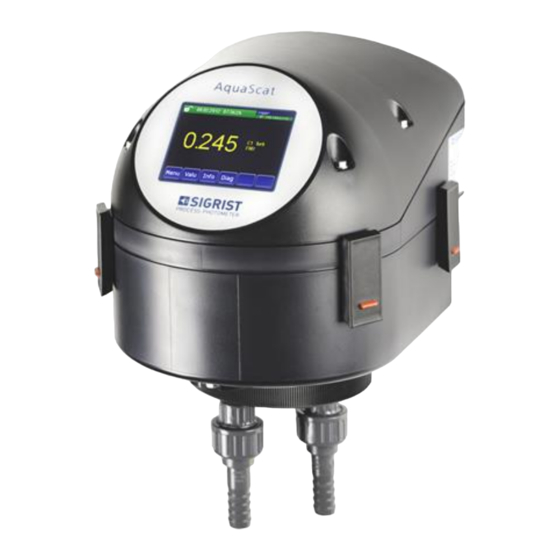
- Page 1 Document number: 11838E Version: 2 Valid from: V 126 Instruction Manual AquaScat 2 P Turbidimeter with closed flow cell...
- Page 2 Copyright© SIGRIST-PHOTOMETER AG, subject to technical changes without notice 4/2018 SIGRIST-PHOTOMETER AG Tel. +41 41 624 54 54 Hofurlistrasse 1 +41 41 624 54 55 CH-6373 Ennetbürgen info@photometer.com Switzerland www.photometer.com...
-
Page 3: Table Of Contents
1.12. Dangers when not used properly ..............3 Instrument overview ..................... 4 2.1. Measuring station with optional accessory parts ..........4 2.2. Designation of the AquaScat 2 P..............5 2.3. Scope of supply and accessory parts .............. 6 2.4. Technical data .................... 7 General safety pointers.................. - Page 4 Instruction Manual AquaScat 2 P 8.3. Remove the measuring cell unit ..............46 8.4. Replace desiccant ..................47 8.5. Manual adjustment ..................49 8.6. Check and clean optional accessory parts............52 8.7. Clean the closed measuring cell ..............52 8.8. Change battery ..................54 Troubleshooting ....................55 9.1.
-
Page 5: General Notes To The User
SP-C039 (mains device) SP-C039 (mains device). 1.4. Copyright stipulations The Instruction Manual has been written by SIGRIST-PHOTOMETER AG. Copying or modify- ing the content or providing this document to third parties is permitted only with the express written consent of SIGRIST-PHOTOMETER AG. -
Page 6: Meaning Of The Safety Symbols
Instruction Manual AquaScat 2 P General notes to the user 1.6. Meaning of the safety symbols Below is an explanation of all danger symbols that occur in this Instruction Manual. Danger due to electrical shock that may result in serious bodily injury or death. -
Page 7: Proper Use
Instruction Manual AquaScat 2 P 1.8. Proper use The AquaScat 2 P is designed for measuring turbidity during water treatment and is opti- mized for the values that occur in water treatment plants with regard to measurement span and environmental conditions. -
Page 8: Instrument Overview
Instruction Manual AquaScat 2 P Instrument overview Instrument overview 2.1. Measuring station with optional accessory parts Figure 1: Measuring station with optional accessory parts Sample outlet Section 4.4 Photometer with closed measuring cell Section 2.3 / 2.4 ... -
Page 9: Designation Of The Aquascat 2 P
Instrument overview Instruction Manual AquaScat 2 P 2.2. Designation of the AquaScat 2 P The photometer is fitted with a rating plate: Figure 2: Rating plate on the AquaScat 2 P Manufacturer Country of origin Product name Serial number ... -
Page 10: Scope Of Supply And Accessory Parts
Instruction Manual AquaScat 2 P Instrument overview 2.3. Scope of supply and accessory parts Scope of supply PCS. ART. NAME VIEW VARIANT AquaScat 2 P 24 118995 Photometer incl. docking station Documentation PCS. ART. NO. NAME VIEW VARIANT Instruction Manual... -
Page 11: Technical Data
Instrument overview Instruction Manual AquaScat 2 P PCS. ART. NO. NAME VIEW VARIANT 119102 Profibus DP bus cou- pler Reference Manual 119103 Modbus RTU bus cou- pler Reference Manual 119041 Module for 4 x current outputs 119045 24 VDC mains device... - Page 12 Instruction Manual AquaScat 2 P Instrument overview AQUASCAT 2 P VALUES Power consumption Curr. outputs 2 x 0/4 .. 20 mA, galvanically isolated to max. 50 V relative to ground, max. 600 burden Digital input Contact Analog inputs 2 x 0/4 .. 20 mA...
-
Page 13: General Safety Pointers
General safety pointers 3.1. What to do in an emergency What to do in an emergency: SIGRIST-PHOTOMETER AG instruments have no On/Off switch. This is the responsibility of CAUTION! the customer. Before commissioning, clarify the following points: Clarify the position of the On/Off switch and the way it works. -
Page 14: Dangers When Using Properly
Instruction Manual AquaScat 2 P General safety pointers 3.2. Dangers when using properly Electrical shock due to damaged instrument or cabling. The instrument may be operated only when the cables are undamaged. DANGER! The instrument may be operated only if it has been properly installed or repaired. -
Page 15: Warning And Danger Symbols On The Instrument
General safety pointers Instruction Manual AquaScat 2 P 3.3. Warning and danger symbols on the instru- ment There are no warning or danger symbols on the instrument. Users must ensure that they observe the safety measures as specified in the Instruction Ma n- WARNING! ual at all times when working with the instrument and its peripheral equipment. -
Page 16: Mounting The Measuring Device
Make sure that the photometer is not exposed to direct sunlight. This may cause sig- nificant deviations in the measuring value. 4.2. Mechanical mounting of the photometer Figure 3: Mounting the AquaScat 2 P Fastening on the photometer Mounting bracket on the wall ... - Page 17 Mounting the measuring device Instruction Manual AquaScat 2 P WORKSTEP PROCEDURE Pre-mounting the mounting Screw on the mounting bracket (Figure 3, 2) horizontally bracket. at the intended position. Fasten the photometer onto 2.1: Position the photometer on the pre-mounted the pre-mounted mounting mounting bracket (Figure 3, 2) and pay attention to the bracket.
-
Page 18: Mounting The Docking Station
Instruction Manual AquaScat 2 P Mounting the measuring device 4.3. Mounting the docking station Mount the docking station close to the photometer using two fastening screws. Figure 1, 6 4.4. Mounting the sample connections 4.4.1. Important information when mounting the sample... -
Page 19: Mounting The Optional Flow Meter
CAUTION! be checked about 2 weeks after installation to ensure that no air can be pulled in. SIGRIST recommends installing a simple flow meter to regularly check the sample flow . Sections 2.1 and 2.3 Note the following points when mounting the flow meter: The flow meter is to be fastened before the sample inlet of the photometer. -
Page 20: Electrical Installation
Instruction Manual AquaScat 2 P Electrical installation Electrical installation 5.1. Safety pointers for the installation Life threatening voltage inside the instrument: Connecting electrical lines is extremely dangerous. Parts of the system can also be damaged. Local regulations must be observed at all times for electrical installa tions. -
Page 21: Installation Procedure
Electrical installation Instruction Manual AquaScat 2 P 5.2. Installation procedure You can access the terminals by removing the front cover. Proceed as follows: WORKSTEP PROCEDURE Loosen the five screws on the front cover with a size 7 hex key. Remove the front cover. -
Page 22: Connecting The Customer Connections
Instruction Manual AquaScat 2 P Electrical installation 5.3. Connecting the customer connections Life threatening voltage inside the instrument: The photometer has no mains switch; hence the instrument is charged with voltage immedi- ately after being connected. DANGER! The cable lengths must be selected keeping in mind that the instrument will be mounted on the docking station. - Page 23 Electrical installation Instruction Manual AquaScat 2 P Establish the electrical connections in the following sequence: TERMINALS MEANING REMARKS 1 – 2 – 3 Output 1 (relay contact 1) The relay outputs can be freely con- figured. Section 7.11 4 – 5 – 6...
-
Page 24: Connection Of The Optional Mains Device
Instruction Manual AquaScat 2 P Electrical installation 5.4. Connection of the optional mains device Life threatening voltage inside the instrument: Connecting electrical lines is extremely dangerous. Local regulations for electrical installations must be observed at all times. DANGER! Figure 6: Optional power unit open ... - Page 25 Electrical installation Instruction Manual AquaScat 2 P Cable with an outer diameter of 4-8 mm must be used. Connecting the TERMINAL DESIGNATION CABLE TERMINAL DESIGNATION FUNCTION mains device: IN THE MAINS DEVICE COLOR IN THE PHOTOMETER +24 V Brown 8: 24V...
-
Page 26: Initial Start-Up
Instruction Manual AquaScat 2 P Initial start-up Initial start-up The initial start-up with the web user interface via the Ethernet interface is described in the Reference Manual. Proceed with the initial start-up in accordance with the following table. If malfunctions oc- cur, please refer to Section 9. - Page 27 Initial start-up Instruction Manual AquaScat 2 P WORKSTEP PROCEDURE 4.3: Measuring operation begins. Section 7.7 Set language. Section 7.8 Set current outputs. Section 7.9 Set limits. Section 7.10 Configure flow meter if present. Section 7.11 Set outputs 1 &...
-
Page 28: Operation
Use only slight pressure to perform manipulations on the touchscreen. Do not use chemicals or solvents to clean the touchscreen. The AquaScat 2 P has a touchscreen. It is operated by touching with your fingers. The navi- gation elements change color when touched. - Page 29 Operation Instruction Manual AquaScat 2 P 7.2.1. Menu button You reach the menu structure by pressing the Menu button and entering the access code. Now the instrument is in service operation. Operator prompting in service operation is des cribed in Section 7.6.
- Page 30 Instruction Manual AquaScat 2 P Operation 7.2.3. Functions of the log screen (Log button) The screen logger works independently of the data logger, which is set in the Logger menu and writes to the microSD card. The screen logger records the data of the last 32 days in one minute intervals. The data can be called up from the Log menu.
- Page 31 Operation Instruction Manual AquaScat 2 P 7.2.4. Valu button By touching the Valu field, a numerical measuring value appears on the display. Section 7.4 7.2.5. Info button When you press the Info button, a general overview of the s ettings and configurations of the photometer appears.
- Page 32 Instruction Manual AquaScat 2 P Operation Page 2: Figure 11: Info screen, page 2 Contact information Display of up to 5 pending fault messages 11838E/2...
-
Page 33: Activating And Deactivating The Screen Lock
Operation Instruction Manual AquaScat 2 P 7.3. Activating and deactivating the screen lock 1. Press the lock icon top left. 2. Within one second press the button bot- tom right. Depending on the initial state, the lock icon changes as follows:... -
Page 34: Display In Measuring Operation
Instruction Manual AquaScat 2 P Operation 7.4. Display in measuring operation The instrument is in measuring operation after it is switched on. The current measuring val- ues are continuously displayed. Figure 12: Displays in measuring operation Measuring value... -
Page 35: Switching To Service Operation
Operation Instruction Manual AquaScat 2 P 7.5. Switching to service operation Definition of service The photometer is configured in service operation. The measuring procedure is interrupted operation and the main menus appear on the display. Proceed as follows for service operation:... -
Page 36: Control Components In Service Operation
Instruction Manual AquaScat 2 P Operation 7.6. Control components in service operation 7.6.1. Entry element in service operation Figure 13: Menu structure Path specification Page number / total number of pages Main menus Next page Instrument-specific menus of the photometer. - Page 37 Operation Instruction Manual AquaScat 2 P 7.6.2. Numerical entry The following screen is for entering numbers and data: Figure 14: Numerical entry Display of the entered values. SI prefix: For entering very large or very small values. This can be done as follows: 1.
- Page 38 Instruction Manual AquaScat 2 P Operation 7.6.3. Single or multiple selection with scroll bar Single selection The single selection is identifiable on the ESC button below right The currently selected value is green. Use the Up/Down arrows to navigate the options in long lists. Use the ESC button to cancel the entry.
-
Page 39: Setting The Operating Language
Operation Instruction Manual AquaScat 2 P 7.7. Setting the operating language The following describes how to set the language of the menus and messages: MANIPULATION SUPPLEMENTARY INFORMATION Press the Menu button. Set the access code and confirm with OK. Factory setting is 0. -
Page 40: Setting The Current Outputs
Instruction Manual AquaScat 2 P Operation 7.8. Setting the current outputs MANIPULATION SUPPLEMENTARY INFORMATION Press the Menu button. Set the access code and confirm with OK. Factory setting is 0. Press the Curr. outputs button. Select current output 1 or 2. -
Page 41: Setting The Limits
Operation Instruction Manual AquaScat 2 P 7.9. Setting the limits So that the limits are not only displayed but also the outputs are switched, they have to be configured accordingly. Section 7.10 MANIPULATION SUPPLEMENTARY INFORMATION Press the Menu button. - Page 42 Instruction Manual AquaScat 2 P Operation Upper and lower A maximum of two limits with upper threshold value of a and lower threshold values can be limit. programmed. If the operating mode is set to Ex- ceeded, then while the upper thres h-...
-
Page 43: Configuring The Flow Meter
Operation Instruction Manual AquaScat 2 P 7.10. Configuring the flow meter The optional flow meter is connected to terminals 22, 23 (In1). Proceed as follows to activate monitoring: MANIPULATION SUPPLEMENTARY INFORMATION Press the Menu button. Set the access code and confirm with OK. -
Page 44: Setting The Outputs (Relay Outputs 1/2)
Instruction Manual AquaScat 2 P Operation 7.11. Setting the outputs (relay outputs 1/2) Outputs 1/2 are located on the base print of the customer connection terminals and are de s- ignated as relays 1/2. Section 5.3 MANIPULATION SUPPLEMENTARY INFORMATION Press the Menu button. -
Page 45: Setting The Date And Time
Operation Instruction Manual AquaScat 2 P 7.12. Setting the date and time MANIPULATION SUPPLEMENTARY INFORMATION Press the Menu button. Set the access code and confirm with OK. Factory setting is 0. Use the down arrow key to select the sec- ond page. -
Page 46: Setting Or Changing The Access Code
Press the Meas button. Instrument again in measuring opera- tion. A forgotten access code can be cleared only by a SIGRIST service engineer! Enter your access code: 7.14. Back up configured data These measures can be of use to the service engineers for service purposes. -
Page 47: Servicing
Servicing Instruction Manual AquaScat 2 P Servicing It is absolutely necessary to observe the following instructions when performing servicing duties: DANGER! Observe the safety pointers before performing servicing duties. The instrument must never be operated when the housing is removed. -
Page 48: Fasten Photometer To Docking Station
Instruction Manual AquaScat 2 P Servicing 8.2. Fasten photometer to docking station Figure 18: Photometer fastened to docking station Photometer Docking station Knurled screw for fastening the Mounting bracket for photometer in photometer measuring position 11838E/2... - Page 49 Servicing Instruction Manual AquaScat 2 P WORKSTEP PROCEDURE Interrupt sample supply to the photometer and wait until the measuring cell empties. Fasten photometer to the 2.1: Remove the photometer (Figure 18, 1) from the docking station. measuring position and place on the docking station Fig- ure 18, 2).
-
Page 50: Remove The Measuring Cell Unit
Instruction Manual AquaScat 2 P Servicing 8.3. Remove the measuring cell unit WORKSTEP PROCEDURE Section 8.2 Fasten photometer to the docking station. Loosen the five fastening screws of the measuring cell unit (circles). Loosen mounting clip and 3.1: Use a little force to push the red fuse in the direction... -
Page 51: Replace Desiccant
Servicing Instruction Manual AquaScat 2 P 8.4. Replace desiccant Figure 19: View of the measuring cell element Desiccant (4x) Measuring cell Support Measuring cell plate WORKSTEP PROCEDURE Interrupt the sample supply to the photometer. Remove sample connections and wait until the measuring cell empties. - Page 52 Instruction Manual AquaScat 2 P Servicing Re-fasten the measuring cell unit 5.1: Mount the measuring cell unit again on the to the optics unit. optics unit and lock with the mounting clips. Pay attention to the guide pins (arrows). 5.2: Fasten the measuring cell unit by tightening the five screws (circles).
-
Page 53: Manual Adjustment
Servicing Instruction Manual AquaScat 2 P 8.5. Manual adjustment The manual adjustment should be carried out after the measuring cell is cleaned. The fold-out Figure 20 is available in the Appendix to assist you when performing servicing duty. WORKSTEP PROCEDURE Interrupt the sample supply to the photometer. - Page 54 Instruction Manual AquaScat 2 P Servicing WORKSTEP PROCEDURE 3.2: Mount the checking unit (Figure 20, 1) onto the measuring cell plate (Figure 20, 4) as follows. 1. Align the groove (D) to the pin (C). 2. Press and hold the release device (A) and guide the checking unit onto the cam (B).
- Page 55 Servicing Instruction Manual AquaScat 2 P WORKSTEP PROCEDURE Fill the measuring cell with For turbidity values < 0.5 FNU water. If the water turbidity is less than 0.5 FNU, establish the sample feed and fill the measuring cell with water.
-
Page 56: Check And Clean Optional Accessory Parts
Instruction Manual AquaScat 2 P Servicing 8.6. Check and clean optional accessory parts Damage to components due to aggressive cleaning agents. Do not use aggressive cleaning agents when cleaning optional accessory parts. Commercially CAUTION! available dishwashing liquid can be used if needed. - Page 57 Servicing Instruction Manual AquaScat 2 P MANIPULATION SUPPLEMENTARY INFORMATION Loosen the screw cap (Figure 20, 3) and remove the measuring cell plate (Figure 20, 4). Clean the inside of the measuring cell (arrow) with a cotton cloth. Clean the measuring cell window with cotton tipped applicators and alco- hol.
-
Page 58: Change Battery
Instruction Manual AquaScat 2 P Servicing 8.8. Change battery Life threatening voltage inside the instrument: Connecting the electrical lines is extremely dangerous. Parts of the system can also be da m- aged. Local regulations must be observed at all times for electrical installations. -
Page 59: Troubleshooting
Troubleshooting Instruction Manual AquaScat 2 P Troubleshooting 9.1. Pinpointing the cause of a malfunction DETECTABLE MEASURES MALFUNCTION Check whether the service voltage is connected. Sec- No reading. tion 5 Check whether the fine-wire fuse in the instrument is OK. Section 9.2 Analyze the error message. -
Page 60: Warning And Error Messages
Instruction Manual AquaScat 2 P Troubleshooting WORKSTEP PROCEDURE Remove the old fine-wire fuse (circle) from the base print (AQBasi) and replace with a new one (type T2A). Carefully mount front cover and fasten with the five screws. Damage to the threaded inserts in... - Page 61 Troubleshooting Instruction Manual AquaScat 2 P The following warnings can be displayed: WARNING DESCRIPTION POSSIBLE CAUSES MESSAGE V IN The input voltage is outside the The service voltage is faulty. permitted range (18-30 VDC). ADJUSTMENT The adjustment of the instrument The instrument is soiled.
- Page 62 Instruction Manual AquaScat 2 P Troubleshooting The following error messages can be displayed: ERROR DESCRIPTION POSSIBLE CAUSES MESSAGE V ANALOG One of the internal analogue Defect in the electronic system. Service technician voltages is outside the permitted range. MEASUR.FAULT...
- Page 63 Troubleshooting Instruction Manual AquaScat 2 P 9.3.3. Prioritized error messages and their effect PRIO (PRIORITIZED FAULT): If a prioritized fault occurs during operation, it has the following effects: When there is a prioritized fault, the cause of the malfunction is serious.
-
Page 64: Customer Service Information
If this is not known, SIGRIST-PHOTOMETER AG customer service in Switzerland would be glad to provide you with a contact address. A current list of all SIGRIST country representatives is available in the Internet at www.photometer.com. Please have the following information ready when you contact a SIGRIST service point or customer service: The serial number of the photometer. -
Page 65: Decommissioning & Storage
Decommissioning & storage Instruction Manual AquaScat 2 P 11. Decommissioning & storage Life threatening voltage inside the instrument: Connecting the electrical lines is extremely dangerous. Parts of the system can also be dam- aged. Local regulations must be observed at all times for electrical installations. -
Page 66: Packaging & Transport
Instruction Manual AquaScat 2 P Packaging & transport 12. Packaging & transport The original packaging materials of the photometer should be used for packaging the pho- tometer and its peripheral components if possible. If the original packa ging is no longer... -
Page 67: Disposal
Disposal Instruction Manual AquaScat 2 P 13. Disposal Disposal of the photometer and its peripheral devices is to be carried out in compliance with regional statutory regulations. The photometer has no environmentally damaging sources of radiation. The materials listed below should be disposed of or recycled as described in the following table:... -
Page 68: Spare Parts
Instruction Manual AquaScat 2 P Spare parts 14. Spare parts The parts mentioned in this documentation and their article numbers are listed in the table below: ART.–NO. ARTICLE NAME REMARKS Section 8.4 111391 Desiccant bag, 30 g Section 9.2... -
Page 69: Measuring Cell Plate With Control Unit
Appendix Instruction Manual AquaScat 2 P 15.1. Measuring cell plate with control unit Figure 20: Overview of the closed measuring cell Checking unit Cam for fastening the checking unit. Screw cap for the fastening of the... - Page 70 Instruction Manual AquaScat 2 P Appendix 65 / 11838E/2...
-
Page 71: Servicing Log
Appendix Instruction Manual AquaScat 2 P 15.2. Servicing log Servicing log Serial number: First commissioning: Remarks: Adjustment value Recalibr.1 Completed servicing duties Date Initials Before After 11838E/2... - Page 72 Instruction Manual AquaScat 2 P Appendix 67 / 11838E/2...
- Page 73 Appendix Instruction Manual AquaScat 2 P 11838E/2...
-
Page 74: Index
Index Instruction Manual AquaScat 2 P 16. Index Access code, set ..........42 Limits, definition ..........38 Article numbers ..........64 Main switch............16 Back-up fuse .............16 Mains device connection ........ 20 Battery, SICON..........54 Mains switch ..........16, 18 Malfunctions ............ 16 Measuring cell..........65 Measuring error .........14, 15... - Page 75 Technical data............. 7 Valve ..............14 Terms, glossary ........... ii Transport............62 Warning symbols on the instrument ..... 11 Warnings ............56 Use restrictions ........... 3 Water flow rate ..........14 Web user interface .......... 22 What to do in an emergency ......9...
- Page 76 SIGRIST-PHOTOMETER AG Tel. +41 41 624 54 54 Hofurlistrasse 1 +41 41 624 54 55 CH-6373 Ennetbürgen inf o@photome ter. com Switzerland w w w .photome ter.com...
Need help?
Do you have a question about the AquaScat 2 P and is the answer not in the manual?
Questions and answers