
Subscribe to Our Youtube Channel
Related Manuals for SIGRIST OilGuard 2 Ex


Summary of Contents for SIGRIST OilGuard 2 Ex
- Page 1 Document number: 13003E Version: 3 Valid from: S/N 632 010 / SW V329 INSTRUCTION MANUAL OilGuard 2 Ex Fluorescence Measuring Instrument...
- Page 2 Copyright© SIGRIST-PHOTOMETER AG, subject to technical changes without notice 7/2019 SIGRIST-PHOTOMETER AG Tel. +41 41 624 54 54 Hofurlistrasse 1 +41 41 624 54 55 CH-6373 Ennetbürgen info@photometer.com Switzerland www.photometer.com...
-
Page 3: Table Of Contents
Safety pointers for the electrical connection ............ 34 Connecting the mains voltage to the Ex control unit ........35 Opening and closing the door on the OilGuard 2 Ex ........36 Adjusting the mains voltage on 115 VAC instruments ........37 Connecting the lines for data transmission ............. - Page 4 Instruction Manual OilGuard 2 Ex Contents Functions of the log screen (Log button) ............48 Displays in measuring operation..............49 Lock / unlock the touch screen................ 50 7.10 Switching to service mode ................51 7.11 Control components in service mode .............. 52 7.11.1...
- Page 5 Contents Instruction Manual OilGuard 2 Ex 13 Packaging / Transport / Returning ................98 14 Disposal ........................99 15 Spare parts list ......................100 16 Appendix ........................102 16.1 Service Record ....................102 17 Index ......................... 103 Makro 13003E/3...
- Page 6 Instruction Manual OilGuard 2 Ex Contents This pa ge is inte ntionally bla nk Makro 13003E/3...
-
Page 7: General User Information
Purpose of the Instruction Manual This Instruction Manual provides the user with helpful information about the entire life cycle of the OilGuard 2 Ex and its peripheral devices. Before commissioning the instrument, you should be completely familiar with the Instruction Manual. -
Page 8: Order Document
The most recent version of this document can be downloaded at www.photometer.com (first time registration required). It can also be ordered from a SIGRIST representative in your country ( Instruction Manual “Customer service information”). Proper use The OilGuard Ex and its peripherals are designed for measuring mineral oil traces or other fluorescent materials in aqueous solutions. -
Page 9: Dangers When Not Used Properly
The instrument is not properly mounted, set up or transported. The instrument is not installed and operated in accordance with the Instruction Manual. The instrument has been operated with accessory parts which SIGRIST-PHOTOMETER AG has not expressly recommended. Improper changes to the instrument have been performed. -
Page 10: Meaning Of The Pictograms
1.13 Meaning of the pictograms All pictograms used in this document are explained below: Additional information about the current topic. Practical procedures when working with the OilGuard 2 Ex. Manipulations on the touchscreen. The screenshot is an example and may differ from current device. -
Page 11: Instrument Overview
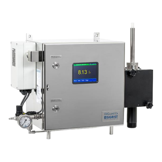
Instrument overview Instruction Manual OilGuard 2 Ex Instrument overview Overview of OilGuard 2 Ex Figure 1: Instrument overview of OilGuard 2 Ex OilGuard 2 Ex photometer with Ex control unit display (touchscreen) Large stand with adjustable pump... -
Page 12: Designation Of The Oilguard 2 Ex
Instruction Manual OilGuard 2 Ex Instrument overview Designation of the OilGuard 2 Ex The photometer is fitted with the following rating plate: Figure 2: Rating plate on OilGuard 2 Ex Manufacturer Country of origin Product name Serial number ... -
Page 13: Scope Of Supply And Accessories
Instrument overview Instruction Manual OilGuard 2 Ex Scope of supply and accessories Standard scope of supply for the OilGuard 2 Ex: PCS. Art. no. Name View Variant 119552 Ex housing with 230 VAC photometer and integrated operat- ing unit 119553... - Page 14 Instruction Manual OilGuard 2 Ex Instrument overview Optional accessory parts: PCS. Art. no. Name View Variant 119745 Sample prepara- tion system for PVDF measuring cell 119810 Sample prepara- tion system for VA measuring cell (incl. piping for sample prepara- tion, connecting...
- Page 15 Instrument overview Instruction Manual OilGuard 2 Ex PCS. Art. no. Name View Variant 119816 Piping for com- pressed air on pump 119805 Large stand 119813 Pump bracket Can only be used together with the stand. 119804 Wall bracket (incl. screws)
-
Page 16: Technical Data
Instruction Manual OilGuard 2 Ex Instrument overview Technical data DATA VALUES Measuring principle Fluorescence measurement Measuring scope 0 .. 0.1 FLU / 0 .. 100 FLU Measuring ranges 8 ranges (freely configurable for different types of oil) Sample medium Aqueous solutions with traces of mineral oil or other fluorescent materials ... - Page 17 Instrument overview Instruction Manual OilGuard 2 Ex DATA VALUES Sample pressure See measuring cell Housing material Stainless steel 1.4404 / 316L Quality of compressed Instrument air, ISO 8573-1:2010 [1:3:1] Compressed air con- At least 1.5 bar, minimum flow rate during purging 54 l/min, con- sumption sumption during operation 5.5 l/min...
-
Page 18: General Safety Points
Instruction Manual OilGuard 2 Ex General safety points General safety points Dangers during normal use Opening the photometer in potentially explosive areas. Opening the photometer in potentially explosive areas can lead to an explosion. The instrument may be opened only after the service voltage has been interrupted and a period of at least ten minutes has elapsed. -
Page 19: Residual Risk
General safety points Instruction Manual OilGuard 2 Ex Moisture and condensation on electronic components during servicing duties. The photometer may be damaged if moisture enters the inside of the instrument. Work inside the instrument may only be carried out in dry conditions. In doing so, the... -
Page 20: Preventing Undesirable Online Access Attempts
General safety points Preventing undesirable online access attempts SIGRIST instruments are equipped with an integrated web user interface and Mod- bus TCP interface, thus offering state-of-the-art administration and control possibil- ities. However, if these are connected directly to the Internet, then any Internet us- er can in principle access your instrument and change the configuration. -
Page 21: Mounting
Mounting Instruction Manual OilGuard 2 Ex Mounting Location selection Note the following points for the operating location: The electrical supply must be ensured. The purging air/compressed air connection must be ensured. The sample feed must be ensured as described in the technical data. -
Page 22: Mounting Variations
Instruction Manual OilGuard 2 Ex Mounting Mounting variations When fastening the mounting devices and mounting the photometer, refer to the corre- sponding OILGUARD 2/IECEx/…-MB dimension drawing. SIGRIST-PHOTOMETER AG supports the following four mounting types: Stand mounting Mounting with Mounting with Direct wall... -
Page 23: Mounting The System
Mounting Instruction Manual OilGuard 2 Ex Mounting the system Explosion hazard due to static discharge of the pumps. Static discharges can occur when the pumps are in operation. This can lead to explosions. The pumps must be connected to earth. - Page 24 Instruction Manual OilGuard 2 Ex Mounting WORKSTEP ADDITIONAL INFO / IMAGES Connect the measuring cell to the outlet. The connection of the sample return is dependent on the installed If a sample return pump is present, then components. The following options use the connecting pipe (see figure below).
-
Page 25: Mounting The Sample Preparation System (Optional)
Mounting Instruction Manual OilGuard 2 Ex Mounting the sample preparation system (optional) Figure 3: Overview of sample preparation system on OilGuard 2 Vessel for sample preparation Overflow Sample feed Drain (sludge removal) Drainage valve (sludge removal) Measuring cell ... - Page 26 Instruction Manual OilGuard 2 Ex Mounting For the montage of the sample preparation system according to the following process: WORKSTEP ADDITIONAL INFO / IMAGES Fasten the vessel for sample preparation (Figure 3, pos. 1) to the mounting device using the two screws (circle).
-
Page 27: Mounting The Sample Feed Pump (Optional)
Mounting Instruction Manual OilGuard 2 Ex Mounting the sample feed pump (optional) Explosion hazard due to static discharge of the pumps. Static discharges can occur when the pumps are in operation. This can lead to explosions. In potentially explosive areas, the pumps must be connected to earth. - Page 28 Instruction Manual OilGuard 2 Ex Mounting For the montage of the sample feed pump according to the following process: WORKSTEP ADDITIONAL INFO / IMAGES Preassemble the pump bracket on the stand using the four screws. Position the pump on the top pump bracket.
-
Page 29: Mounting The Sample Return Pump (Optional)
Mounting Instruction Manual OilGuard 2 Ex Mounting the sample return pump (optional) Explosion hazard due to static discharge of the pumps. Static discharges can occur when the pumps are in operation. This can lead to explosions. The pumps must be connected to earth. - Page 30 Instruction Manual OilGuard 2 Ex Mounting For the montage of the sample return pump according to the following process: WORKSTEP ADDITIONAL INFO / IMAGES Preassemble the pump bracket on the stand using the four screws. Position the pump on the bottom pump bracket.
-
Page 31: Mounting The Inlet Pipe On The Free-Fall Measuring Cell Pvdf
Mounting Instruction Manual OilGuard 2 Ex Mounting the inlet pipe on the free-fall measuring cell PVDF Longer inlet pipes are used on measuring systems with no sample preparation system. Sec- tion 2.3 The following procedure describes the installation of the supplied inlet pipe. In the example provided, a long inlet pipe is used. -
Page 32: Mounting The Inlet Pipe On The Free-Fall Measuring Cell Va
Instruction Manual OilGuard 2 Ex Mounting Mounting the inlet pipe on the free-fall measuring cell VA Longer inlet pipes are used on measuring systems with no sample preparation system. Sec- tion 2.3 The following procedure describes the installation of the supplied inlet pipe. In the example provided, a long inlet pipe is used. -
Page 33: Mounting The Cooling System (Optional)
Mounting Instruction Manual OilGuard 2 Ex Mounting the cooling system (optional) The following procedure describes the mounting process for the optional cooling system. This must be made before mounting the photometer at the measurement position. WORKSTEP ADDITIONAL INFO / IMAGES... -
Page 34: Electrical Installation
Instruction Manual OilGuard 2 Ex Electrical installation Electrical installation Operation of devices without explosion protection in potentially explosive areas. The operation of components without the appropriate explosion protection in potentially explosive areas can lead to explosions. EXPLOSION HAZARD! Safety pointers for the electrical connection Connecting the service voltage. -
Page 35: Connecting The Mains Voltage To The Ex Control Unit
Electrical installation Instruction Manual OilGuard 2 Ex Connecting the mains voltage to the Ex control unit WORKSTEP ADDITIONAL INFO / IMAGES Loosen the four screws (circles) and remove the cover on the Ex control unit. Loosen the left cable gland (circle) and feed the mains cable into the Ex control unit. -
Page 36: Opening And Closing The Door On The Oilguard 2 Ex
The instrument may be opened only after the service voltage has been interrupted and a period of at least ten minutes has elapsed. DANGER! The OilGuard 2 Ex has two locks on the door. A special key is required for opening and closing the door. Opening the OilGuard 2 Ex... -
Page 37: Adjusting The Mains Voltage On 115 Vac Instruments
Electrical installation Instruction Manual OilGuard 2 Ex Adjusting the mains voltage on 115 VAC instruments An impedance matching transformer is integrated in instruments that are rated to 115 VAC. Using this transformer, the input voltage can be adjusted to the actual mains voltage of 100, 115 or 130 V. -
Page 38: Connecting The Lines For Data Transmission
Instruction Manual OilGuard 2 Ex Electrical installation Connecting the lines for data transmission The use of operating signals is described in the Reference Manual. Figure 6: Terminal block Establish the electrical connections in the following sequence: Terminal Meaning Reference 10 .. 12... -
Page 39: Commissioning
Commissioning The initial start-up of the web user interface via the Ethernet interface is described in the Reference Manual. If malfunctions occur, consult the Section 10. Figure 7: Overview of OilGuard 2 Ex for commissioning Optional sample preparation sys-... - Page 40 Instruction Manual OilGuard 2 Ex Commissioning Proceed with the initial start-up in accordance with the following table: WORKSTEP ADDITIONAL INFO / IMAGES Check whether all components are correctly Section 4 mounted and connected. If pumps are present, then check that they are connected to earth.
- Page 41 Commissioning Instruction Manual OilGuard 2 Ex WORKSTEP ADDITIONAL INFO / IMAGES 6.3 a: Open the inlet valve at the customer (Figure 7, pos. X) for the sample feed. 6 to 7 liters / minute. 6.4 a: If an optional sample preparation system is present (Figure 7, pos.
- Page 42 Instruction Manual OilGuard 2 Ex Commissioning WORKSTEP ADDITIONAL INFO / IMAGES Establish the service voltage to the system. 11.1: Set the purging air to 1.5 bar on the pres- sure reducing valve (Figure 7, pos. 10). The purg- ing process begins. After the purging process is...
-
Page 43: Operation
Operation Instruction Manual OilGuard 2 Ex Operation Operation basics In this document we describe the practical examples only for the first steps of the menu con- figuration. All other setting options are described in the Reference Handbook. Operation us- ing the web user interface is described in detail in the Reference Manual. -
Page 44: Control Elements In Measuring Operation
Instruction Manual OilGuard 2 Ex Operation Control elements in measuring operation Figure 8: Control elements in measuring operation Menu button Valu button Calls up the menu structure. Sec- Numerical representation of the meas- tion 7.3 uring values. Section 7.4 ... -
Page 45: Info Button
Operation Instruction Manual OilGuard 2 Ex Info button When you press the Info button, a general overview of the instrument settings appears. These are described below: 7.5.1 Page 1, Info button Figure 9: Info display Information about the current out- Status of the inputs ... -
Page 46: Info Button
Instruction Manual OilGuard 2 Ex Operation 7.5.2 Page 2, Info button Figure 10: Info screen, page 2 Contact information Display of up to 5 pending fault mes- sages 13003E/3... -
Page 47: Diag Button
Operation Instruction Manual OilGuard 2 Ex Diag button When you press the Diag button, a diagram appears which graphically shows the measuring values over a certain period of time. Figure 11: Graphic representation of the measuring values Graphic representation of the... -
Page 48: Functions Of The Log Screen (Log Button)
Instruction Manual OilGuard 2 Ex Operation Functions of the log screen (Log button) The screen logger works independently of the data logger, which is set in the Logger menu and writes to the microSD card. The screen logger records the data of the last 32 days in one-minute intervals. The data can be called up from the Log menu. -
Page 49: Displays In Measuring Operation
Operation Instruction Manual OilGuard 2 Ex Displays in measuring operation Figure 13: Displays in measuring operation Measuring value(s) Status line For values which are greater than In measuring operation, the status line the maximum measuring range, no is green and shows the date and time. -
Page 50: Lock / Unlock The Touch Screen
Instruction Manual OilGuard 2 Ex Operation Lock / unlock the touch screen MANIPULATION Press the lock icon top left. Within one second press the key bottom at the outside right. Depending on the initial state, the lock icon changes as follows:... -
Page 51: Switching To Service Mode
Operation Instruction Manual OilGuard 2 Ex 7.10 Switching to service mode The system is configured in service operation. The measuring procedure is interrupted and the main menus appear on the display. Service operation is accessed as follows: MANIPULATION ADDITIONAL INFO / IMAGES Press the Menu button. -
Page 52: Control Components In Service Mode
Instruction Manual OilGuard 2 Ex Operation 7.11 Control components in service mode 7.11.1 Input elements in service mode Figure 14: Input elements in service mode Path specification Page number / total number of pages ... -
Page 53: Numerical Entry
Operation Instruction Manual OilGuard 2 Ex 7.11.2 Numerical entry The following screen is for entering numbers and data: Figure 15: Numerical entry Parameter name Entered values Prefix: For entering very large or Numerical entry very small values. -
Page 54: Single Selection Of Functions
Instruction Manual OilGuard 2 Ex Operation 7.11.3 Single selection of functions The single selection is identifiable by the ESC button below right. The currently selected function is green. Use the Up/Down arrows to navigate the options in long lists. Use the ESC button to cancel the entry. -
Page 55: Settings
Settings Instruction Manual OilGuard 2 Ex Settings Setting the operating language MANIPULATION ADDITIONAL INFO / IMAGES Press the Menu button. Set the access code and confirm with OK. Factory setting is 0. Press the Configuration button to access lan- If the desired menu does not guage selection. -
Page 56: Setting The Current Outputs
Instruction Manual OilGuard 2 Ex Settings Setting the current outputs MANIPULATION ADDITIONAL INFO / IMAGES Press the Menu button. Set the access code and confirm with OK. Factory setting is 0. Press the Curr. outputs button. If the desired menu does not appear, press the arrow at the bot- tom right. -
Page 57: Setting The Limits
Settings Instruction Manual OilGuard 2 Ex Setting the limits MANIPULATION ADDITIONAL INFO / IMAGES Press the Menu button. Set the access code and confirm with OK. Factory setting is 0. Press the Limits button. If the desired menu does not appear, press the arrow at the bot- tom right. -
Page 58: Upper And Lower Threshold Value Of A Limit
Instruction Manual OilGuard 2 Ex Settings 8.3.1 Upper and lower threshold value of a limit A maximum of eight limits with upper and lower threshold values can be programmed. If the operating mode is set to Exceeded (Figure 18), then while the upper threshold... -
Page 59: Setting The Outputs
Settings Instruction Manual OilGuard 2 Ex Setting the outputs MANIPULATION ADDITIONAL INFO / IMAGES Press the Menu button. Set the access code and confirm with OK. Factory setting is 0. Press the Inp./outputs button. If the desired menu does not appear, press the arrow at the bot- tom right. -
Page 60: Setting The Inputs
Instruction Manual OilGuard 2 Ex Settings Setting the inputs MANIPULATION ADDITIONAL INFO / IMAGES Press the Menu button. Set the access code and confirm with OK. Factory setting is 0. Press the Inp./outputs button. If the desired menu does not appear, press the arrow at the bot- tom right. -
Page 61: Setting The Date And Time
Settings Instruction Manual OilGuard 2 Ex Setting the date and time MANIPULATION ADDITIONAL INFO / IMAGES Press the Menu button. Set the access code and confirm with OK. Factory setting is 0. Press the Configuration button. If the desired menu does not appear, press the arrow bottom right. -
Page 62: Setting Or Changing The Access Code
Enter the access code and confirm with OK. Press the Meas button. The instrument is in measuring op- eration again. A forgotten access code can be cleared only by a SIGRIST service engineer. Enter your personal access code here: 13003E/3... -
Page 63: Backup Configured Data
Settings Instruction Manual OilGuard 2 Ex Backup configured data These measures can be of use to the service engineers for service purposes. MANIPULATION ADDITIONAL INFO / IMAGES Press the Menu button. Set the access code and confirm with OK. Factory setting is 0. -
Page 64: Servicing
If servicing duties are not carried out according to the servicing schedule or non-original SIGRIST spare parts are used, this can lead to damage to the instrument or measuring errors. CAUTION! In this case, SIGRIST-PHOTOMETER AG accepts no warranty claims made by the customer and is not responsible for any subsequent costs. -
Page 65: Servicing Schedule
Servicing Instruction Manual OilGuard 2 Ex Servicing schedule WHEN WHAT PURPOSE Every 3 Operator Leakage check on the Preventing corrosion and main- months and at measuring cell KPFL 30. taining measuring accuracy. every oppor- Section 9.2 tunity Every 3 mon-... -
Page 66: Leakage Check On The Measuring Cell Kpfl 30
Instruction Manual OilGuard 2 Ex Servicing Leakage check on the measuring cell KPFL 30 WORKSTEP ADDITIONAL INFO / IMAGES Carry out a visual check of the sample lines (connecting pieces, connections etc.). Check for discoloration of the desiccant in the inspection glass (arrow). -
Page 67: Recalibrating The Photometer
Servicing Instruction Manual OilGuard 2 Ex Recalibrating the photometer 9.3.1 Preparing for recalibration using the checking unit The instrument must be at operating temperature for recalibration. The warm-up time lasts 2 hours. Figure 19: Checking unit on OilGuard 2 ... - Page 68 Instruction Manual OilGuard 2 Ex Servicing WORKSTEP ADDITIONAL INFO / IMAGES a: Only to be carried out on the free-fall meas- uring cell KPFLJC PVDF. Remove the lock nut by turning counter- clockwise (bayonet lock) and pull out the inlet pipe.
-
Page 69: Carrying Out Recalibration
Servicing Instruction Manual OilGuard 2 Ex 9.3.2 Carrying out recalibration The following procedure describes how to carry out recalibration after the necessary prepa- ration has been made: MANIPULATION ADDITIONAL INFO / IMAGES Press the Menu button. Set the access code and confirm with OK. -
Page 70: Contamination Check On The Measuring Cell Kpfl 30
Instruction Manual OilGuard 2 Ex Servicing Contamination check on the measuring cell KPFL 30 WORKSTEP ADDITIONAL INFO / IMAGES Remove both the sample feed and return from the measuring cell and let the cell run dry. Loosen the locking screws (arrows) and remove the measuring cell by tipping it slightly. - Page 71 Servicing Instruction Manual OilGuard 2 Ex WORKSTEP ADDITIONAL INFO / IMAGES Check the measuring cell cover seal (A) and re- place, if required. Reattach the measuring cell cover on the measuring cell, close the clamp and fasten in place with the Allen bolt (circle).
- Page 72 Instruction Manual OilGuard 2 Ex Servicing Replacing the measuring cell windows and seals on the measuring cell KPFL 30 WORKSTEP ADDITIONAL INFO / IMAGES Remove both the sample feed and return from the measuring cell and let the cell run dry.
- Page 73 Servicing Instruction Manual OilGuard 2 Ex WORKSTEP ADDITIONAL INFO / IMAGES Remove the four measuring cell windows (in- cluding seals) as follows: 1. Remove the ring nuts using the face wrench (turn counter-clockwise). 2. Remove the measuring cell windows and seals.
- Page 74 Instruction Manual OilGuard 2 Ex Servicing WORKSTEP ADDITIONAL INFO / IMAGES Reattach the measuring cell cover on the measuring cell, close the clamp and fasten in place with the Allen bolt (circle). Insert the measuring cell back into the housing and fasten in place with the locking screws.
-
Page 75: Contamination Check On The Free-Fall Measuring Cell Kpfljc Pvdf
Servicing Instruction Manual OilGuard 2 Ex Contamination check on the free-fall measuring cell KPFLJC PVDF WORKSTEP ADDITIONAL INFO / IMAGES Interrupt both the sample feed and return, re- move them from the measuring cell and let the cell run dry. - Page 76 Instruction Manual OilGuard 2 Ex Servicing WORKSTEP ADDITIONAL INFO / IMAGES Remove the protective glasses (arrows) from the holder and clean them. Use alcohol and a cotton cloth for cleaning. Reinsert the protective glasses in the holder (B) after cleaning is completed.
- Page 77 Servicing Instruction Manual OilGuard 2 Ex WORKSTEP ADDITIONAL INFO / IMAGES Reinsert the inlet pipe (A) and attach the lock nut (B). Fix the inlet pipe (A) in place by turning the lock nut (B) clockwise. Reattach the cover on the measuring cell.
-
Page 78: Contamination Check On The Free-Fall Measuring Cell Kpflj Va
Instruction Manual OilGuard 2 Ex Servicing Contamination check on the free-fall measuring cell KPFLJ VA WORKSTEP ADDITIONAL INFO / IMAGES Remove both the sample feed and return from the measuring cell and let the cell run dry. Loosen the locking screws (arrows) and remove the cover on the measuring cell. - Page 79 Servicing Instruction Manual OilGuard 2 Ex WORKSTEP ADDITIONAL INFO / IMAGES Reinsert the protective glasses in the holder (B) after cleaning is completed. Ensure that the protective glasses (D) are mounted as shown in pos. E. A: Measuring cell wall...
-
Page 80: Replacing The Light Source
Instruction Manual OilGuard 2 Ex Servicing Replacing the light source Opening the photometer in potentially explosive areas. Opening the photometer in potentially explosive areas can lead to an explosion. The instrument may be opened only after the service voltage has been interrupted and a period of at least ten minutes has elapsed. - Page 81 Servicing Instruction Manual OilGuard 2 Ex WORKSTEP ADDITIONAL INFO / IMAGES Position the new lamp holder so that it is aligned in the direction of the arrow (see fig- ure). Ensure that the lamp holder is aligned correctly on the pins.
-
Page 82: Replacing The Fan
Instruction Manual OilGuard 2 Ex Servicing Replacing the fan Opening the photometer in potentially explosive areas. Opening the photometer in potentially explosive areas can lead to an explosion. The instrument may be opened only after the service voltage has been interrupted and a period of at least ten minutes has elapsed. -
Page 83: Replacing The Inlet Pipe On The Kpfljc Pvdf (Short Or Long)
Servicing Instruction Manual OilGuard 2 Ex 9.10 Replacing the inlet pipe on the KPFLJC PVDF (short or long) WORKSTEP ADDITIONAL INFO / IMAGES Stop the sample feed. Remove the sample feed from the inlet pipe (A). Remove the lock nut (B) by turning counter- clockwise (bayonet lock) and pull out the inlet pipe (A). -
Page 84: Replacing The Inlet Pipe On The Kpflj Va
Instruction Manual OilGuard 2 Ex Servicing 9.11 Replacing the inlet pipe on the KPFLJ VA WORKSTEP ADDITIONAL INFO / IMAGES Stop the sample feed. Loosen the locking screws (circles) and remove the old inlet pipe (A). With the short end first, insert the new inlet... -
Page 85: Replacing The Short Inlet Pipe Pvdf (Sample Conditioning System)
Servicing Instruction Manual OilGuard 2 Ex 9.12 Replacing the short inlet pipe PVDF (sample conditioning system) WORKSTEP ADDITIONAL INFO / IMAGES Stop the sample feed. Remove the connecting piece (C) between the measuring cell and sample conditioning sys- tem (A) by loosening the nuts (B and F). -
Page 86: Cleaning The Sample Preparation System (Optional)
Instruction Manual OilGuard 2 Ex Servicing 9.13 Cleaning the sample preparation system (optional) Figure 20: Sample preparation system on OilGuard 2 Ex Vessel for sample preparation Cover seal Skimmer Cover with locking screws Overflow Sample feed ... - Page 87 Servicing Instruction Manual OilGuard 2 Ex The following procedure describes how to cleaning the sample preparation system has been made: WORKSTEP ADDITIONAL INFO / IMAGES Stop the sample feed. When operating with a sample return pump, ensure that this remains switched on.
-
Page 88: Cleaning The Pipes
Instruction Manual OilGuard 2 Ex Servicing 9.14 Cleaning the pipes The following procedure describes how to clean the pipes: WORKSTEP ADDITIONAL INFO / IMAGES Stop the sample feed. Ensure that all of the pipes are empty. Remove and clean all of the pipes, including all accessories. -
Page 89: Taking A Sample With The Optional Sampling Equipment
Servicing Instruction Manual OilGuard 2 Ex 9.15 Taking a sample with the optional sampling equipment Figure 21: Sampling equipment on the OilGuard 2 Ex Valve for retaining the sample Drainage funnel Drainage valve Sample vessel ... - Page 90 Instruction Manual OilGuard 2 Ex Servicing A sample can be taken as follows: WORKSTEP ADDITIONAL INFO / IMAGES Ensure that the sample return is in place. Open the drainage valve (Figure 21, pos. 3). Close the valve for retaining the sample (Figure 21, pos.
-
Page 91: Troubleshooting
Troubleshooting Instruction Manual OilGuard 2 Ex 10 Troubleshooting 10.1 Pinpointing malfunctions DETECTABLE MALFUNCTION ACTION No reading Check whether the supply voltage is present. Error message in the display Analyze the error message. Section 10.1.1 to Section 10.1.3 ... - Page 92 Instruction Manual OilGuard 2 Ex Troubleshooting The following warning messages can be displayed: WARNING DESCRIPTION POSSIBLE CAUSES V IN The input voltage for the op- The service voltage is faulty. erating electronics is outside the permitted range (18-30 VDC).
-
Page 93: Fault Messages And Effect On Operation
Troubleshooting Instruction Manual OilGuard 2 Ex 10.1.2 Fault messages and effect on operation FAULT If a fault occurs during operation, it has the following effects: The measurement is canceled. The measuring values go to 0. When the cause of the fault has been remedied, it is automatically de- leted. -
Page 94: Prioritized Fault Messages And Their Effect On Operation
Instruction Manual OilGuard 2 Ex Troubleshooting 10.1.3 Prioritized fault messages and their effect on operation When there is a prioritized fault, the cause of the malfunction is serious. PRIO (PRIORITIZED FAULT) If a prioritized fault occurs during operation, it has the following effects: ... -
Page 95: Customer Service Information
A current list of all SIGRIST country representatives is available online at www.photometer.com. Please have the following information ready when you contact a SIGRIST service point or customer service: ... -
Page 96: Decommissioning/Storage
Instruction Manual OilGuard 2 Ex Decommissioning/Storage 12 Decommissioning/Storage Opening the photometer in potentially explosive areas. Opening the photometer in potentially explosive areas can lead to an explosion. The instrument may be opened only after the service voltage has been interrupted and a period of at least ten minutes has elapsed. -
Page 97: Storing The Photometer
Decommissioning/Storage Instruction Manual OilGuard 2 Ex 12.2 Storing the photometer There are no special requirements for storing the instruments. However, please note the following information: The system contains electronic components. Storage for such components must fulfill the usual conditions. It is important to note that the storage temperature must be be- tween -20 and +50 °C. -
Page 98: Packaging / Transport / Returning
The original packaging materials should be used for packaging the OilGuard 2 Ex if possible. If the original packaging is no longer available, note the following information: ... -
Page 99: Disposal
Disposal Instruction Manual OilGuard 2 Ex 14 Disposal Disposal of the system and its peripheral devices is to be carried out in compliance with re- gional statutory regulations. The system has no environmentally damaging sources of radiation. The materials listed be-... -
Page 100: Spare Parts List
Instruction Manual OilGuard 2 Ex Spare parts list 15 Spare parts list The parts mentioned in this documentation and their article numbers are listed in the follow- ing table: ARTICLE NUMBER ARTICLE NAME REMARKS 108765 Flow cell cover for KPFLJ, with arrester... - Page 101 Spare parts list Instruction Manual OilGuard 2 Ex This pa ge is inte ntionally bla nk 13003E/3...
-
Page 102: Appendix
Instruction Manual OilGuard 2 Ex Appendix 16 Appendix 16.1 Service Record Service Record Serial number Initial start-up: Remarks: Correction value Desiccant cartridge Zero point Date Initials (for closed flow cell) (optional) before after o.k. regenerated ... - Page 103 Appendix Instruction Manual OilGuard 2 Ex This pa ge is inte ntionally bla nk 13003E/3...
-
Page 104: Index
Instruction Manual OilGuard 2 Ex Index 17 Index Free-fall measuring cell KPFLJC PVDF ....75 Access code, set ........... 62 Adjusting the mains voltage ......... 37 Glossary ..............7 Area of application ..........8 Improper use ............9 Back-up fuse ............34 Info button ............ - Page 105 Index Instruction Manual OilGuard 2 Ex Retrofit mounting kit ..........22 Target group of the document ......7 Technical data ............. 17 Safety symbols ............9 Terminal block ............. 38 Sample preparation system ....25, 27, 29, 86 Terms, glossary ............7 Sampling equipment ..........
- Page 106 SIGRIST-PHOTOMETER AG Tel. +41 41 624 54 54 Hofurlistrasse 1 +41 41 624 54 55 CH-6373 Ennetbürgen info@photometer.com Switzerland www.photometer.com...
Need help?
Do you have a question about the OilGuard 2 Ex and is the answer not in the manual?
Questions and answers
i would like the calibration kit for this model OILGUARD 2, EX, can you give me a quote and delivery time. CALIBRATION KIT, OILGUARD 2, EX, Maker : SIGRIST Makers no : 632001