
Subscribe to Our Youtube Channel
Related Manuals for SIGRIST ColorPlus 3


Summary of Contents for SIGRIST ColorPlus 3
- Page 1 Document number: 14501E Version: 2 Valid from: S/N 432010 / SW V129 INSTRUCTION MANUAL ColorPlus 3 Absorption Measuring Instrument...
- Page 2 Copyright© SIGRIST-PHOTOMETER AG, subject to technical changes without notice 2/2020 SIGRIST-PHOTOMETER AG Tel. +41 41 624 54 54 Hofurlistrasse 1 +41 41 624 54 55 CH-6373 Ennetbürgen info@photometer.com Switzerland www.photometer.com...
-
Page 3: Table Of Contents
Overview of a measuring point ............... 11 Designation of the ColorPlus 3................ 12 Scope of supply and accessories..............13 2.3.1 Standard scope of supply for the ColorPlus 3 ..........13 2.3.2 Optional accessories for the ColorPlus 3 ............ 14 Technical data for the ColorPlus 3..............15 General safety points .................... - Page 4 Instruction Manual ColorPlus 3 Contents Commissioning ......................36 Operation ........................37 Operation basics ..................... 37 Control elements in measuring mode ............. 38 Menu button ....................38 Valu button ....................38 Info button ..................... 39 7.5.1 Page 1, Info button ................... 39 7.5.2...
- Page 5 Contents Instruction Manual ColorPlus 3 11 Customer service information ..................72 12 Decommissioning/Storage ................... 73 12.1 Decommissioning the photometer ..............73 12.2 Storing the photometer .................. 73 13 Packaging / Transport / Returning ................74 14 Disposal ........................75 15 Spare parts list ......................76 16 Index ...........................
- Page 6 Instruction Manual ColorPlus 3 Contents This pa ge is inte ntionally bla nk Makro 14501E/2...
-
Page 7: General User Information
Purpose of the Instruction Manual This Instruction Manual provides the user with helpful information about the entire life cycle of the ColorPlus 3 and its peripheral devices. Before commissioning the instrument, you should be completely familiar with the Instruction Manual. -
Page 8: Order Document
The most recent version of this document can be downloaded at www.photometer.com (first time registration required). It can also be ordered from a SIGRIST representative in your country ( Instruction Manual “Customer service information”). Proper use The ColorPlus 3 and its peripherals are designed for measuring absorption in water. -
Page 9: Dangers When Not Used Properly
The instrument is not properly mounted, set up or transported. The instrument is not installed and operated in accordance with the Instruction Manual. The instrument has been operated with accessory parts which SIGRIST-PHOTOMETER AG has not expressly recommended. Improper changes to the instrument have been performed. -
Page 10: Meaning Of The Safety Symbols
1.14 Meaning of the pictograms All pictograms used in this document are explained below: Additional information about the current topic. Practical procedures when working with the ColorPlus 3. Manipulations on the touchscreen. The screenshot is an example and may differ from current device. -
Page 11: Instrument Overview
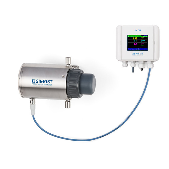
Instrument overview Instruction Manual ColorPlus 3 Instrument overview Overview of a measuring point Figure 1: Overview of a measuring point SICON control unit ColorPlus 3 Sample outlet Measuring cell (example: 100 mm path length) ... -
Page 12: Designation Of The Colorplus 3
Instruction Manual ColorPlus 3 Instrument overview Designation of the ColorPlus 3 The SICON control unit and ColorPlus 3 are each fitted with a rating plate: Figure 2: Rating plates on the instruments Manufacturer Country of origin ... -
Page 13: Scope Of Supply And Accessories
Instrument overview Instruction Manual ColorPlus 3 Scope of supply and accessories 2.3.1 Standard scope of supply for the ColorPlus 3 PCS. ART. NO. NAME VIEW VARIANT See the ColorPlus 3 website Layer 100/10 Layer 50/10 mm Nitrate: ... -
Page 14: Optional Accessories For The Colorplus 3
Instruction Manual ColorPlus 3 Instrument overview 2.3.2 Optional accessories for the ColorPlus 3 PCS. ART. NO. NAME VIEW VARIANT 118442 Profibus DP inter- For SICON (M) only faces print 118445 Modbus RTU inter- For SICON (M) only faces print 119796... -
Page 15: Technical Data For The Colorplus 3
Instrument overview Instruction Manual ColorPlus 3 Technical data for the ColorPlus 3 Absorbance measu- Values rement Measuring principle Absorption Measuring scope UV 100 mm 0 .. 1 to 0 .. 30 E/m UV 50 mm 0 .. 2 to 0 .. 60 E/m Nitrate 5/1.5... - Page 16 Instruction Manual ColorPlus 3 Instrument overview Measuring cell data Values Material PVC housing, stainless steel 1.4435 Window Quartz glass Plastic push-in connec- D = 8 mm / G ¼" thread tions Max. medium tempe- 0 .. 50 °C rature Max. medium pressure...
-
Page 17: General Safety Points
General safety points Instruction Manual ColorPlus 3 General safety points Dangers when properly used Damaged instrument or cabling. Touching damaged cables may lead to electrical shocks or death. The instrument may be operated only when the cables are undamaged. -
Page 18: Residual Risk
Penetration of moisture as well as condensation on the electrical components dur- ing servicing duty. If moisture enters the instrument, the ColorPlus 3 can be damaged. Work inside the instrument may be performed only in a dry room and at room tempera- CAUTION! ture. -
Page 19: Preventing Undesirable Online Access Attempts
Instruction Manual ColorPlus 3 Preventing undesirable online access attempts SIGRIST instruments are equipped with an integrated web user interface and Mod- bus TCP interface, thus offering state-of-the-art administration and control possibil- ities. However, if these are connected directly to the Internet, then any Internet us- er can in principle access your instrument and change the configuration. -
Page 20: Mounting
Mounting the ColorPlus 3 Note the following points when mounting the instrument: The ColorPlus 3 must be installed horizontally. The sample outlet (Y) must be positioned at the top so that the measuring cell can be well ventilated. ... -
Page 21: Mounting The Sicon (M)
Mounting Instruction Manual ColorPlus 3 Mounting the SICON (M) WORKSTEP ADDITIONAL INFO / IMAGES Open the shutters. Fasten the control unit to the wall using four screws (circles). 14501E/2... -
Page 22: Electrical Installation
Instruction Manual ColorPlus 3 Electrical installation Electrical installation Safety pointers for the electrical connection Connecting the service voltage. Improper connection of the service voltage can be potentially fatal. The system may also be damaged. Local regulations for electrical connection must be observed at all times. -
Page 23: Opening The Cover On The Sicon (M)
Electrical installation Instruction Manual ColorPlus 3 Opening the cover on the SICON (M) WORKSTEP ADDITIONAL INFO / IMAGES Open the shutters. Loosen the fastening screws on the cover. Open the cover. Fasten the cover with the cover clamp. To do this, remove the cover clamp from the park po- sition (X) and fasten the cover in position (Y). -
Page 24: Overview Of The Opened Sicon (M) Control Unit
Instruction Manual ColorPlus 3 Electrical installation Overview of the opened SICON (M) control unit Figure 3: Overview of SICON (M) Park position for cover clamp microSD card (card for log data) USB connection Ethernet connection ... -
Page 25: Connecting The Sicon (M)
Electrical installation Instruction Manual ColorPlus 3 Connecting the SICON (M) Life-threatening voltage inside the instrument. Connecting electrical lines can be extremely dangerous. Instrument parts may also be dam- aged. Local regulations for electrical installations must be observed at all times. -
Page 26: Connecting The Instrument Cable To The Colorplus 3
Instruction Manual ColorPlus 3 Electrical installation Connecting the instrument cable to the ColorPlus 3 A 4-pin connector of type M12 x 1 with A-coding is used. The connector assignment is as follows: Description Connector Wire color for device ca- Remarks... -
Page 27: Cable Cross-Sections Over Longer Distances
Electrical installation Instruction Manual ColorPlus 3 5.5.1 Cable cross-sections over longer distances For connections longer than the standard cable length, an optional connection box must be connected between the photometer and control unit. The maximum distance between the control unit and photometer depends on the cable cross-section used and the available power supply (see table below). -
Page 28: Connecting The Connection Box
Instruction Manual ColorPlus 3 Electrical installation Connecting the connection box The terminals in the connection box are assigned as follows: CONNECTION FOR PHOTOMETER CONNECTION FOR CONTROL UNIT Terminal Cable Terminal Function Blue White Blue Orange Brown Orange 24 V Dark gray... -
Page 29: Connecting The Optional Flow Meter
Electrical installation Instruction Manual ColorPlus 3 Connecting the optional flow meter The following procedure describes how to install the flow meter on the ColorPlus 3: WORKSTEP ADDITIONAL INFO / IMAGES Interrupt the service voltage to the photome- ter. Unscrew the cover on the ColorPlus 3. -
Page 30: Connecting The Optional 24 Vdc Power Supply
Instruction Manual ColorPlus 3 Electrical installation Connecting the optional 24 VDC power supply Life-threatening voltage due to accidentally released voltage-carrying wires. The wires of the supply connection must be secured with cable ties so that if one wire accidentally becomes loose no other parts can be charged with voltage. -
Page 31: Connecting The Field Bus Interfaces (Optional)
Electrical installation Instruction Manual ColorPlus 3 Connecting the field bus interfaces (optional) Information on commissioning the field bus interfaces can be found in the Reference Handbook. 5.9.1 Overview of Profibus DP and Modbus RTU Figure 7: Overview of the Profibus DP and Modbus RTU modules ... -
Page 32: Overview Of Profinet Io
Instruction Manual ColorPlus 3 Electrical installation 5.9.3 Overview of Profinet IO To connect to the Profinet IO, the Profinet IO module must be integrated in the SICON (M). The module has an internal switch and provides two Ethernet ports. -
Page 33: Overview Of Hart
Electrical installation Instruction Manual ColorPlus 3 5.9.4 Overview of HART Information on commissioning the field bus interfaces can be found in the Reference Handbook. Figure9: Overview of the HART module Field bus interface (connection HART terminals print) for HART. Serves as interface to HART. -
Page 34: Connecting The Analog Modules (Optional)
Instruction Manual ColorPlus 3 Electrical installation 5.10 Connecting the analog modules (optional) 5.10.1 Overview of 4-way current output The configuration of the current outputs is described in the Section 8.2. Figure 10: Overview of the 4-way current output module ... -
Page 35: Overview Of The 4-Way Current Input
Electrical installation Instruction Manual ColorPlus 3 5.10.3 Overview of the 4-way current input The configuration of the current inputs is described in the Reference Handbook. Figure 11: Overview of the 4-way current input module 4-way current input Terminals 5.10.4 Connecting the 4-way current input... -
Page 36: Commissioning
Instruction Manual ColorPlus 3 Commissioning Commissioning The initial start-up of the web user interface via the Ethernet interface is described in the Reference Manual. If malfunctions occur, consult the Section 10. Proceed with the initial start-up in accordance with the following table:... -
Page 37: Operation
Operation Instruction Manual ColorPlus 3 Operation Operation basics In this document we describe the practical examples only for the first steps of the menu con- figuration. All other setting options are described in the Reference Handbook. Operation us- ing the web user interface is described in detail in the Reference Handbook. -
Page 38: Control Elements In Measuring Mode
Instruction Manual ColorPlus 3 Operation Control elements in measuring mode Figure 12: Control elements in measuring mode Menu button Valu button Calls up the menu structure. Sec- Numerical representation of the meas- tion 7.3 uring values. Section 7.4 ... -
Page 39: Info Button
Operation Instruction Manual ColorPlus 3 Info button When you press the Info button, a general overview of the instrument settings appears. 7.5.1 Page 1, Info button Figure 13: Info button, screen 1 Information about the available Status of the inputs ... -
Page 40: Info Button
Instruction Manual ColorPlus 3 Operation 7.5.2 Page 2, Info button Figure 14: Info screen, page 2 Contact information Display of up to 5 pending fault mes- sages 14501E/2... -
Page 41: Diag Button
Operation Instruction Manual ColorPlus 3 Diag button When you press the Diag button, a diagram appears which graphically shows the measuring values over a certain period of time. Figure 15: Graphic representation of the measuring values Graphic representation of the... -
Page 42: Functions Of The Log Screen (Log Button)
Instruction Manual ColorPlus 3 Operation Functions of the log screen (Log button) The screen logger works independently of the data logger, which is set in the Logger menu and writes to the microSD card. The screen logger records the data of the last 32 days in one-minute intervals. The data can be called up from the Log menu. -
Page 43: Displays In Measuring Mode
Operation Instruction Manual ColorPlus 3 Displays in measuring mode Figure 17: Displays in measuring mode Measuring value(s) Status line For values which are greater than In measuring mode, the status line is the maximum measuring range, no green and shows the date and time. -
Page 44: Lock / Unlock The Touch Screen
Instruction Manual ColorPlus 3 Operation Lock / unlock the touch screen MANIPULATION Press the lock icon top left. Within one second press the key bottom at the outside right. Depending on the initial state, the lock icon changes as follows:... -
Page 45: Switching To Service Mode
Operation Instruction Manual ColorPlus 3 7.10 Switching to service mode The system is configured in service mode. The measuring procedure is interrupted and the main menus appear on the display. Service mode is accessed as follows: MANIPULATION ADDITIONAL INFO / IMAGES Press the Menu button. -
Page 46: Control Components In Service Mode
Instruction Manual ColorPlus 3 Operation 7.11 Control components in service mode 7.11.1 Input elements in service mode Figure 18: Input elements in service mode Path specification Page number / total number of pages Main menus... -
Page 47: Numerical Entry
Operation Instruction Manual ColorPlus 3 7.11.2 Numerical entry The following screen is for entering numbers and data: Figure 19: Numerical entry Parameter name Entered values Prefix: For entering very large or Numerical entry very small values. This can be done as follows: 1. -
Page 48: Single Selection Of Functions
Instruction Manual ColorPlus 3 Operation 7.11.3 Single selection of functions The single selection is identifiable by the ESC button in the lower right corner. The currently selected function is green. Use the Up/Down arrows to navigate the options in long lists. -
Page 49: Settings
Settings Instruction Manual ColorPlus 3 Settings Setting the operating language MANIPULATION ADDITIONAL INFO / IMAGES Press the Menu button. Enter the access code and confirm with OK. Factory setting is 0. Press the Configuration button to access lan- If the desired menu does not guage selection. -
Page 50: Setting The Current Outputs
Instruction Manual ColorPlus 3 Settings Setting the current outputs MANIPULATION ADDITIONAL INFO / IMAGES Press the Menu button. Enter the access code and confirm with OK. Factory setting is 0. Press the Curr. outputs button. If the desired menu does not appear, press the arrow at the bot- tom right. -
Page 51: Setting The Limits
Settings Instruction Manual ColorPlus 3 Setting the limits The limits have to be configured accordingly so that they are not only displayed, but that the outputs are also switched. Section 8.4 MANIPULATION ADDITIONAL INFO / IMAGES Press the Menu button. -
Page 52: Upper And Lower Threshold Value Of A Limit
Instruction Manual ColorPlus 3 Settings 8.3.1 Upper and lower threshold value of a limit A maximum of eight limits with upper and lower threshold can be programmed. If the operating mode is set to Exceeded (Figure 22), then while the upper threshold is... -
Page 53: Setting The Outputs
Settings Instruction Manual ColorPlus 3 Setting the outputs MANIPULATION ADDITIONAL INFO / IMAGES Press the Menu button. Enter the access code and confirm with OK. Factory setting is 0. Press the Inp./outputs button. If the desired menu does not appear, press the arrow at the bot- tom right. -
Page 54: Activating The Optional Flow Meter
Instruction Manual ColorPlus 3 Settings Activating the optional flow meter MANIPULATION ADDITIONAL INFO / IMAGES Press the Menu button. Enter the access code and confirm with OK. Factory setting is 0. Press the Ana. channels button. If the desired menu does not appear, press the arrow at the bot- tom right. -
Page 55: Setting The Date And Time
Settings Instruction Manual ColorPlus 3 Setting the date and time MANIPULATION ADDITIONAL INFO / IMAGES Press the Menu button. Enter the access code and confirm with OK. Factory setting is 0. Press the Configuration button. If the desired menu does not appear, press the arrow bottom right. -
Page 56: Setting Or Changing The Access Code
Enter the access code and confirm with OK. Press the Meas button. The instrument is in measuring mode again. A forgotten access code can be cleared only by a SIGRIST service engineer. Enter your personal access code here: 14501E/2... -
Page 57: Backup Configured Data
Settings Instruction Manual ColorPlus 3 Backup configured data These measures can be of use to the service engineers for service purposes. MANIPULATION ADDITIONAL INFO / IMAGES Press the Menu button. Enter the access code and confirm with OK. Factory setting is 0. -
Page 58: Servicing
If servicing duties are not carried out according to the servicing schedule or non-original SIGRIST spare parts are used, this can lead to damage to the instrument or measuring errors. CAUTION! In this case, SIGRIST-PHOTOMETER AG accepts no warranty claims made by the customer and is not responsible for any subsequent costs. -
Page 59: Servicing Schedule
Servicing Instruction Manual ColorPlus 3 Servicing schedule WHEN WHAT PURPOSE Annually or as Operator Clean the measuring cell. Obligatory measure for main- needed taining measuring accuracy. In- Section 9.2 terval dependent on measuring medium. Annually or in Operator Replace the desiccant. -
Page 60: Cleaning The Measuring Cell
Do not use any reflective objects when cleaning the measuring cell. Loosen the screw cap and remove it from the ColorPlus 3 together with the cap. Pull out the sample distributor (A) and outlet pipe (B) and clean with a bottle brush. - Page 61 Servicing Instruction Manual ColorPlus 3 WORKSTEP ADDITIONAL INFO / IMAGES Clean the four measuring cell windows (ar- rows) with ethanol. Do not use abrasive cleaning agents. Remove the remaining part of the measuring cell. Grease the gaskets on the sample distributor and outlet pipe (position X).
-
Page 62: Replacing The Desiccant
Instruction Manual ColorPlus 3 Servicing Replacing the desiccant The following procedure describes how to replace the desiccant in the ColorPlus 3: WORKSTEP ADDITIONAL INFO / IMAGES Unscrew the cover on the ColorPlus 3. Replace the old desiccant bag with a new one. -
Page 63: Recalibrating The Photometer
Servicing Instruction Manual ColorPlus 3 Recalibrating the photometer Recalibrating the photometer can result in deviations from the previous measuring value as the instrument is newly reset to a reference value (e.g. distilled water). WORKSTEP ADDITIONAL INFO / IMAGES Fill the measuring cell with a zero medium (dis- There must be no air bubbles tilled water). -
Page 64: Carrying Out The Sensor Check
Instruction Manual ColorPlus 3 Servicing Carrying out the sensor check The sensor check is an internal functional check of the photometer that is carried out auto- matically once a week as standard. This period can be set freely or deactivated completely (Menu\Spec. -
Page 65: Replacing The Filter Cartridge On The Filter Unit
Servicing Instruction Manual ColorPlus 3 Replacing the filter cartridge on the filter unit Only carry out this servicing duty on instruments with an optional filter unit. Figure 23: Filter unit Filter unit Union nuts Filter housing with fine filter: Filter housing with coarse filter 20 µm... -
Page 66: Changing The Battery In The Sicon (M)
Instruction Manual ColorPlus 3 Servicing Changing the battery in the SICON (M) Life-threatening voltage inside the instrument. Connecting electrical lines can be extremely dangerous. Instrument parts may also be dam- aged. Local regulations for electrical installations must be observed at all times. -
Page 67: Troubleshooting
Troubleshooting Instruction Manual ColorPlus 3 10 Troubleshooting 10.1 Pinpointing faults DETECTABLE FAULT MEASURE No reading Check whether the supply voltage is connected. Check whether the mains plug is connected. Check whether the instrument is switched on. ... - Page 68 Instruction Manual ColorPlus 3 Troubleshooting The following warning messages can be displayed: WARNING DESCRIPTION POSSIBLE CAUSES MESSAGE V IN The input voltage is outside The service voltage is faulty. the permitted range (20 .. 26.5 VDC). ADJUST FAULT Recalibration could not be The instrument is soiled.
-
Page 69: Fault Messages And Effect On Operation
Troubleshooting Instruction Manual ColorPlus 3 WARNING DESCRIPTION POSSIBLE CAUSES MESSAGE SERVICE Shows when service work is Service work is due. due. VERS.SD CARD The data on the microSD card Update was performed incor- does not match the current rectly. - Page 70 Instruction Manual ColorPlus 3 Troubleshooting FAULT MESSAGE DESCRIPTION POSSIBLE CAUSES MEASUR. FAULT Measuring value acquisition is Bubbles in the water. faulty. External light in the vicinity of the measuring point (e.g. transparent hoses). Defect in the electronic system.
-
Page 71: Prioritized Fault Messages And Their Effect On Operation
Troubleshooting Instruction Manual ColorPlus 3 10.1.3 Prioritized fault messages and their effect on operation When there is a prioritized fault, the cause of the malfunction is serious. CAUTION! PRIO (PRIORITIZED FAULT) If a prioritized fault occurs during operation, it has the following effects: ... -
Page 72: Customer Service Information
A current list of all SIGRIST country representatives is available online at www.photometer.com. Please have the following information ready when you contact a SIGRIST service point or customer service: ... -
Page 73: Decommissioning/Storage
Decommissioning/Storage Instruction Manual ColorPlus 3 12 Decommissioning/Storage 12.1 Decommissioning the photometer The aim of decommissioning is to prepare the individual components of the system properly for storage. WORKSTEP ADDITIONAL INFO / IMAGES Interrupt the service voltage to the instrument. Stop the sample flow and let the measuring cell run empty. -
Page 74: Packaging / Transport / Returning
The original packaging materials should be used for packaging the ColorPlus 3 if possible. If the original packaging is no longer available, note the following information: ... -
Page 75: Disposal
Disposal Instruction Manual ColorPlus 3 14 Disposal Disposal of the system and its peripheral devices is to be carried out in compliance with re- gional statutory regulations. The system has no environmentally damaging sources of radiation. The materials listed be-... -
Page 76: Spare Parts List
Instruction Manual ColorPlus 3 Spare parts list 15 Spare parts list The parts mentioned in this documentation and their article numbers are listed in the follow- ing table: NO. ARTICLE DESIGNATION REMARQUES 111391 Desiccant bag, 30 g 118265 O-ring FPM 88 x 2 120958 O-ring EPDM 50.39 x 3.53... - Page 77 Spare parts list Instruction Manual ColorPlus 3 This pa ge is inte ntionally bla nk 14501E/2...
-
Page 78: Index
Instruction Manual ColorPlus 3 Index 16 Index Flow meter ............ 29, 54 4-way current input ..........35 4-way current output ........... 34 Glossary ..............7 Access code, set ........... 56 HART..............33 Analog modules ........... 34 Article numbers ............ 76 Improper use ............ - Page 79 Index Instruction Manual ColorPlus 3 Replacing the desiccant ........59, 62 Replacing the water filter ....... 59, 65 Target group of the document ......7 Residual risk ............18 Technical data ............. 15 Terms, glossary ............7 Touchscreen ............37 Safety symbols .............
- Page 80 SIGRIST-PHOTOMETER AG Tel. +41 41 624 54 54 Hofurlistrasse 1 +41 41 624 54 55 CH-6373 Ennetbürgen info@photometer.com Switzerland www.photometer.com...
Need help?
Do you have a question about the ColorPlus 3 and is the answer not in the manual?
Questions and answers