Table of Contents
Advertisement
Quick Links
INSTRUCTION MANUAL
Fluorescence Measuring
Document number: 10241E
OilGuard Ex M
SIGRIST
Instrument
(Valid from software Version 1.4)
SIGRIST-PHOTOMETER AG
Hofurlistrasse 1
CH-6373 Ennetbürgen
Switzerland
Version: 2
Phone:
+41 (0)41 624 54 54
Fax:
+41 (0)41 624 54 55
E-mail:
info@photometer.com
Internet: www.photometer.com
Valid from: 1.8.2007
Advertisement
Table of Contents

Related Manuals for SIGRIST OilGuard Ex M


Summary of Contents for SIGRIST OilGuard Ex M
- Page 1 INSTRUCTION MANUAL OilGuard Ex M SIGRIST Fluorescence Measuring Instrument (Valid from software Version 1.4) SIGRIST-PHOTOMETER AG Phone: +41 (0)41 624 54 54 Hofurlistrasse 1 Fax: +41 (0)41 624 54 55 CH-6373 Ennetbürgen E-mail: info@photometer.com Switzerland Internet: www.photometer.com Document number: 10241E Version: 2 Valid from: 1.8.2007...
- Page 2 © SIGRIST-PHOTOMETER AG, Subject to change without notice 08/07...
-
Page 3: Table Of Contents
Instruction Manual OilGuard Ex M Contents 1 Instrument description .................1 1.1 Overview of the measuring point ............1 1.2 Scope of delivery and accessories...........2 1.3 Intended purpose and conformity............2 1.4 Product identification ..............3 1.5 Technical data ................4 2 Safety regulations ................6 2.1 Symbols used on the photometer............6... - Page 4 Instruction Manual OilGuard Ex M 7 Decommissioning & storage ............... 47 8 Packaging & transport ............... 48 9 Disposal................... 49 10 Spare parts ..................50 11 Appendix ..................51 12 Index....................53 10241E/2...
- Page 5 Instruction Manual OilGuard Ex M Foreword This Instruction Manual describes the basic functions for operating the OilGuard Ex M. It is intended for all persons responsible for the operation of the instrument. Operate the instrument only after you are familiar with the Instruction Manual.
- Page 6 Instruction Manual OilGuard Ex M 10241E/2...
-
Page 7: Instrument Description
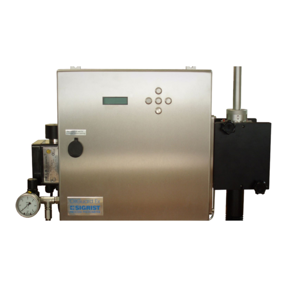
Instruction Manual OilGuard Ex M 1 Instrument description Overview of the measuring point Overview of a Ex zone Non-Ex zone measuring point Figure 1: Overall view OilGuard Ex M Pos. Name Positions in Figure 1 Display Keyboard Inlet tube OilGuard data logger... -
Page 8: Scope Of Delivery And Accessories
Instruction Manual OilGuard Ex M Scope of delivery and accessories Standard scope Pcs. Name Variants/remarks of delivery Ex cabinet with photometer and integrated operating unit Instruction Manual Reference Handbook German, English Brief Instructions Technical Documentation For Ex control unit Measuring cell... -
Page 9: Product Identification
Instruction Manual OilGuard Ex M The photometer is TÜV certified for Ex safety (each instrument is approved individually). Current technological principles were complied with during design and production. They correspond to the usual guidelines concerning duty to take due care and safety. -
Page 10: Technical Data
Read Instruction Manual! Disposal information → Section 9 Figure 3: Identification plate OilGuard Ex M You can also find out the serial number of the photometer in the * SYSTEM * menu (→ Reference Handbook). Technical data Measuring Fluorescence measurement... - Page 11 Instruction Manual OilGuard Ex M Photometer Voltage supply See Identification plate (→ Figure 3) Current supply 1 x 0/4..20 mA (max. 600 Ω, max. 24 V) with galvanic isolation, max. 50 V relative to earthing Power P = 65 W / S = 150 VA...
-
Page 12: Safety Regulations
Instruction Manual OilGuard Ex M 2 Safety regulations Symbols used on the photometer The symbols used on the instrument refer to the following safety measures and precautions: DANGER (BLACK ON YELLOW) Warning about a general source of danger. This symbol designates areas or manipulations for which special safety rules must be adhered to. -
Page 13: Installation & Commissioning
Instruction Manual OilGuard Ex M 3 Installation & commissioning Installation of the Photometer The following procedure has proven to be reliable when installing a measuring point: Action Remove the photometer from the packaging. Attach the photometer horizontally to the intended location. -
Page 14: Installation Of The Free-Fall Measuring Cell
Instruction Manual OilGuard Ex M The line between bilge separator and drain line must be as short as possible! It must be ensured that the sample arrives at the photometer within 15 s. The discharge must be pressureless (do not use siphon or similar components) 3.1.2 Installation of the free-fall measuring cell... -
Page 15: Installation Of Cooling Element
Instruction Manual OilGuard Ex M Action Fit the lock nut (C) over the inlet tube and turn clockwise to fix in place (bayonet connector). Connect the inlet tube to the sample supply and the discharge to the sample return line. -
Page 16: Electrical Connections
Instruction Manual OilGuard Ex M Action Connect the cooling water to the feed and drain. ∅ inner hose = 10 mm The water flow rate must be at least 1 l/min! Max. pressure = 500 kPa (5 bar) A= feed below B= drain above Open the cooling water supply. -
Page 17: Connecting The Mains Voltage To The Ex Control Unit
Instruction Manual OilGuard Ex M 3.2.1 Connecting the mains voltage to the Ex control unit Action Remarks Undo the four screws (circled) and Connecting the remove the cover from the Ex mains cable control unit. Remove the cable conduit glands and then insert the mains cable into the Ex control unit. -
Page 18: Opening The Sealed Front Door
Instruction Manual OilGuard Ex M 3.2.2 Opening the sealed front door To open the front door, it is necessary to break the seal. The seal is evidence that the instrument has not be altered (requirement of IMO MEPC-107[49]). The seal may be renewed only by authorized persons (service engineers). The operator may remove the seal only in exceptional cases (e.g. -
Page 19: Principle Of The Cable Terminals
Figure 6: Large terminals 3.2.4 Adapting to lower mains voltage Operation with The OilGuard Ex M standard version is designed for 230 V mains voltage. For lower supply voltages than 230 V, the photometer is equipped with a lower mains voltage matching transformer. -
Page 20: Connecting The Data Lines
Instruction Manual OilGuard Ex M Action Remarks Place the wire coming from the fine-wire fuse (A) onto the appropriate terminal (100 V, 115 V or 130 V). By default the wire is on the 115 V terminal. On the terminal strip you can fine tune with 110 V, 115 V or 130 V. -
Page 21: Connecting The Oilguard Data Logger
Instruction Manual OilGuard Ex M Establish the electrical connections in the following sequence: Terminals Meaning Remarks 4 - 5 - 6 Relay output 1 Connecting the → Section 4.6 photometer → Reference Handbook 7 - 8 - 9 Relay output 2... -
Page 22: Installing The Software For Oilguard Data Logger
Instruction Manual OilGuard Ex M The following terminals are used for connecting the data logger: Terminals in the Terminals in the OilGuard data Remarks Terminal assignment photometer logger (1) for data logger connection → Section 3.2.5, → Figure 9 + 24 V Pos. -
Page 23: Start Up The Oilguard Data Logger With The Software
Instruction Manual OilGuard Ex M 3.2.8 Start up the OilGuard data logger with the software Once you have launched the software (HOBOware) of the data logger, the following startup screen appears (→ Figure 11): Pos. Name Start up data logger... - Page 24 Instruction Manual OilGuard Ex M Action Remarks Based on Section 5.6, check whether the data logger has correctly launched. Figure 12 : Check data logger data (HOBOware) Positions in Pos. Name Figure 12 Instrument name and serial number Name of input 1 of the data logger...
-
Page 25: Check Connection Between Pc And Oilguard Data Logger
Instruction Manual OilGuard Ex M Check connection between PC and OilGuard data logger The connection between the OilGuard data logger and the PC can be checked in the following way: Action Remarks Start up the HOBOware software and read out Check connection the "Logger state"... -
Page 26: Initial Startup
Instruction Manual OilGuard Ex M Initial startup For the initial startup, proceed according to the following table. In the event of faults, please refer to Section 6. Action Remarks Make sure that the photometer is → Section 3.1 and 3.2 First commissioning correctly mounted and connected. -
Page 27: Operation
Instruction Manual OilGuard Ex M 4 Operation Operating keyboard and display Figure 14: Operating elements and display. Pos. Name Positions in Figure 14 Reading Unit Measuring range Left button Up button Right button Enter button Down button Button functions Change between menu lines... -
Page 28: Normal Operation
Instruction Manual OilGuard Ex M Normal operation After switching on the instrument, it is in normal operation. The current reading / measuring range is display continuously. The following displays may also appear (examples): The display… Means... You should then... ***** ppm 1 …that the reading is... -
Page 29: Function Of The Oilguard Data Logger In Normal Operation
Instruction Manual OilGuard Ex M Function of the OilGuard data logger in normal operation The OilGuard data logger saves the two events "Alarm status" and "Separator on" as follows: LED display Possible event On the "Alarm status" the warm-up phase... -
Page 30: Setting The Language
Instruction Manual OilGuard Ex M Setting the language You can set the language of the menus and messages to your region as follows: Action Display (example) Remarks Activate service * RECALIBR. Section 4.4 Language mode * CONFIGURATION* > Language <... - Page 31 Instruction Manual OilGuard Ex M Abbrev. Meaning Setting Relay 2 Configurable Limit exceeded Alarm (fault has occurred) Changeable Instrument in service mode Adjustment in progress Relay inverted fixed Action Display (example) Remarks Activate service Section 4.4 * RECALIBRATION* Programming relay 2...
-
Page 32: Setting The Access Code
< the field so that it is not change position forgotten! Confirm selection. > Access code < 24.0 Unit in normal operation. (simultaneously) New access code: A forgotten access code can be cleared only by a SIGRIST service engineer! 10241E/2... -
Page 33: Other Options
This documentation describes only the options that are necessary for the initial startup and normal operation of the instrument. Please refer to the Reference Handbook supplied with your measuring instrument to find out about other options for your SIGRIST Photometer OilGuard Ex M. 10241E/2... -
Page 34: Maintenance
Instruction Manual OilGuard Ex M 5 Maintenance The front door may be opened only after the voltage supply has been disconnected and after waiting five minutes so that the light source can cool down sufficiently (EXPLOSION HAZARD). The seal on the front door may be renewed only by authorized persons (service engineers). -
Page 35: Clean Free-Fall Measuring Cell
Instruction Manual OilGuard Ex M Pos. Name Design of the photometer Light source Optics area Control unit OilGuard data logger with connecting cable Electronics area Pressure regulator with gauge Ex control unit Figure 15: Design of the photometer Clean free-fall measuring cell Depending on the application, deposits can form on different parts of the measuring cell. - Page 36 Instruction Manual OilGuard Ex M Action Remove the lock nut by turning it counter-clockwise (bayonet connector) and then pull out the inlet tube. Pull out the protective tube (A). Remove the protective windows (1, 2) from the pins and clean them outside the measuring cell housing.
- Page 37 Instruction Manual OilGuard Ex M Action Check inlet tube and protective tube for deposits and remove if necessary. If an inlet tube is defective, it must be replaced (→ Section 6.2). Do not remove deposits with a knife or similar objects (use a soft material).
-
Page 38: Replace Light Source
Instruction Manual OilGuard Ex M Replace light source Action Disconnect the voltage supply to the Replace light source photometer. The front door may be opened only after the voltage supply has been disconnected and after waiting five minutes so that the light source can cool down sufficiently (EXPLOSION HAZARD). - Page 39 Instruction Manual OilGuard Ex M Action Position the new light source holder so that the light source faces front (arrow). When inserting the light source holder, pay attention to the pins. The pins must be engaged. Fasten the light source holder by tightening the two screws.
- Page 40 Instruction Manual OilGuard Ex M Action Remove the quartz glass from the light source cover and clean it. Re-insert the glass. Mount the light source cover and fasten it with the two screws. Close the front door using the special wrench.
-
Page 41: Replace Fan
Instruction Manual OilGuard Ex M Action Attach the supplied seal to the front door (→ Section 0) Make a note of the seal number in the maintenance protocol. Replace fan Action Disconnect the voltage supply to the Replace fan photometer. -
Page 42: Recalibrating The Photometer
After the photometer has been recalibrated, deviations from the previous reading may result, since the instrument has to be re-set to a fixed reference value. Recalibration is performed with the SIGRIST control unit with built-in solid Recalibration with control unit particle reference. - Page 43 Instruction Manual OilGuard Ex M Fluorescence glass Arrester screws Serial number Adjust value Figure 16: SIGRIST control unit Action Interrupt the sample supply and remove Install control unit the feed house. Loosen the two arrester screws and remove the cover from the measuring cell.
- Page 44 Instruction Manual OilGuard Ex M Action Remove the lock nut by turning it counter- clockwise (bayonet connector) and then pull out the inlet tube. Remove the protective tube (A). Mount the control unit and fix in place with the two arrester nuts.
- Page 45 Instruction Manual OilGuard Ex M Action Display (example) Remarks > Adju. < Retain Adju. > Retain < Adju. > Adapt < Adju. running ... Wait until the - Measure – Display of "raw“ check X.XXX FLU photometer has values without reading determined the adjustments.
-
Page 46: Check The Oilguard Data Logger For Functionality
Instruction Manual OilGuard Ex M Check the OilGuard data logger for functionality Pos. Name Connection terminals Backup battery Status indicator Operation indicator USB connection Figure 17: OilGuard data logger Action Remarks Check whether the operation indicator (4) flashes → Figure 17... -
Page 47: Reading Out The Oilguard Data Logger And Saving The Data
Instruction Manual OilGuard Ex M Reading out the OilGuard data logger and saving the data The data storage capacity of the OilGuard data logger is limited. To ensure seamless logging without gaps, the data must be periodically saved to a PC system. -
Page 48: Troubleshooting
Instruction Manual OilGuard Ex M 6 Troubleshooting Identifying the cause of a fault Use the table below to identify the cause of a fault systematically. If the listed measures do not result in the desired results, please consult with customer service (→... -
Page 49: Replace Inlet Tube
Instruction Manual OilGuard Ex M Replace inlet tube Action Remove the sample feed and return line Replace inlet tube and let the measuring cell run empty. Remove the lock nut by turning it counter-clockwise (bayonet connector) and then pull out the inlet tube. -
Page 50: Fault Reports
Instruction Manual OilGuard Ex M Fault reports If a fault occurs during operation, **** Fault **** appears in the display with a fault report, which can help in determining the cause of the fault. Message Meaning Possible causes Connection The control unit cannot - Interrupted connection between lost…... -
Page 51: Customer Service Information
Should you do not find the answer to your question, please contact a service agent in your country or region. If this is not known, the SIGRIST- PHOTOMETER AG customer service in Switzerland would be glad to provide you with a contact address. - Page 52 Instruction Manual OilGuard Ex M In the event that you have problems with the reading, please also have the Instrument data following information ready, which you can find in the information part of the menu structure: Name Option Value Remarks...
-
Page 53: Decommissioning & Storage
Instruction Manual OilGuard Ex M 7 Decommissioning & storage The aim of decommissioning is to prepare the photometer properly for storage and to conserve it during storage. Action Disconnect the voltage supply to the photometer and remove all electrical Decommissioning connections. -
Page 54: Packaging & Transport
Instruction Manual OilGuard Ex M 8 Packaging & transport The original packaging materials should be used for packaging the photometer and its peripheral components if possible. If the original packaging is no longer available, note the following information: Before packaging the photometer, close the openings of the photometer with adhesive tape or plugs so that no packaging materials can enter the instrument. -
Page 55: Disposal
Instruction Manual OilGuard Ex M 9 Disposal According to European Directive RL 2002/95/EC (RoHS), this product falls into category 9 “Monitoring and control instruments”. Disposal of the photometer and its peripheral devices is to be carried out in compliance with regional legal regulations! The photometer has no environmentally damaging sources of radiation. -
Page 56: Spare Parts
Instruction Manual OilGuard Ex M 10 Spare parts The parts mentioned in this documentation and their article numbers are listed in the table below: Art. no. Article name 116981 Light source, adjusted, with seal 116982 Fan with plug & seal... -
Page 57: Appendix
Instruction Manual OilGuard Ex M 11 Appendix Serial number: Maintenance protocol Adj. nom. value: First commissioning: Remarks: Adjustment Seal Maintenance work Date Initials value number 10241E/2... - Page 58 Instruction Manual OilGuard Ex M Adjustment Seal Maintenance work Date Initials value number 10241E/2...
-
Page 59: Index
Instruction Manual OilGuard Ex M 12 Index access code, setting ....26 guidelines ........3 accessories ....... 2 article numbers ....... 50 HOBOware ....iii, 16, 17 hoses........7 bilge separator ......8 Brief Instructions ....... iii identification plate......4 bus coupler....... 2 IMO........3, 14 inlet tube........1... - Page 60 Instruction Manual OilGuard Ex M proper use.........2 standards........2 protect, settings ...... 26 startup, initial ......20 protection index ......6 storage ........47 suspended particle reference ..36 symbols........6 recalibration ...... 36, 39 system F-350 ......iii Reference Handbook ....iii SystemFault ......
Need help?
Do you have a question about the OilGuard Ex M and is the answer not in the manual?
Questions and answers