Table of Contents
Advertisement
Quick Links
INSTRUCTION MANUAL
StackGuard 2 SYSTEM
Dust Emissions Measuring System
Document No.: 10198E
SIGRIST
SIGRIST-PHOTOMETER AG
Hofurlistrasse 1
CH-6373 Ennetbürgen
Switzerland
Version: 3
Phone:
041/624 54 54
Fax:
041/624 54 55
E-mail:
info@photometer.com
Internet:
www.photometer.com
Valid from: Software V1.3
Advertisement
Table of Contents

Subscribe to Our Youtube Channel
Related Manuals for SIGRIST StackGuard 2


Summary of Contents for SIGRIST StackGuard 2
- Page 1 INSTRUCTION MANUAL StackGuard 2 SYSTEM SIGRIST Dust Emissions Measuring System SIGRIST-PHOTOMETER AG Phone: 041/624 54 54 Hofurlistrasse 1 Fax: 041/624 54 55 CH-6373 Ennetbürgen E-mail: info@photometer.com Switzerland Internet: www.photometer.com Document No.: 10198E Version: 3 Valid from: Software V1.3...
- Page 2 © SIGRIST-PHOTOMETER AG, technical details subject to change 08/2005...
-
Page 3: Table Of Contents
Instruction Manual StackGuard 2 System Contents 1 Equipment Description ................1 1.1 Overall view of the measuring system ..........1 1.2 Scope of supply and accessories............2 1.2.1 Ring pipe ..................2 1.2.2 Special accessories..............2 1.3 Intended use and confor mity ..............3 1.4 Product marking ................... - Page 4 Instruction Manual StackGuard 2 System 9 Disposal.....................47 10 Spare Parts ....................48 11 Appendix ....................48 11.1 Service log ...................49 11.2 Fold-out orientation assistance for the measuring system ....53 12 Index ......................55 10198E/3...
- Page 5 Instruction Manual StackGuard 2 System Foreword This Instruction Manual describes the basic functions for operating the StackGuard. It is addressed to all persons who are responsible for operation of the instrument. Operate the instrument only after having familiarized yourself with the contents of this Instruction Manual.
-
Page 7: Equipment Description
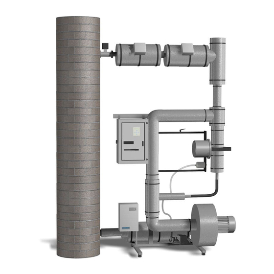
Instruction Manual StackGuard 2 System 1 Equipment Description Overall view of the measuring system Standard version of the ring pipe Shut-off valve in Supply pipe with heater sampling pipe Off gas duct Mixing section Sampletaking Sample divider with sampling Control unit... -
Page 8: Scope Of Supply And Accessories
You will find a list of all components used in your installation in the Specification Sheet attached to this Instruction Manual. 1.2.2 Special accessories Various special accessories are available for the StackGuard 2 system. Information on the special accessories supplied is provided in the Specification Sheet (see above). -
Page 9: Intended Use And Conformity
Instruction Manual StackGuard 2 System Intended use and conformity Use of the photometer for purposes other than those for which it was designed can produce incorrect measuring results, possibly with process- related consequential damage or even damage to the photometer itself! -
Page 10: Product Marking
Instruction Manual StackGuard 2 System Product marking Position of the rating plate on the photometer Figure 2 Location of the Stackguard rating plate The photometer’s rating plate carries the following informtion: Manufacturer data Country of manufacture Photometer designation Serial No. - Page 11 Instruction Manual StackGuard 2 System Rating plate on the control unit Figure 4 Location of the rating plate on SIGAR2 The SIGAR2 rating plate carries the following information: Manufacturer data Country of manufacture Control unit designation Serial No. Date of manufacture...
-
Page 12: Technical Data
Instruction Manual StackGuard 2 System Technical data Measurement data Measuring principle scattered light measurement Scatter angle 20° Measuring span 0 .. 0.050 PLA to 0 .. 100 PLA 0.0002PLA Resolution Reproducibility 2% (referred to full scale) 0.5% (referred to full scale) Repeatability ... - Page 13 Instruction Manual StackGuard 2 System Photometer No. of measuring ranges Weight about 8.4 kg Enclosure stainless steel, anodized aluminium Protection degree IP65 Flow cell Material stainless steel 1.4301 Window material borosilicate, B270 Seals Medium pressure max. 3000 Pa (=30 mbar) against ambient pressure at...
-
Page 14: Safety Rules
Instruction Manual StackGuard 2 System 2 Safety Rules Safety symbols used The symbols used on the instrument draw attention to the following safety measures or precautions: DANGER (BLACK ON YELLOW) Danger of a general hazard. This symbol marks areas or actions to which special safety rules apply. In... -
Page 15: Laser Safety Information
Caution – whenever operating or adjustment devices other than those specified by Sigrist are used or different procedures are carried out, exposure to dangerous radiation may result. 2.2.1 Laser data... -
Page 16: What To Do In An Emergency
Instruction Manual StackGuard 2 System What to do in an emergency In an emergency, the main switch can be used to cut off power to the entire installation. But this does NOT switch off the user’s signalling and control cables or the standby power supply for controlling the valves, provided this is... -
Page 17: Installation/Start-Up
Instruction Manual StackGuard 2 System 3 Installation/Start-up Placement The StackGuard 2 system must be installed at a weather-protected location on a flat surface with sufficient load-bearing capacity. Electrical connections 3.2.1 Instrument connections Installation and initial start-up are carried out by an installation technician from the SIGRIST country representative. - Page 18 Instruction Manual StackGuard 2 System Action Remarks Remove protective cover (A) of the control unit. Access to relay outputs and measured data outputs Loosen fastening screws (B) and swing down the hinged frame (C). Connection of the measured data outputs can be done without swinging down the hinged frame (C).
- Page 19 Instruction Manual StackGuard 2 System Terminals on Used for Remarks SIGAR 2 Connecting the Relay output 1 relays and measured data outputs KL4 – KL5 – K6 Relay output 2 KL8 – KL9 – Relay output 3 KL12 – KL13 – K14...
- Page 20 Instruction Manual StackGuard 2 System Terminals on Used for Remarks SIGAR 2 337 – 338 Second 0/4 .. 20 mA, measured data max. burden 600 output If not used, these terminals have to be shorted with a jumper! Details are given in the Reference Handbook.
-
Page 21: Operation
4 Operation Elements on control unit SIGAR2 The StackGuard 2 System is normally controlled entirely via the SIGAR2 control unit with which it is connected. So all of the operating elements required for normal operation are provided on the control unit. - Page 22 Instruction Manual StackGuard 2 System Item Name Function Main switch Switches power to the entire installation on and off. Fasteners The front cover (3) is opened by turning the two fasteners. Front cover Protects the control unit against external effects.
-
Page 23: Keypad And Display
Enter the setting 4.2.1 Standby operation The StackGuard 2 System is in standby mode whenever the main switch ( Section 4.1) is in the "OFF" position. The system then switches to the following state: Photometer and SIGAR2 are switched off No reading is available. -
Page 24: Switching The Installation On
Instruction Manual StackGuard 2 System 4.2.2 Switching the installation on Starting for normal Switch on the installation by setting the main switch (see Section 4.1) to the operation "ON" position. The following starting sequence then runs automatically: Status displays The display... -
Page 25: Displays Shown During Normal Operation
Instruction Manual StackGuard 2 System The display... Means Remarks 0.007 The installation has been Fault monitoring is run up and is now activated. operating normally. Table 1: Displays and what they mean. The momentarily set full scale figures can be displayed by pressing either of the keys ... -
Page 26: Display Of Malfunctions
Instruction Manual StackGuard 2 System The display... Means Remarks Press the key to go − Status list − The status list indicates No fault the momentary state of the directly to the fault fault monitoring system. message with the highest... - Page 27 Instruction Manual StackGuard 2 System The display... Means that… So you should … **** Fault **** …the functions of the ring - ...try to narrow down pipe control system the malfunction continue unchanged ( Section 6.1). (blower is on, valves are...
-
Page 28: Service Mode
Instruction Manual StackGuard 2 System 4.2.5 Service mode The photometer is configured in the service mode. The measurement operating is interrupted and the service menu control is displayed. Action Display Remarks Access code If no user access code has Activate the service >... -
Page 29: Switching The Installation Off
Instruction Manual StackGuard 2 System 4.2.6 Switching the installation off The installation must be switched off with the following procedure: Action Display Remarks STEP MODE Activate service Section 4.2.4 Switch off mode - Equipment.off - Wait until the valves are closed. -
Page 30: Setting The Relay Functions
Instruction Manual StackGuard 2 System Setting the relay functions The photometer possesses five relay outputs ( Section 3.1), whose functions are freely configurable. Several functions can be assigned simultaneously to a given relay. This relay then becomes active whenever one of the configured functions is active (OR operation). - Page 31 Instruction Manual StackGuard 2 System Action Display Remarks / Change Limit Limit monitor number > 1 < (active "1", inactive "0") / Change Prio Fault Warn. Active in the case of: menu point > 0 < - prio fault - fault - warning (active "1", inactive "0")
-
Page 32: Setting The Access Code
/ Change not forgotten! place > Access code < Confirm selection + (together) 0.007 Instrument in normal operation New access code: A forgotten access code can be deleted only by a SIGRIST service technician! 10198E/3... -
Page 33: Additional Possibilities
Instruction Manual StackGuard 2 System Additional possibilities This Instruction Manual describes only those options that are required for normal operation of the installation. Additional parameters enable you to adapt the StackGuard optimally to your particular measuring duty. For example, you can alter the behavior of the reading outputs or test the installation in the manual mode. -
Page 34: Servicing
Instruction Manual StackGuard 2 System 5 Servicing Services are provided under the warranty only if the installation has been properly serviced as instructed. Work done is recorded in the service log. Whenever the protective covers marked with the symbol are removed, Class 3R laser radiation can be emitted. -
Page 35: Servicing Schedule
Instruction Manual StackGuard 2 System Servicing schedule After the installation has been started up, the first two servicing chores listed here (recalibration and check of the ring pipe) should be carried out at 14-day intervals. If the check values are in order, the interval can be successively... -
Page 36: Checking The Zero And Reference Points
Instruction Manual StackGuard 2 System Checking the zero and reference points The zero and reference point check is for ongoing quality assurance in accordance with EN14181 (QAL3) and should be performed when the unit is warm from operation! Make sure that the checking rod is in the photometer only for a short time, since the heat in the measuring cell changes the checking rod value and may result in an incorrect adjustment. - Page 37 Instruction Manual StackGuard 2 System Action Display (example) Remarks Remove the insulation shells. The inner insulation shell (arrow) can be removed by rotating it outward. Use the special wrench to loosen the screw cap (A). Loosen the swivel carriage holder.
- Page 38 Instruction Manual StackGuard 2 System Action Display (example) Remarks If you do not have a zero air filter, disconnect the outlet tube from the small inspection nozzle (A) and connect the free end of the tube to a locking plug (B).
- Page 39 Instruction Manual StackGuard 2 System Action Display (example) Remarks > Recalibr. < Recalibration is carried out Retain Recalibr. > Retain < Recalibr. > Adapt < Initiate the re- Recalibr. running ... calibration by pressing the key.
-
Page 40: Checking The Ring Pipe
Instruction Manual StackGuard 2 System What to do if value If the difference between nominal and actual values is too great when recalibrating, “Recalibr. out of tolerance” is displayed. If this happens, is “out of tolerance” check the following: Action ... - Page 41 Instruction Manual StackGuard 2 System Action Measure the pressure difference at the ring pipe with the differential-pressure meter. Meter ranges: 0..5hPa Enter the reading in the service log in the column “p2 [hPa]“. Meaure the pressure difference between the flow cell and the atmosphere.
-
Page 42: Replacing Filter (Kztn3) For Purge Air Blower
Instruction Manual StackGuard 2 System Replacing filter (KZTN3) for purge air blower The location of the purge air blower is shown in the fold-out illustration in the Appendix. Action Switch the installation off (4.2.6). Loosen the four knurled screws and remove the cover (A). -
Page 43: Replacing The Desiccant
Instruction Manual StackGuard 2 System Replacing the desiccant Action Switch the installation off (4.2.6). Loosen the three screws (arrows) and remove the housing. Remove the saturated desiccant sachet (location A) from its holder by carefully working it out. Roll the new desiccant sachet together and insert it carefully into the holder. -
Page 44: Replacing The Purge Air Filter
Instruction Manual StackGuard 2 System Replacing the purge air filter Find the location of the purge air filter on the fold-out illustration in the Appendix. Action Switch the installation off (4.2.6). Detach the purge air hose (A) from the purge air filter (B). -
Page 45: Troubleshooting
Instruction Manual StackGuard 2 System 6 Troubleshooting Narrowing down the malfunction To narrow down the cause of a malfunction, work your way through this table step by step. If the corrective measures do not produce the desired result, please consult Customer Service ( Section 6.3). - Page 46 Instruction Manual StackGuard 2 System Prio faults (P) In the case of a prioritized fault, the cause of the fault is extremely serious. To avoid any further damage, shut off the ring pipe system immediately, i.e. close the valves and switch off the heater and the blower. The current output switches to 0 mA.
- Page 47 Instruction Manual StackGuard 2 System Message Means Possible causes Current 1/2 Current output 1 - open connection (2) is faulty. terminals at the reading output - open circuit in the current loop of the reading output - loose contact SensCheck...
- Page 48 Instruction Manual StackGuard 2 System Message Means Possible causes T_max.entr. The temperature of - medium too hot in the supply pipe has sample duct risen above the - malfunction of the maximum heater control admissible value. system - ring pipe clogged T_min.return...
-
Page 49: Customer Service Information
Service of SIGRIST-PHOTOMETER AG in Switzerland will gladly give you the relevant contact address. You will also find the current list of all SIGRIST country representatives in the Internet at http://www.photometer.com. Whenever you contact a SIGRIST Service Office or Customer Service, please make sure you have the following information at hand: ... - Page 50 Instruction Manual StackGuard 2 System Name Option Value Remarks Serial No. Fault history Warning messages Fault history Fault messages Fault history Prio fault messages System information Dirt Laser temp. Electr.temp. Max-Temp. Moisture Adjustment information Recal1 Recal2 Recal3 Recal4 Recal5 Recal6...
-
Page 51: Taking Out Of Service/Storage
Instruction Manual StackGuard 2 System 7 Taking Out of Service/Storage The goal of the takingout of service procedure is to prepare the photometer properly for storage and to keep it in good condition during the storage period. The standby power box for resetting the shut-off valves may be opened only... -
Page 52: Packing/Transport
Instruction Manual StackGuard 2 System 8 Packing/Transport Whenever possible, use the original packing materials when packing the photometer and its peripherals for shipment. If the materials are no longer available, observe these instructions: Prior to packing, close all openings of the photometer with pressure- sensitive tape or plugs to prevent any packing materials from penetrating them. -
Page 53: Disposal
Instruction Manual StackGuard 2 System 9 Disposal This product is covered by the European Directive 2002/95/EG (RHS) in Category 9 "Monitoring and Control Instruments". The photometer and its peripherals must be disposed of in accordance with the regional statutory regulations! The StackGuard dust emissions system does not contain any environmentally polluting sources of radiation. -
Page 54: Spare Parts
Instruction Manual StackGuard 2 System 10 Spare Parts The parts mentioned in this documentation and their article numbers are listed in the following table: Art. No. Article name Remarks Filter cartridge for air filter ZCTN-20 108710 Pos. ZCTN3-27 112407 Purge air filter... -
Page 55: Service Log
Instruction Manual StackGuard 2 System 11.1 Service log Serial No.: Momentary Temp. Temp. Measurement points Checking rod Zero point Date Initials Remarks reading stack ring pipe [PLA] [°C] [°C] ∆p1 ∆p2 ∆p3 Nominal value Recal1 [PLA] [hPa] [hPa] [hPa] [l/min] 0.9 .. - Page 56 Instruction Manual StackGuard 2 System Serial No.: Momentary Temp. Temp. Measurement points Checking rod Zero point Date Initials Remarks reading stack ring pipe Nominal value Recal1 [PLA] [°C] [°C] ∆p1 ∆p2 ∆p3 [PLA] [hPa] [hPa] [hPa] [l/min] 0.9 .. 1.3 3.2 ..
- Page 57 Instruction Manual StackGuard 2 System Serial No.: Momentary Temp. Temp. Measurement points Checking rod Zero point Date Initials Remarks reading stack ring pipe Nominal value Recal1 [PLA] [°C] [°C] ∆p1 ∆p2 ∆p3 [PLA] [hPa] [hPa] [hPa] [l/min] 0.9 .. 1.3 3.2 ..
- Page 58 Instruction Manual StackGuard 2 System 10198E/3...
-
Page 59: Fold-Out Orientation Assistance For The Measuring System
Instruction Manual StackGuard 2 System 11.2 Fold-out orientation assistance for the measuring system Heaters Shut-off valve for sampletaking Hinged-frame mount Photometer Control unit SIGAR2 Purge air filter Blower Shut-off valve for sample return Purge air blower Emergency reset Figure 13: Measuring system construction... - Page 60 Instruction Manual StackGuard 2 System 10198E/3...
-
Page 61: Index
Instruction Manual StackGuard 2 System 12 Index access code, setting ....26 main switch ........ 16 article number s ......48 malfunction, narrow down..39 as-delivered condition ....8 menus ........23 messages ........23 mode of transport ....... 46 bur ns, danger ........8 normal operation...... - Page 62 Instruction Manual StackGuard 2 System warning ........8 zero point, reading ......32 warning signal ......19 10198E/3...
Need help?
Do you have a question about the StackGuard 2 and is the answer not in the manual?
Questions and answers