
Related Manuals for SIGRIST AquaScat 2 WTM Series


Summary of Contents for SIGRIST AquaScat 2 WTM Series
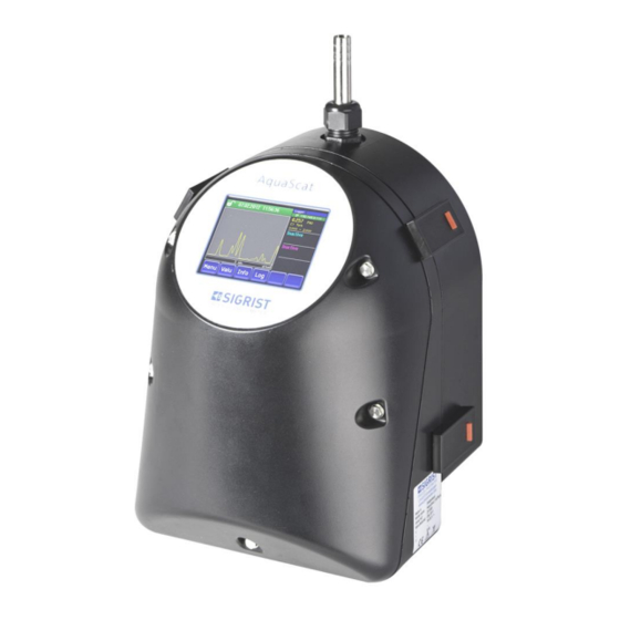
- Page 1 Document number: 11778E Version: 1 Valid from: 2012-04-01 INSTRUCTION MANUAL AquaScat 2 Versions: WTM / WTM A / HT Turbidimeter with non-contact measuring cell...
- Page 2 Copyright© SIGRIST-PHOTOMETER AG, subject to technical changes without notice 7/2017 SIGRIST-PHOTOMETER AG Tel. +41 41 624 54 54 Hofurlistrasse 1 +41 41 624 54 55 CH-6373 Ennetbürgen info@photometer.com Switzerland www.photometer.com...
-
Page 3: Table Of Contents
INSTRUCTION MANUAL AquaScat 2 Content General notes to the user ..................1 1.1. Purpose of the Instruction Manual ..............1 1.2. Target group ....................1 1.3. Additional documentation ................1 1.4. Copyright stipulations ..................1 1.5. Storage location of the Instruction Manual ............2 1.6. - Page 4 INSTRUCTION MANUAL AquaScat 2 General notes to the user 8.2. Check flow rate and cleanliness ..............49 8.3. Manual adjustment ..................52 8.4. Automatic adjustment for AquaScat 2 WTM A..........55 8.5. Clean parts which come into contact with water ..........56 8.6.
-
Page 5: General Notes To The User
C039 (mains device) and standards. 1.4. Copyright stipulations The Instruction Manual has been written by SIGRIST-PHOTOMETER AG. Copying or modify- ing the content or providing this document to third parties is permitted only with the express written consent of SIGRIST-PHOTOMETER AG. -
Page 6: Storage Location Of The Instruction Manual
INSTRUCTION MANUAL AquaScat 2 General notes to the user 1.5. Storage location of the Instruction Manual The Instruction Manual is a component of the product and should always be close at hand. The most recent version (in color) of the Reference Manual can be downloaded at www.photometer.com (one-time registration). -
Page 7: Proper Use
General notes to the user INSTRUCTION MANUAL AquaScat 2 1.8. Proper use The AquaScat 2 is designed for measuring turbidity during water treatment and is optimized for the values that occur in water treatment plants with regard to measurement span and environmental conditions. -
Page 8: Dangers When Not Used Properly
The instrument is not properly mounted. The instrument is not installed in accordance with the Instruction Manual. The instrument has been operated with accessory parts which SIGRIST-PHOTOMETER AG has not expressly recommended. Improper changes to the instrument have been performed. -
Page 9: Instrument Overview
Instrument overview INSTRUCTION MANUAL AquaScat 2 Instrument overview 2.1. Measuring station with optional accessory parts Figure 1: Measuring station with optional accessory parts Photometer with non-contact Docking station Section 4.3 measuring cell Sectio n 2.3/2.4 ... -
Page 10: Identification Aquascat 2
INSTRUCTION MANUAL AquaScat 2 Instrument overview 2.2. Identification AquaScat 2 The photometer is fitted with a rating plate: Figure 2: Rating plate on the AquaScat 2 Manufacturer Country of origin Product name Serial number Date of manufacture Service voltage ... -
Page 11: Scope Of Supply And Accessory Parts
Instrument overview INSTRUCTION MANUAL AquaScat 2 2.3. Scope of supply and accessory parts Scope of supply PCS. ART. NO. NAME VIEW VARIANT AquaScat 2 WTM 24 For high resolution / 118992 Low turbidity AquaScat 2 WTM A With automatic ad- 118993 24 VDC justment for high reso-... - Page 12 INSTRUCTION MANUAL AquaScat 2 Instrument overview PCS. ART. NO. NAME VIEW VARIANT Profibus DP interface print 119102 for AquaScat 2 Reference Manual Modbus RTU interfaces print 119103 for AquaScat 2 Reference Manual Current output 4 times for 119041 AquaScat 2 119045 24 VDC power supply 20 W...
-
Page 13: Technical Data
Instrument overview INSTRUCTION MANUAL AquaScat 2 2.4. Technical data TURBIDITY MEASUREMENT VALUES Measuring principle Scattered light measurement Measurement span 0 .. 4000 FNU Sample media Water Wavelength 880 nm, compliant with DIN EN ISO 7027 Radiation class LED device of Class 1 according to EN 60825-1 Measuring angle 90°... - Page 14 INSTRUCTION MANUAL AquaScat 2 Instrument overview AQUASCAT 2 WTM VALUES Display ¼ VGA with touchscreen Resolution: 320 x 240 pixels with 3.5” diagonal AQUASCAT 2 WTM A VALUES Automatic adjustment Photometer with automatic adjustment Other data identical to AquaScat 2 WTM AQUASCAT 2 HT VALUES Resolution...
-
Page 15: General Safety Pointers
General safety pointers 3.1. What to do in an emergency What to do in an emergency: SIGRIST-PHOTOMETER AG instruments have no On/Off switch. This is the responsibility of the customer. Before commissioning, clarify the following points: CAUTION! Clarify the position of the On/Off switch and the way it works. -
Page 16: Warning And Danger Symbols On The Instrument
INSTRUCTION MANUAL AquaScat 2 General safety pointers Property damage due to escaping sample. The instrument must never be connected to leaking sample tubes and operated. CAUTION! Damage to the touchscreen due to strong mechanical pressure. Do not apply excessive pressure to the touchscreen (touch lightly with your fingertip). Do not use pointed objects for manipulations on the touchscreen. -
Page 17: Mounting The Measuring Device
Mounting the measuring device INSTRUCTION MANUAL AquaScat 2 Mounting the measuring device 4.1. Location evaluation A note about selecting the right installation location: The sample feed should be as short as possible so that changes in the reading are dis- played without delay. - Page 18 INSTRUCTION MANUAL AquaScat 2 Mounting the measuring device WORKSTEP PROCEDURE Fasten the photometer onto 2.1: Position the photometer on the pre-mounted the pre-mounted mounting mounting bracket and pay attention to the two position- bracket. ing pins (circles). 2.2: Screw the photometer onto the mounting bracket. ...
-
Page 19: Mounting The Docking Station
Mounting the measuring device INSTRUCTION MANUAL AquaScat 2 WORKSTEP PROCEDURE 4.2: By turning the support (Y, picture above) adjust the instrument using a spirit level until it is vertical. Use the measuring cell housing as a support surface for the spirit level. 4.3: Tighten the fixing nut (X) of the support (Y). -
Page 20: Remove Optics Unit, Place On Docking Station
INSTRUCTION MANUAL AquaScat 2 Mounting the measuring device 4.4. Remove optics unit, place on docking station Figure 3: Fasten optics unit to docking station: Measuring cell component Optics unit Knurled screw for fastening the op- Docking station Section 4.3 tics unit 11778E/1... - Page 21 Mounting the measuring device INSTRUCTION MANUAL AquaScat 2 WORKSTEP PROCEDURE Loosen mounting clip and 1.1: Use a little force to push the release lock (red arrow) in remove optics unit the direction of the arrow (picture 1) and at the same time lift the mounting clip (picture 2).
-
Page 22: Mounting The Sample Connections
Mounting drawings in Section 15 4.5.2. Installation of the optional flow meter SIGRIST recommends installing a simple flow meter to regularly check the sample flow. Sections 2.1 and 2.3 Note the following points when mounting the flow meter: The flow meter is to be fastened before the sample inlet of the photometer. - Page 23 Mounting the measuring device INSTRUCTION MANUAL AquaScat 2 4.5.3. Attaching the sample connections to the photometer Figure 4: Overview of AquaScat 2 measuring cell unit Inlet tube Inlet tube conduit gland Holder for inlet tube Light trap ...
- Page 24 INSTRUCTION MANUAL AquaScat 2 Mounting the measuring device WORKSTEP PROCEDURE Fasten drain hose onto the photom- Fasten the drain hose on the drain tube (Figure eter. 4, 7) of the instrument. When doing so, press the outlet tundish (Figure 4, 5) downward with your hand so that the Flooding of the instrument drain tube (Figure 4, 7) is not pressed into the due to improper mounting of the...
-
Page 25: Installation Of The Optional Accessory Parts
Mounting the measuring device INSTRUCTION MANUAL AquaScat 2 4.6. Installation of the optional accessory parts 4.6.1. Information about installing the optional accessory parts Note the following when connecting the optional accessory parts: All hose connections have to be secured with hose clamps. The integrity of the con- CAUTION! nections should be checked about 2 weeks after installation to ensure that no air can be pulled in. -
Page 26: Electrical Installation
INSTRUCTION MANUAL AquaScat 2 Electrical installation Electrical installation 5.1. Safety pointers for the installation Life threatening voltage inside the instrument: Connecting electrical lines is extremely dangerous. Parts of the system can also be damaged. Local regulations must be observed at all times for electrical installations. DANGER! Further, the following basic principles must be observed: It is imperative that the protective conductor is connected. -
Page 27: Installation Procedure
Electrical installation INSTRUCTION MANUAL AquaScat 2 5.2. Installation procedure You can access the terminals by removing the front cover. Proceed as follows: WORKSTEP PROCEDURE Loosen the five screws on the front cover with a 7 mm key and remove the front cover. Establish the electrical connections as de- scribed in Section 5.3. -
Page 28: Connecting The Customer Connections
INSTRUCTION MANUAL AquaScat 2 Electrical installation 5.3. Connecting the customer connections Life threatening voltage inside the instrument: The photometer has no mains switch; hence the instrument is charged with voltage immedi- ately after being connected. DANGER! The cable lengths must be selected keeping in mind that the instrument is able to be mount- ed on the docking station. - Page 29 Electrical installation INSTRUCTION MANUAL AquaScat 2 Establish the electrical connections in the following sequence: TERMINALS MEANING REMARKS The relay outputs can be freely con- 1 – 2 – 3 Output 1 (relay contact 1) figured. Section 7.11 4 – 5 – 6 Output 2 (relay contact 2) 18, 19 Reading output 1...
-
Page 30: Connection Of The Optional Power Supply
INSTRUCTION MANUAL AquaScat 2 Electrical installation 5.4. Connection of the optional power supply Life threatening voltage inside the instrument: Connecting electrical lines can be extremely dangerous. Local regulations must be observed at all times for electrical installations. DANGER! Figure 6: Optional power supply open ... - Page 31 Electrical installation INSTRUCTION MANUAL AquaScat 2 Connecting the TERMINAL CABLE TERMINAL FUNCTION mains device: DESIGNATION IN COLOR DESIGNATION IN THE THE POWER PHOTOMETER SUPPLY +24V brown 8: 24 V 24 VDC blue 9: GND Ground Protective ground yellow-green 7: Ground connection Ground connection Protective ground Mains protective ground...
-
Page 32: Initial Start-Up
INSTRUCTION MANUAL AquaScat 2 Initial start-up Initial start-up The initial start-up with the web user interface via the Ethernet interface is described in the Reference Manual. Proceed with the initial start-up in accordance with the following table. If malfunctions oc- cur, please refer to Section 9. - Page 33 Initial start-up INSTRUCTION MANUAL AquaScat 2 WORKSTEP PROCEDURE Replace optics unit on photom- Replace the optics back on the measuring cell unit eter. and lock with the four mounting clips. Pay attention to the guide pins (see picture). Establish service voltage to the 6.1: Welcome screen appears.
- Page 34 INSTRUCTION MANUAL AquaScat 2 Initial start-up WORKSTEP PROCEDURE 6.3: Normal operation begins. Section 7.7 Set language. Section 7.8 Set current outputs. Section 7.9 Set limits. Section 7.10 Configure flow meter if present. Section 7.11 Set outputs 1 & 2 (relay out- puts).
-
Page 35: Operation
Operation INSTRUCTION MANUAL AquaScat 2 Operation 7.1. Operation basics In this document we only describe the practical examples for the first steps of the menu configuration. All other setting options are described in the Reference Manual. Operation using the web user interface is described in detail in the Reference Manual. Damage to the touchscreen caused by incorrect handling: Only touch the touch screen only with your fingers and not with sharp objects. - Page 36 INSTRUCTION MANUAL AquaScat 2 Operation 7.2.1. Menu button You reach the menu structure by pressing the Menu button and entering the access code. Now the instrument is in service operation. Operator prompting in service operation is described in Section 7.6. 7.2.2.
- Page 37 Operation INSTRUCTION MANUAL AquaScat 2 7.2.3. Functions of the log screen (Log button) The screen logger works independently of the data logger, which is set in the Logger menu and writes to the microSD card. The screen logger records the data of the last 32 days in one minute intervals. The data can be called up from the Log menu.
- Page 38 INSTRUCTION MANUAL AquaScat 2 Operation 7.2.4. Valu button By touching the Valu field, a numerical measuring value appears on the display. Section 7.4 7.2.5. Info button When you press the Info button, a general overview of the settings and configurations of the photometer appears.
-
Page 39: Activating And Deactivating The Screen Lock
Operation INSTRUCTION MANUAL AquaScat 2 7.3. Activating and deactivating the screen lock 2. Within one second press the button bot- 1. Press the lock icon top left. tom right. Depending on the initial state, the lock icon changes as follows: Display unlocked Display locked 11778E/1... -
Page 40: Display In Normal Operation
INSTRUCTION MANUAL AquaScat 2 Operation 7.4. Display in normal operation After switching on the instrument, it shows normal operation. The real-time measuring val- ues are continuously displayed. Figure 11: Displays in normal operation Measuring value Status line For values which are greater In normal operation the sta- than the maximum measuring range, tus line is green and shows the date... -
Page 41: Switching To Service Operation
Operation INSTRUCTION MANUAL AquaScat 2 7.5. Switching to service operation Definition The photometer is configured in the service mode. The measuring procedure is suspended Service mode and the main menus appear on the display. Proceed as follows for service operation: SUPPLEMENTARY MANIPULATION INFORMATION... -
Page 42: Control Components In Service Operation
INSTRUCTION MANUAL AquaScat 2 Operation 7.6. Control components in service operation 7.6.1. Entry element in service operation Figure 12: Menu structure Path specification Page number / total number of pages Main menus Instrument-specific menus of the Next page photometer. - Page 43 Operation INSTRUCTION MANUAL AquaScat 2 7.6.2. Numerical entry The following screen is for entering numbers and data: Figure 13: Numerical entry Display of the entered values. SI prefix: For entering very large or very small values. This can be done as follows: 1.
- Page 44 INSTRUCTION MANUAL AquaScat 2 Operation 7.6.3. Single or multiple selection with scroll bar Single selection The single selection is identifiable on the ESC button below right: The currently selected value is green. Use the Up/Down arrows to navigate the options in long lists. Use the ESC button to cancel the entry.
-
Page 45: Setting The Operating Language
Operation INSTRUCTION MANUAL AquaScat 2 7.7. Setting the operating language The following describes how to set the language of the menus and messages: SUPPLEMENTARY MANIPULATION INFORMATION Press the Menu button. Set the access code and confirm with OK. Factory setting is 0. Use the down arrow key to select the second page. -
Page 46: Setting The Current Outputs
INSTRUCTION MANUAL AquaScat 2 Operation 7.8. Setting the current outputs MANIPULATION SUPPLEMENTARY INFORMATION Press the Menu button. Set the access code and confirm with OK. Factory setting is 0. Press the Curr. outputs button. Select current output 1 or 2. For Inactive the current output is Select C1 Turb source. -
Page 47: Setting The Limits
Operation INSTRUCTION MANUAL AquaScat 2 7.9. Setting the limits So that the limits are not only displayed but also the outputs are switched, they have to be configured accordingly. Section 7.10 MANIPULATION SUPPLEMENTARY INFORMATION Press the Menu button. Set the access code and confirm with OK. Factory setting is 0. - Page 48 INSTRUCTION MANUAL AquaScat 2 Operation Upper and lower A maximum of two limits with upper threshold value of a and lower threshold values can be limit. programmed. If the operating mode is set to Ex- ceeded, then while the upper thresh- old value is exceeded the limit is active and remains active until the lower threshold value is again undershot.
-
Page 49: Configuring The Flow Meter With Limit Switch
Operation INSTRUCTION MANUAL AquaScat 2 7.10. Configuring the flow meter with limit switch The optional flow meter with limit switch is connected to terminals 22, 23 (In1). Proceed as follows to activate monitoring: MANIPULATION SUPPLEMENTARY INFORMATION Press the Menu button. Set the access code and confirm with OK. -
Page 50: Setting The Date And Time
INSTRUCTION MANUAL AquaScat 2 Operation MANIPULATION SUPPLEMENTARY INFORMATION Activate output functions (multiple selection Activated output functions are high- possible) lighted green. Invert: inverts the outputs Prio fault Fault Warning Service Adjustment Limit 1.2 The functions marked with MR refer to automatic measuring range switching and are described in the Reference Manual. -
Page 51: Setting Or Changing The Access Code
1 .. max. 6 digits Press the Meas button. Instrument again in normal operation. A forgotten access code can be cleared only by a SIGRIST service engineer! Enter your access code: 7.14. Back up configured data These measures can be of use to the service engineers for service purposes. -
Page 52: Servicing
INSTRUCTION MANUAL AquaScat 2 Servicing Servicing It is absolutely necessary to observe the following instructions when performing servicing duties: DANGER! Observe the safety pointers before performing servicing duties. The instrument must never be operated when the housing is removed. The instrument may be opened only by trained personnel. Perform the work steps in exactly in the order instructed. -
Page 53: Check Flow Rate And Cleanliness
Servicing INSTRUCTION MANUAL AquaScat 2 8.2. Check flow rate and cleanliness WORKSTEP PROCEDURE Remove the optics unit of the Section 4.4 photometer and fasten onto the docking station. Check flow rate of the sample If the flow rate is incorrect, please refer to Sec- according to the technical data tion 8.5. - Page 54 INSTRUCTION MANUAL AquaScat 2 Servicing WORKSTEP PROCEDURE Check whether water continual- ly flows at the overflow (X) and venting hose (Y). Perform this step only if a de- aeration tube with level control is present. Check light trap in the measur- ing cell for any residual water droplets (circle).
- Page 55 Servicing INSTRUCTION MANUAL AquaScat 2 WORKSTEP PROCEDURE Replace optics unit back onto Replace the optics unit back onto the measuring the photometer. cell unit and lock with the four mounting clips. Pay attention to the guide pins (see picture). 8.2.1. Flow rate reduction A reduction of the minimum flow rate from 2.5 l/min.
-
Page 56: Manual Adjustment
INSTRUCTION MANUAL AquaScat 2 Servicing 8.3. Manual adjustment WORKSTEP PROCEDURE Interrupt the sample supply to the photometer. Loosen conduit gland (X) and remove the inlet tube (Y). Section 4.4 Remove the optics unit of the photometer and fasten onto the docking station. 4.1: Inspect the checking unit to ensure it is clean and Install checking unit. - Page 57 Servicing INSTRUCTION MANUAL AquaScat 2 WORKSTEP PROCEDURE Re-mount optics unit on the Replace the optics unit back on the measuring cell unit photometer. and lock with the four mounting clips. Pay attention to the guide pins (see picture). Section 7.5 Switch photometer to ser- vice operation.
- Page 58 INSTRUCTION MANUAL AquaScat 2 Servicing WORKSTEP PROCEDURE Perform adjustment. Press the initiate button and wait. If the adjustment was successful, it is confirmed with Adjustment OK. This completes the adjustment. If the adjustment was not successful, it is indicated with Adjustment fault.
-
Page 59: Automatic Adjustment For Aquascat 2 Wtm A
Servicing INSTRUCTION MANUAL AquaScat 2 8.4. Automatic adjustment for AquaScat 2 WTM A The automatic adjustment is possible only with instrument type AquaScat 2 WTM A. The automatic adjustment can also be set for timed actuation in the Adjust interval menu. This is described in the Reference Manual. The following describes the manual initiation of the automatic adjustment: MANIPULATION SUPPLEMENTARY... -
Page 60: Clean Parts Which Come Into Contact With Water
INSTRUCTION MANUAL AquaScat 2 Servicing 8.5. Clean parts which come into contact with water The following describes cleaning the parts which come into contact with water (Remember however there are no windows to clean in the AquaScat WTM 2): WORKSTEP PROCEDURE Interrupt the sample sup- ply to the photometer. - Page 61 Servicing INSTRUCTION MANUAL AquaScat 2 WORKSTEP PROCEDURE 4.3: Loosen the conduit gland (D) and pull off the drain tube (E) downward. Clean parts which come Clean the removed parts or replace if necessary. into contact with water. When doing so, inspect the gasket in the outlet cone (ar- row).
- Page 62 INSTRUCTION MANUAL AquaScat 2 Servicing WORKSTEP PROCEDURE 6.2: Put the outlet cone (C) onto the drain tube (E) to the stop. When doing so, hold the drain tube from below. 6.3: Now press the outlet cone together with the drain tube downward to the stop.
-
Page 63: Check And Clean Optional Accessory Parts
Servicing INSTRUCTION MANUAL AquaScat 2 WORKSTEP PROCEDURE 7.2: Tighten the inlet tube (B) with the conduit gland (A). The inlet tube should protrude 5 mm out of the holder. Replace the optics unit back on the measuring cell unit and lock with the four mounting clips. -
Page 64: Clean The Optics
INSTRUCTION MANUAL AquaScat 2 Servicing 8.7. Clean the optics Figure 18: AquaScat 2 WTM/HT Figure 17: AquaScat 2 WTM A optics unit in adjust- ment position Transmitter Head of the automatic checking unit Stop for idle position of the check- Air filter ing unit ... - Page 65 Servicing INSTRUCTION MANUAL AquaScat 2 WORKSTEP PROCEDURE 4.1: Loosen the two screws (circles) and remove the Clean the transmitter. transmitter. 4.2: Clean the lens (arrow) on the transmitter with a cotton-tipped applicator moistened with ethanol. 4.3: After cleaning, place the transmitter on the posi- tioning pins (circles, picture above) and fasten with the two screws.
- Page 66 INSTRUCTION MANUAL AquaScat 2 Servicing WORKSTEP PROCEDURE 5.2: Clean the lens of the scattered light receiver with a cotton-tipped applicator moistened with ethanol. 5.3: Screw the aperture assembly into the optics hold- er clockwise. Ensure that the gasket on the aperture assembly is cor- rectly mounted (arrow).
- Page 67 Servicing INSTRUCTION MANUAL AquaScat 2 WORKSTEP PROCEDURE Put the checking unit in the 8.1: Change over the instrument to service operation adjustment position. as described in Section 7.5. 8.2: In the Simulation menu, select the Motor posi- tion submenu. Now select the Adjustment menu item.
- Page 68 INSTRUCTION MANUAL AquaScat 2 Servicing WORKSTEP PROCEDURE 10.3: Put the head of the checking unit on the position pins (arrows) and then fasten with the two screws. Place the optics unit again on the measuring cell unit and lock with the four mounting clips.
-
Page 69: Replace Air Filter
Servicing INSTRUCTION MANUAL AquaScat 2 8.8. Replace air filter WORKSTEP PROCEDURE Interrupt sample supply. Section 5 Interrupt the service voltage to the photometer. Section 4.4 Remove the optics unit of the photometer and fasten onto the docking station. 4.1: Remove fastening screws (circles) and filter Replace filter. -
Page 70: Change Battery
INSTRUCTION MANUAL AquaScat 2 Servicing 8.9. Change battery Life threatening voltage inside the instrument: Connecting the electrical lines is extremely dangerous. Parts of the system can also be dam- aged. Local regulations must be observed at all times for electrical installations. DANGER! WORKSTEP PROCEDURE... - Page 71 Servicing INSTRUCTION MANUAL AquaScat 2 WORKSTEP PROCEDURE Carefully mount front cover and fasten with the five screws. Damage to the threaded inserts in the housing due to excessive tight- ening of the front cover screws: Use a hex key without a T-handle to tight- en the screws of the front cover finger- 7 mm hex key tight (approx.
-
Page 72: Troubleshooting
INSTRUCTION MANUAL AquaScat 2 Troubleshooting Troubleshooting 9.1. Pinpointing the cause of a malfunction DETECTABLE MALFUNCTION MEASURES Check whether the service voltage is connected. No reading. Section 5 Check whether the fine-wire fuse in the instrument is OK. Section 9.2 Fault report in the display. -
Page 73: Replace Fine-Wire Fuse
Troubleshooting INSTRUCTION MANUAL AquaScat 2 9.2. Replace fine-wire fuse WORKSTEP PROCEDURE Section 5 Interrupt the service voltage to the pho- tometer. Loosen the five screws on the front cover with a 7 mm key and remove the front cover. Remove the old fine-wire fuse (circle) from the base print (AQBasi) and replace with a new one (type T2A). -
Page 74: Warning And Error Messages
INSTRUCTION MANUAL AquaScat 2 Troubleshooting 9.3. Warning and error messages 9.3.1. Warning messages and effect on operation WARNING: If a warning occurs during operation, it has the following effects: Warnings indicate an unusual state. The system continues to operate and delivers correct measuring values. - Page 75 Troubleshooting INSTRUCTION MANUAL AquaScat 2 9.3.2. Error messages and their effect on operation FAULT: If an error occurs during operation, it has the fol- lowing effects: A fault is a malfunction which prevents correct measurement value acquisition. The measuring values go to 0. The current output goes to the pro- grammed electrical current If fault.
- Page 76 INSTRUCTION MANUAL AquaScat 2 Troubleshooting 9.3.3. Prio messages (prioritized error messages) and their effect PRIO (PRIORITIZED FAULT): If a prioritized fault occurs during operation, it has the following effects: When there is a prioritized fault, the cause of the malfunction is serious. The measuring values go to 0.
-
Page 77: Customer Service Information
If this is not known, SIGRIST-PHOTOMETER AG customer service in Switzerland would be glad to provide you with a contact address. A current list of all SIGRIST country representatives is available on the Internet at www.photometer.com. Please have the following information ready when you contact a SIGRIST service point or customer service: The serial number of the photometer. -
Page 78: Decommissioning & Storage
INSTRUCTION MANUAL AquaScat 2 Decommissioning & storage 11. Decommissioning & storage Life threatening voltage inside the instrument: Connecting the electrical lines is extremely dangerous. Parts of the system can also be dam- aged. Local regulations must be observed at all times for electrical installations. DANGER! The aim of decommissioning is to prepare the instrument properly for storage and to con- serve it during storage. -
Page 79: Packaging & Transport
Packaging & transport INSTRUCTION MANUAL AquaScat 2 12. Packaging & transport The original packaging materials of the photometer should be used for packaging the pho- tometer and its peripheral components if possible. If the original packaging is no longer available, note the following information: Before packaging, close the openings of the photometer with adhesive tape or plugs so that no packaging materials can enter the instrument. -
Page 80: Disposal
INSTRUCTION MANUAL AquaScat 2 Disposal 13. Disposal Disposal of the photometer and its peripheral devices is to be carried out in compliance with regional statutory regulations. The photometer has no environmentally damaging sources of radiation. The materials listed below should be disposed of or recycled as described in the following table: CATEGORY MATERIALS DISPOSAL POSSIBILITIES... -
Page 81: Spare Parts
Spare parts INSTRUCTION MANUAL AquaScat 2 14. Spare parts The parts mentioned in this documentation and their article numbers are listed in the table below: ART.–NO. ARTICLE NAME REMARKS Section 8.9 116627 Air filter Section 8.5 116468 Inlet tube stainless steel 1.4435 ... -
Page 82: Appendix
INSTRUCTION MANUAL AquaScat 2 Appendix 15. Appendix The following section contains: Required drawings and dimension drawings for mounting. Servicing log 11778E/1... -
Page 83: Servicing Log
Appendix INSTRUCTION MANUAL AquaScat 2 15.1. Servicing log Servicing log Serial number: First commissioning: Remarks: Adjustment value Recal- ibr.1 Completed servicing duties Date Initials Before After 11778E/1... -
Page 84: Index
INSTRUCTION MANUAL AquaScat 2 Index 16. Index Flow rate monitoring ......25 Fuses, replace .........69 Access code, set ......47 AdjustInterval ........ 55 Adjustment, automatic ....55 HT (high turbidities) ......7 Air filter ........60 Air filter, replace ......65 Info, button ........34 Article numbers ...... - Page 85 Index INSTRUCTION MANUAL AquaScat 2 Service center ........ 73 Transport ........75 Service mode ......... 37 Servicing duties ......48 Use restrictions .........3 Servicing log........79 Servicing schedule ......48 Set language ......... 41 Warning symbols on the instrument 12 Shutter assembly ......60 Warnings ........70 Spare parts ........
- Page 86 SIGRIST-PHOTOMETER AG Tel. +41 41 624 54 54 Hofurlistrasse 1 +41 41 624 54 55 CH-6373 Ennetbürgen info@photometer.com Switzerland www.photometer.com...
Need help?
Do you have a question about the AquaScat 2 WTM Series and is the answer not in the manual?
Questions and answers