
Subscribe to Our Youtube Channel
Related Manuals for SIGRIST OilGuard 2 W


Summary of Contents for SIGRIST OilGuard 2 W
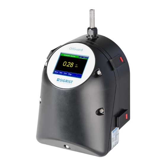
- Page 1 Document number: 14809E Version: 2 Valid from: S/N 625020 / SW V129 INSTRUCTION MANUAL OilGuard 2 W Oil trace monitor with free-fall measuring cell...
- Page 2 Copyright© SIGRIST-PHOTOMETER AG, subject to technical changes without notice 2/2019 SIGRIST-PHOTOMETER AG Tel. +41 41 624 54 54 Hofurlistrasse 1 +41 41 624 54 55 CH-6373 Ennetbürgen info@photometer.com Switzerland www.photometer.com...
-
Page 3: Table Of Contents
Designation of the photometer ............... 12 Scope of supply and accessories..............13 2.3.1 Standard scope of supply for the OilGuard 2 W ......... 13 2.3.2 Optional accessories for the OilGuard 2 W ..........14 Technical data for the OilGuard 2 W ............... 15 2.4.1... - Page 4 Checking the flow rate and cleanliness ............60 9.1.3 Manual adjustment ................... 62 9.1.4 Automatic adjustment with OilGuard 2 W A ..........64 9.1.5 Cleaning parts which come into contact with water ........65 9.1.6 Replacing the air filter ................68 9.1.7...
- Page 5 Contents Instruction Manual OilGuard 2 W 14 Disposal ........................79 15 Spare parts list ......................80 15.1 Spare parts for the OilGuard 2 W..............80 16 Index ........................... 81 Makro 14809E/2...
- Page 6 Instruction Manual OilGuard 2 W Contents This pa ge is inte ntionally bla nk Makro 14809E/2...
-
Page 7: General User Information
Purpose of the Instruction Manual This Instruction Manual provides the user with helpful information about the entire life cycle of the OilGuard 2 W and its peripheral devices. Before commissioning the instrument, you should be completely familiar with the Instruction Manual. -
Page 8: Order Document
It can also be ordered from a SIGRIST representative in your country ( Instruction Manual “Customer service information”). Proper use The OilGuard 2 W is designed for measuring oil traces during water treatment and is opti- mized for the values that occur in water treatment plants with regard to measuring scope and ambient conditions. -
Page 9: Dangers When Not Used Properly
The instrument is not properly mounted, set up or transported. The instrument is not installed and operated in accordance with the Instruction Manual. The instrument has been operated with accessory parts which SIGRIST-PHOTOMETER AG has not expressly recommended. Improper changes to the instrument have been performed. -
Page 10: Meaning Of The Pictograms
1.14 Meaning of the pictograms All pictograms used in this document are explained below: Additional information about the current topic. Practical procedures when working with the OilGuard 2 W. Manipulations on the touchscreen. The screenshot is an example and may differ from current device. -
Page 11: Instrument Overview
Instrument overview Instruction Manual OilGuard 2 W Instrument overview Overview of the OilGuard 2 W Figure 1: Measuring point with optional accessories Photometer with free-fall measur- Outlet ing cell Sample inlet of the level control Sample overflow of the level control ... -
Page 12: Designation Of The Photometer
Instruction Manual OilGuard 2 W Instrument overview Designation of the photometer The photometer is fitted with the following rating plate: Figure 2: Rating plate on OilGuard 2 W Manufacturer Country of origin Product name Serial number ... -
Page 13: Scope Of Supply And Accessories
Instrument overview Instruction Manual OilGuard 2 W Scope of supply and accessories 2.3.1 Standard scope of supply for the OilGuard 2 W PCS. ART. NO. NAME VIEW VARIANT 121250 OilGuard 2 W with set for wall mounting and lev- el control... -
Page 14: Optional Accessories For The Oilguard 2 W
Instruction Manual OilGuard 2 W Instrument overview 2.3.2 Optional accessories for the OilGuard 2 W PCS. ART. NO. NAME VIEW VARIANT 121233 Set for wall mounting and lev- el control on the OilGuard 2 W 121255 Checking unit for Manual calibration... -
Page 15: Technical Data For The Oilguard 2 W
Instrument overview Instruction Manual OilGuard 2 W Technical data for the OilGuard 2 W Fluorescence measure- Values ment Measuring principle Fluorescence measurement Measuring scope 0 .. 50 µg/l (ppb) with 16 EPA-PAH calibration Wavelength Excitation: 280 nm (EN 62471 Risk Group 3 – High Risk) Detection: 300 –... -
Page 16: Typical Measuring Values And Calculation Factors
Instruction Manual OilGuard 2 W Instrument overview Photometer Values Outputs Outputs: Optional 4-way current 4 x 0/4 .. 20 mA, galvanically isolated up to max. 50 V rela- output module tive to ground, max. 500 Ω burden Measuring ranges... -
Page 17: General Safety Points
Check that there are no leaks. CAUTION! Moisture and condensation on electronic components during operation. Damage may occur if moisture enters the inside of the OilGuard 2 W. CAUTION! Penetration of moisture as well as condensation on the electrical components dur- ing servicing duty. -
Page 18: Danger Due To Uv Radiation
Instruction Manual OilGuard 2 W General safety points The use of aggressive chemicals when cleaning. Use of aggressive chemicals can cause damage to instrument components. Do not use aggressive chemicals or cleaning agents when cleaning. CAUTION! Should the instrument come in contact with aggressive chemicals, clean it thoroughly with a neutral cleaning agent. -
Page 19: Preventing Undesirable Online Access Attempts
Instruction Manual OilGuard 2 W Preventing undesirable online access attempts SIGRIST instruments are equipped with an integrated web user interface and Mod- bus TCP interface, thus offering state-of-the-art administration and control possibil- ities. However, if these are connected directly to the Internet, then any Internet us- er can in principle access your instrument and change the configuration. -
Page 20: Mounting
Screw on the mounting bracket at the desired position. The mounting bracket must be hori- zontally aligned with a spirit level. Align the OilGuard 2 W to the two positioning pins (circles), then screw onto the mounting bracket. Remove the optics unit from the OilGuard 2 W according to Section 9.1.1. -
Page 21: Mounting The Docking Station
Mounting Instruction Manual OilGuard 2 W WORKSTEP ADDITIONAL INFO / IMAGES Align the OilGuard 2 W as follows: 1. Loosen the fixing nut (X) of the support (Y). 2. By turning the support (Y, figure right), adjust the instrument using a spirit level until it is straight. -
Page 22: Mounting The Sample Connections
Instruction Manual OilGuard 2 W Mounting Mounting the sample connections 4.4.1 General information on the sample connections Flooding of the surrounding area due to improper connection of the sample con- nections. Note the following when fastening the hoses: The outlet hose must be fastened so that the flood protection holes are not covered. -
Page 23: Fastening The Sample Connections On The Oilguard 2 W
Mounting Instruction Manual OilGuard 2 W 4.4.2 Fastening the sample connections on the OilGuard 2 W Figure 3: Overview of the measuring cell unit Inlet pipe Conduit gland for inlet pipe Holder for inlet pipe Light trap ... -
Page 24: Mounting The Optional Accessories
Instruction Manual OilGuard 2 W Mounting The following procedure describes how to mount the sample connections on the OilGuard 2 W: WORKSTEP ADDITIONAL INFO / IMAGES Remove the optics unit according to Section 9.1.1 and fasten on the docking sta- Warning! UV radiation. -
Page 25: Electrical Installation
Electrical installation Instruction Manual OilGuard 2 W Electrical installation Safety pointers for the electrical connection Connecting the service voltage. Improper connection of the service voltage can be potentially fatal. The system may also be damaged. Local regulations for electrical connection must be observed at all times. -
Page 26: Removing And Reattaching The
Instruction Manual OilGuard 2 W Electrical installation Removing and reattaching the front cover Life-threatening voltage inside the instrument. The system has no mains switch, meaning it is charged with voltage immediately after the electrical connections have been established. DANGER! The terminals are accessed by removing the front cover. The following describes this process:... -
Page 27: Connecting The Customer Connections
Electrical installation Instruction Manual OilGuard 2 W Connecting the customer connections Life-threatening voltage inside the instrument. The system has no mains switch, meaning it is charged with voltage immediately after the electrical connections have been established. DANGER! Figure 4: Position of the customer terminals ... - Page 28 Instruction Manual OilGuard 2 W Electrical installation The front cover must first be removed from the OilGuard 2 W according to Section 5.2. Es- tablish the electrical connections in the following sequence: TERMINALS MEANING REMARKS 1 – 2 – 3...
-
Page 29: Connecting The Optional 24 Vdc Power Supply
Electrical installation Instruction Manual OilGuard 2 W Connecting the optional 24 VDC power supply Life-threatening voltage due to accidentally released voltage-carrying wires. The wires of the supply connection must be secured with cable ties so that if one wire accidentally becomes loose no other parts can be charged with voltage. - Page 30 Instruction Manual OilGuard 2 W Electrical installation The terminals are assigned as follows for connecting the power supply: Terminal designa- Cable color Terminal designation in Function tion in the power the photometer supply +24 V Brown 8: 24 V 24 VDC...
-
Page 31: Connecting The Field Bus Interfaces (Optional)
Electrical installation Instruction Manual OilGuard 2 W Connecting the field bus interfaces (optional) Information on commissioning the field bus interfaces can be found in the Reference Handbook. 5.5.1 Overview of Modbus RTU and Profibus DP Figure 6: Overview of field bus interfaces ... -
Page 32: Connecting The Modbus Rtu Or Profibus Dp
Instruction Manual OilGuard 2 W Electrical installation 5.5.2 Connecting the Modbus RTU or Profibus DP The terminals on the Profibus DP or Modbus RTU module are assigned as follows: TERMINALS MODBUS / PROFIBUS FUNCTIONAL DESCRIPTION Ground IN Connection for cable shielding... -
Page 33: Overview Of Hart
Electrical installation Instruction Manual OilGuard 2 W 5.5.4 Overview of HART Information on commissioning the field bus interfaces can be found in the Reference Handbook. Figure8: Position of the HART module in the SICON (M) Field bus interface (connection HART terminals print) for HART. -
Page 34: Connecting The Analog Modules (Optional)
Instruction Manual OilGuard 2 W Electrical installation Connecting the analog modules (optional) 5.6.1 Overview of 4-way current output The configuration of the current outputs is described in the Section 8.2. Figure 9: Overview of the 4-way current output module ... -
Page 35: Commissioning
Section 9.1.2 and shutter are clean. There must be no pressure surge when turning the water off and on! Make sure that the OilGuard 2 W is correctly Section 4/ Section 5 mounted and that the electrical connections are correctly connected. - Page 36 Instruction Manual OilGuard 2 W Commissioning WORKSTEP ADDITIONAL INFO / IMAGES Establish the service voltage to the system. 6.1: Establish the service voltage to the instru- ment. The welcome screen appears on the dis- play. The factory setting language is English. Accord- ingly, the displayed language during the initial start-up is English.
-
Page 37: Operation
Operation Instruction Manual OilGuard 2 W Operation Operation basics In this document we describe the practical examples only for the first steps of the menu con- figuration. All other setting options are described in the Reference Handbook. Operation us- ing the web user interface is described in detail in the Reference Manual. -
Page 38: Control Elements In Measuring Operation
Instruction Manual OilGuard 2 W Operation Control elements in measuring operation Figure 10: Control elements in measuring operation Menu button Valu button Calls up the menu structure. Sec- Numerical representation of the meas- tion 7.3 uring values. Section 7.4 ... -
Page 39: Info Button
Operation Instruction Manual OilGuard 2 W Info button When you press the Info button, a general overview of the instrument settings appears. These are described below: 7.5.1 Info button, screen 1 Figure 11: Info button, screen 1 ... -
Page 40: Info Button
Instruction Manual OilGuard 2 W Operation 7.5.2 Page 2, Info button Figure 12: Info screen, page 2 Contact information Display of up to 5 pending fault mes- sages 14809E/2... -
Page 41: Diag Button
Operation Instruction Manual OilGuard 2 W Diag button When you press the Diag button, a diagram appears which graphically shows the measuring values over a certain period of time. Figure 13: Graphic representation of the measuring values ... -
Page 42: Functions Of The Log Screen (Log Button)
Instruction Manual OilGuard 2 W Operation Functions of the log screen (Log button) The screen logger works independently of the data logger, which is set in the Logger menu and writes to the microSD card. The screen logger records the data of the last 32 days in one-minute intervals. The data can be called up from the Log menu. -
Page 43: Displays In Measuring Operation
Operation Instruction Manual OilGuard 2 W Displays in measuring operation Figure 15: Displays in measuring operation Measuring value(s) Status line For values which are greater than In measuring operation, the status line the maximum measuring range, no is green and shows the date and time. -
Page 44: Lock / Unlock The Touch Screen
Instruction Manual OilGuard 2 W Operation Lock / unlock the touch screen MANIPULATION Press the lock icon top left. Within one second press the key bottom at the outside right. Depending on the initial state, the lock icon changes as follows:... -
Page 45: Switching To Service Mode
Operation Instruction Manual OilGuard 2 W 7.10 Switching to service mode The system is configured in service operation. The measuring procedure is interrupted and the main menus appear on the display. Service operation is accessed as follows: MANIPULATION ADDITIONAL INFO / IMAGES Press the Menu button. -
Page 46: Control Components In Service Mode
Instruction Manual OilGuard 2 W Operation 7.11 Control components in service mode 7.11.1 Input elements in service mode Figure 16: Input elements in service mode Path specification Page number / total number of pages ... -
Page 47: Numerical Entry
Operation Instruction Manual OilGuard 2 W 7.11.2 Numerical entry The following screen is for entering numbers and data: Figure 17: Numerical entry Parameter name Entered values Prefix: For entering very large or Numerical entry very small values. -
Page 48: Single Selection Of Functions
Instruction Manual OilGuard 2 W Operation 7.11.3 Single selection of functions The single selection is identifiable by the ESC button below right. The currently selected function is green. Use the Up/Down arrows to navigate the options in long lists. Use the ESC button to cancel the entry. -
Page 49: Settings
Settings Instruction Manual OilGuard 2 W Settings Setting the operating language MANIPULATION ADDITIONAL INFO / IMAGES Press the Menu button. Set the access code and confirm with OK. Factory setting is 0. Press the Configuration button to access lan- If the desired menu does not guage selection. -
Page 50: Setting The Current Outputs
Instruction Manual OilGuard 2 W Settings Setting the current outputs MANIPULATION ADDITIONAL INFO / IMAGES Press the Menu button. Set the access code and confirm with OK. Factory setting is 0. Press the Curr. outputs button. If the desired menu does not appear, press the arrow at the bot- tom right. -
Page 51: Setting The Limits
Settings Instruction Manual OilGuard 2 W Setting the limits The limits have to be configured accordingly so that they are not only displayed, but that the outputs are also switched. Section 8.4 MANIPULATION ADDITIONAL INFO / IMAGES Press the Menu button. -
Page 52: Upper And Lower Threshold Value Of A Limit
Instruction Manual OilGuard 2 W Settings 8.3.1 Upper and lower threshold value of a limit A maximum of eight limits with upper and lower threshold values can be programmed. If the operating mode is set to Exceeded, then while the upper threshold value is ex-... -
Page 53: Setting The Outputs (Digital)
Settings Instruction Manual OilGuard 2 W Setting the outputs (digital) Outputs 1/2 are located on the AQ2Basi print near the customer connection terminals and are designated as relays 1 and 2. MANIPULATION ADDITIONAL INFO / IMAGES Press the Menu button. -
Page 54: Setting The Date And Time
Instruction Manual OilGuard 2 W Settings Setting the date and time MANIPULATION ADDITIONAL INFO / IMAGES Press the Menu button. Set the access code and confirm with OK. Factory setting is 0. Press the Configuration button. If the desired menu does not appear, press the arrow bottom right. -
Page 55: Setting Or Changing The Access Code
Enter the access code and confirm with OK. Press the Meas button. The instrument is in measuring op- eration again. A forgotten access code can be cleared only by a SIGRIST service engineer. Enter your personal access code here: 14809E/2... -
Page 56: Backup Configured Data
Instruction Manual OilGuard 2 W Settings Backup configured data These measures can be of use to the service engineers for service purposes. MANIPULATION ADDITIONAL INFO / IMAGES Press the Menu button. Set the access code and confirm with OK. Factory setting is 0. -
Page 57: Servicing
Replacing the air filter. Obligatory measure for main- needed taining functional efficiency. Section 9.1.6 Every 10 years Operator Replacing the battery. Obligatory measure for main- or as needed taining functional efficiency. Section 9.1.7 Table 1: Servicing schedule for OilGuard 2 W 14809E/2... -
Page 58: Fastening The Optics Unit To The Docking Station
Exposure of longer than 3 seconds can lead to permanent damage to the eyes and skin. The UV LED is only accessible when the housing is open. The OilGuard 2 W is equipped with an automatic cut-off device that puts the LED out of operation when the housing is UV RADIATION open. - Page 59 Servicing Instruction Manual OilGuard 2 W The optics unit is mounted on the docking station as follows: WORKSTEP ADDITIONAL INFO / IMAGES Open the mounting clips (circle in figure be- low) as follows: Use a little force to push the red safety catch in the direction of the arrow (figure 1) and at the same time lift the mounting clip (figure 2).
-
Page 60: Checking The Flow Rate And Cleanliness
Instruction Manual OilGuard 2 W Servicing 9.1.2 Checking the flow rate and cleanliness The following procedure describes how the flow rate is checked: WORKSTEP ADDITIONAL INFO / IMAGES Remove the optics unit on the photometer according to Section 9.1.1 and fasten on the Danger due to UV radia- docking station. - Page 61 Servicing Instruction Manual OilGuard 2 W WORKSTEP ADDITIONAL INFO / IMAGES Check the shutter assembly for residual water (circle). Remove any residues with a cloth. Place the optics unit back on the measuring cell unit and lock with the four mounting clips.
-
Page 62: Manual Adjustment
Instruction Manual OilGuard 2 W Servicing 9.1.3 Manual adjustment The following procedure describes how manual adjustment is made with an OilGuard 2 W. WORKSTEP ADDITIONAL INFO / IMAGES Interrupt the sample supply to the photome- ter. Loosen the conduit gland (X) and remove the inlet pipe (Y). - Page 63 Nominal value corresponds to the value of the checking unit? Large temperature difference between the OilGuard 2 W and the checking unit. Soiled optics in the instrument? In this case, contact customer service. Remove the checking unit from the photome- ter again.
-
Page 64: Automatic Adjustment With Oilguard 2 W A
9.1.4 Automatic adjustment with OilGuard 2 W A Automatic adjustment is only possible with the instrument type OilGuard 2 W A. The au- tomatic adjustment can also be set for time actuation in the Adjust interval menu. This is described in the Reference Manual. -
Page 65: Cleaning Parts Which Come Into Contact With Water
Servicing Instruction Manual OilGuard 2 W 9.1.5 Cleaning parts which come into contact with water The following describes cleaning the parts of the OilGuard 2 W that come into contact with water: WORKSTEP ADDITIONAL INFO / IMAGES Interrupt the sample supply to the photome- Section 4.4... - Page 66 Instruction Manual OilGuard 2 W Servicing WORKSTEP ADDITIONAL INFO / IMAGES Loosen the conduit gland (D) and remove the outlet pipe (E) by pulling it downwards. Clean the removed parts or replace if neces- sary. When doing so, also inspect the seal in the outlet cone (arrow).
- Page 67 Servicing Instruction Manual OilGuard 2 W WORKSTEP ADDITIONAL INFO / IMAGES Fasten this unit by tightening the conduit gland. At position X, there should now be no space between the outlet cone and the conduit gland! Insert the inlet pipe (B) from above into the conduit gland (A) up to the stop.
-
Page 68: Replacing The Air Filter
Instruction Manual OilGuard 2 W Servicing 9.1.6 Replacing the air filter The following describes the replacement of the air filter: WORKSTEP ADDITIONAL INFO / IMAGES Interrupt the sample feed to the photometer. Section 4.4 Interrupt the service voltage to the photome- Section 5 ter. -
Page 69: Replacing The Battery
Servicing Instruction Manual OilGuard 2 W 9.1.7 Replacing the battery Danger due to electrical shock that may result in serious bodily injury or death. External signal lines may carry life threatening voltage even if the voltage supply to the in- strument is disconnected. - Page 70 Instruction Manual OilGuard 2 W Servicing WORKSTEP ADDITIONAL INFO / IMAGES Carefully mount the cover and fasten with the five screws. Damage to the threaded inserts in the housing due to excessive tightening of the screws on the cover: Use a hex key without a T-handle to tighten...
-
Page 71: Troubleshooting
Troubleshooting Instruction Manual OilGuard 2 W 10 Troubleshooting 10.1 Pinpointing malfunctions DETECTABLE MALFUNCTION ACTION No reading Check whether the supply voltage is present. Error message in the display Analyze the error message. Section 10.2 to Section 10.4 ... -
Page 72: Warning Messages And Effect On Operation
Instruction Manual OilGuard 2 W Troubleshooting 10.2 Warning messages and effect on operation Warnings indicate an unusual state. WARNINGS If a warning occurs during operation, it has the follow- ing effects: The system continues to operate. However, the measuring results must be evaluated with caution. -
Page 73: Fault Messages And Effect On Operation
Troubleshooting Instruction Manual OilGuard 2 W 10.3 Fault messages and effect on operation FAULT If a fault occurs during operation, it has the following effects: A fault is a malfunction which prevents correct measurement value acquisition. The measuring values of the concerned photome- ter go to 0. -
Page 74: Prioritized Fault Messages And Their Effect On Operation
Instruction Manual OilGuard 2 W Troubleshooting 10.4 Prioritized fault messages and their effect on operation When there is a prioritized fault, the cause of the malfunction is serious. CAUTION! PRIO (PRIORITIZED FAULT) If a prioritized fault occurs during operation, it has the following effects: ... -
Page 75: Replacing The Fine-Wire Fuses
Troubleshooting Instruction Manual OilGuard 2 W 10.5 Replacing the fine-wire fuses The following describes the replacement of the fine-wire fuse on the AQ2Basi print: WORKSTEP ADDITIONAL INFO / IMAGES Interrupt the service voltage to the photome- Section 5 ter. Loosen the five screws (circles) with a 7 mm key and remove the cover. -
Page 76: Customer Service Information
A current list of all SIGRIST country representatives is available online at www.photometer.com. Please have the following information ready when you contact a SIGRIST service point or customer service: ... -
Page 77: Decommissioning/Storage
Interrupt the sample feed to the OilGuard 2 W and remove the inlet and outlet hose. All surfaces which come into contact with the sample must be thoroughly cleaned. -
Page 78: Packaging/Transport/Returning
The original packaging materials should be used for packaging the OilGuard 2 W if possible. If the original packaging is no longer available, note the following information: ... -
Page 79: Disposal
Disposal Instruction Manual OilGuard 2 W 14 Disposal Disposal of the system and its peripheral devices is to be carried out in compliance with re- gional statutory regulations. The system has no environmentally damaging sources of radiation. The materials listed be-... -
Page 80: Spare Parts List
Section 9.1.6 116468 Inlet pipe, stainless steel 1.4435 Section 9.1.5 116833 Inlet pipe, PVC Section 9.1.5 121297 Bent inlet tube for OilGuard 2 W with wall Section 9.1.5 mounting set 117988 Outlet pipe with flood protection, Section 9.1.5 complete 117442 Fuse, microfuse 250 V 2 AT RM5 Section 10.5... - Page 81 Spare parts list Instruction Manual OilGuard 2 W This pa ge is inte ntionally bla nk 14809E/2...
-
Page 82: Index
Instruction Manual OilGuard 2 W Index 16 Index 4-way current output ........... 34 Improper use ............9 Initial start-up ............35 Inlet pipe ............. 23 Installation, electrical ........... 25 Access code, set ........... 55 Internet security ..........19 Analog modules ........... 34 Article numbers ............ - Page 83 Index Instruction Manual OilGuard 2 W Save data ............. 56 Touchscreen ............37 Scope of supply ............ 13 Transport ............78 Scope of supply, standard ........13 Typical measuring values ........16 Screen lock ............44 Service center ............76 Service mode ............
- Page 84 SIGRIST-PHOTOMETER AG Tel. +41 41 624 54 54 Hofurlistrasse 1 +41 41 624 54 55 CH-6373 Ennetbürgen info@photometer.com Switzerland www.photometer.com...
Need help?
Do you have a question about the OilGuard 2 W and is the answer not in the manual?
Questions and answers