
Related Manuals for SIGRIST AquaScat S


Summary of Contents for SIGRIST AquaScat S
- Page 1 Document number: 13798E Version: 3 Valid from: S/N 283010 / SW 129 INSTRUCTION MANUAL AquaScat S Turbidity probe for water treatment...
- Page 2 Copyright© SIGRIST-PHOTOMETER AG, subject to technical changes without notice 2/2019 SIGRIST-PHOTOMETER AG Tel. +41 41 624 54 54 Hofurlistrasse 1 +41 41 624 54 55 CH-6373 Ennetbürgen info@photometer.com Switzerland www.photometer.com...
-
Page 3: Table Of Contents
5.2.1 Opening the Conn-R junction box ............. 35 5.2.2 Overview of the Conn-R junction box ............36 5.2.3 Connecting the AquaScat S to the Conn-R junction box ......37 5.2.4 Customer connections on the Conn-R junction box ........38 13798E/3... - Page 4 Instruction Manual AquaScat S Contents Installation of the AquaScat S with SICON (M) ..........39 5.3.1 Removing the cover from the SICON (M) ........... 39 5.3.2 Overview of the opened SICON control unit ..........40 5.3.3 Installing the AquaScat S on the SICON (M) ..........41 5.3.4...
- Page 5 Replacing the desiccant and gasket on the AquaScat S ........77 Replacing the desiccant on the submerge tube version with special cable ..78 Cleaning the AquaScat S ................80 Removing and reinserted the AquaScat S from the extractable assembly ..82 Carrying out recalibration ................87 9.6.1 Overview of recalibration ................
- Page 6 Instruction Manual AquaScat S Contents This pa ge is inte ntionally bla nk Makro 13798E/3...
-
Page 7: General User Information
Purpose of the Instruction Manual This Instruction Manual provides the user with helpful information about the entire life cycle of the AquaScat S and its peripheral devices. Before commissioning the instrument, you should be completely familiar with the Instruction Manual. -
Page 8: Order Document
The most recent version of this document can be downloaded at www.photometer.com (first time registration required). It can also be ordered from a SIGRIST representative in your country ( Instruction Manual “Customer service information”). Proper use The AquaScat S and its peripherals are designed for measuring the turbidity of water. -
Page 9: Dangers When Not Used Properly
The instrument is not properly mounted, set up or transported. The instrument is not installed and operated in accordance with the Instruction Manual. The instrument has been operated with accessory parts which SIGRIST-PHOTOMETER AG has not expressly recommended. Improper changes to the instrument have been performed. -
Page 10: Meaning Of The Pictograms
1.14 Meaning of the pictograms All pictograms used in this document are explained below: Additional information about the current topic. Practical procedures when working with the AquaScat S. Manipulations on the touchscreen. The screenshot is an example and may differ from current device. -
Page 11: Instrument Overview
Instrument overview Instruction Manual AquaScat S Instrument overview Overview of a measuring point Figure 1: Overview of a measuring point AquaScat S turbidity probe Conn-R junction box (optional) including 10 m cable SICON-C portable control unit (op-... -
Page 12: Designation Of The Components
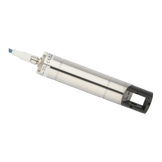
Instruction Manual AquaScat S Instrument overview Designation of the components 2.2.1 Designation of the AquaScat S The photometer is fitted with the following rating plate: Figure 2: Rating plate on AquaScat S CE mark Manufacturer Observe the Instruction Manual ... -
Page 13: Designation Of The Conn-R Junction Box
Instrument overview Instruction Manual AquaScat S 2.2.2 Designation of the Conn-R junction box The Conn-R junction box is fitted with the following rating plate: Figure 3: Rating plate on Conn-R junction box Manufacturer Country of origin ... -
Page 14: Designation Of The Sicon-C
Instruction Manual AquaScat S Instrument overview 2.2.3 Designation of the SICON-C The SICON-C portable control unit is fitted with the following rating plate: Figure 4: Rating plate on SICON-C Manufacturer Country of origin Product name Serial number ... -
Page 15: Scope Of Supply And Accessories
Instrument overview Instruction Manual AquaScat S Scope of supply and accessories 2.3.1 Standard scope of supply for the AquaScat S PCS. ART. NO. NAME VIEW VARIANT 120498 AquaScat S including device cable, 8-pin, 10 m with connector Documents: PCS. DOC. NO. - Page 16 Instruction Manual AquaScat S Instrument overview PCS. ART. NO. NAME VIEW VARIANT 118342 SICON control unit 119040 SICON M multi- channel control unit 118442 Profibus DP inter- For SICON (M) only faces print 118445 Modbus RTU inter- For SICON (M) only...
- Page 17 Instrument overview Instruction Manual AquaScat S Adapter for connecting to a water line or sampling point: PCS. ART. NO. NAME VIEW VARIANT 120561 PE fitting 120562 Pipe flange 120563 Submerge tube 1 m (standard equipment) 120564 Submerge tube extension 1 m ®...
-
Page 18: Technical Data
Instruction Manual AquaScat S Instrument overview Technical data Turbidity measure- Values ment Measuring principle Scattered light measurement Measurement span 0 .. 4000 FNU Sample medium Water Wavelength 860 nm, compliant with DIN EN ISO 7027 Measuring angle 90° AquaScat S... - Page 19 Instrument overview Instruction Manual AquaScat S SICON (M, C) Values Service voltage 24 VDC ± 10 % Display ¼ VGA with touchscreen Resolution: 320 x 240 pixels with 3.5" diagonal Outputs/inputs Outputs: (not for SICON-C) 4 x 0/4 .. 20 mA, galvanically isolated up to max. 50 V relative to ground and max.
- Page 20 Instruction Manual AquaScat S Instrument overview Conn-R junction box Values Service voltage 24 VDC ± 10 % Power consumption 0.5 W + photometer Outputs 2 x relay outputs 230 VAC, 4 A 1 x current output (from photometer)
-
Page 21: General Safety Points
General safety points Instruction Manual AquaScat S General safety points Dangers when properly used Damaged instrument or cabling. Touching damaged cables may lead to electrical shocks or death. The instrument may be operated only when the cables are undamaged. -
Page 22: Residual Risk
Instruction Manual AquaScat S General safety points Moisture and condensation on electronic components during operation. Damage may occur if moisture enters the inside of the AquaScat S. CAUTION! Penetration of moisture as well as condensation on the electrical components dur- ing servicing duty. -
Page 23: Preventing Undesirable Online Access Attempts
Instruction Manual AquaScat S Preventing undesirable online access attempts SIGRIST instruments are equipped with an integrated web user interface and Mod- bus TCP interface, thus offering state-of-the-art administration and control possibil- ities. However, if these are connected directly to the Internet, then any Internet us- er can in principle access your instrument and change the configuration. -
Page 24: Mounting
Mounting Basic information for mounting the AquaScat S Figure 5: Mounting directions The following points must be observed when mounting the AquaScat S: The photometer should be mounted in positions where there is a uniform flow. This is usually the case in the standpipe (pos. 1). The photometer can also be installed in pipes that run horizontally (pos. -
Page 25: Mounting The Pe Fitting
Mounting Instruction Manual AquaScat S Mounting the PE fitting For mounting on the pipe, the PE100 screw-in fitting (pos. 3) must be welded onto the pipe-T-piece (pos. 2) beforehand according to the AquaScat_S_PE-MB drawing. Mounting of the PE fitting can be made according to the AquaScat_S_PE-MB dimensional drawing. -
Page 26: Mounting The Pipe Flange
For mounting on the pipe, a T-piece (pos. 2) with pipe flange must be welded onto the pipe beforehand according to the AquaScat_S_RF-MB drawing. Mounting of the AquaScat S can be made according to the AquaScat_S_RF-MB dimension- al drawing. Figure 7: Overview of a measuring point with connection via pipe flange ... -
Page 27: Mounting The Extractable Assembly
Mounting Instruction Manual AquaScat S Mounting the extractable assembly 4.4.1 Extractable assembly: Mounting the probe in a vertical pipe A 2" threaded coupling (pos. 2) must be welded onto the pipe beforehand according to the AquaScat_S_WA-MB drawing. Before mounting the extractable assembly, remove the probe as detailed in Section 9.5(step 1 to 8). -
Page 28: Extractable Assembly: Mounting The Probe In A Horizontal Pipe
Instruction Manual AquaScat S Mounting 4.4.2 Extractable assembly: Mounting the probe in a horizontal pipe On horizontal pipes, the handle on the probe must be turned by 90°. This can be done as follows: WORKSTEP ADDITIONAL INFO / IMAGES Loosen the screw (X) so that the handle can be turned easily. -
Page 29: Mounting The Submerge Tube
Feed the connection cable through the sub- merge tube. Connect the cable to the AquaScat S and firm- ly tighten the screw connection. Insert the AquaScat S in the submerge tube. Pull the cable through the cable gland on the end cap. -
Page 30: Installing The Submerge Tube
The supplied pipe clamp (pos. 4) can be used to fasten the submerge tube in place. The AquaScat S must be protected against light. Figure 9: Overview of a measuring point with submerge tube ... -
Page 31: Mounting In The Varinline
Marking on the rating plate (shows the position of the angled edge (pos. 8)) M12 connector, female Fastening plate for AquaScat S Flow direction of the sample The angled edge of the sensor head must be positioned against the flow direction. -
Page 32: Mounting The Submerge Tube Version With Special Cable
Mounting the submerge tube version with special cable The submerge tube version with special cable can only be used together with a SICON. The length of the special cable must be selected so that the AquaScat S is always completely immersed in the water (well). -
Page 33: Mounting The Conn-R Junction Box
Mounting Instruction Manual AquaScat S Mounting the Conn-R junction box WORKSTEP ADDITIONAL INFO / IMAGES Open both flaps at the same time. When both flaps are open, the cover is not fixed in place and can fall out. Remove the cover from the housing on the Conn-R junction box. -
Page 34: Mounting The Sicon (M)
Instruction Manual AquaScat S Mounting Mounting the SICON (M) WORKSTEP ADDITIONAL INFO / IMAGES Open the shutters. Fasten the control unit to the wall using four M4 x 10 hexagon socket screws. 13798E/3... -
Page 35: Electrical Installation
Electrical installation Instruction Manual AquaScat S Electrical installation Safety pointers for electrical installation Connecting the service voltage. Improper connection of the service voltage can be potentially fatal. The system may also be damaged. Local regulations for electrical connection must be observed at all times. -
Page 36: Overview Of The Conn-R Junction Box
SICON-C is connected. Pin headers J1 .. 4 fitted with Terminal strip for relay outputs jumpers To connect an AquaScat S, jumpers must be fitted to the two right-hand pins on the pin headers J1.. J4. ... -
Page 37: Connecting The Aquascat S To The Conn-R Junction Box
An 8-pin connector of type M12 x 1 with A-coding is used as standard. A shielded device cable must be used for connection to the junction box. The following table can be used when connecting an AquaScat S to the Conn-R junction box. Description... -
Page 38: Customer Connections On The Conn-R Junction Box
Instruction Manual AquaScat S Electrical installation 5.2.4 Customer connections on the Conn-R junction box Figure 13: Customer connections on the Conn-R junction box Name Conn-R terminals Description Ground Connection of the cable shielding and housing to the ground potential. If the probe housing is already con- nected to earth through the installation, then this connection can be left open. -
Page 39: Installation Of The Aquascat S With Sicon (M)
Electrical installation Instruction Manual AquaScat S Installation of the AquaScat S with SICON (M) 5.3.1 Removing the cover from the SICON (M) WORKSTEP ADDITIONAL INFO / IMAGES Open the shutters. Loosen the fastening screws on the cover. Open the cover. -
Page 40: Overview Of The Opened Sicon Control Unit
Instruction Manual AquaScat S Electrical installation 5.3.2 Overview of the opened SICON control unit Figure 14: Overview of SICON Standard Park position for cover clamp microSD card (card for log data) USB connection Ethernet connection ... -
Page 41: Installing The Aquascat S On The Sicon (M)
Electrical installation Instruction Manual AquaScat S 5.3.3 Installing the AquaScat S on the SICON (M) Life-threatening voltage inside the instrument. Connecting electrical lines can be extremely dangerous. Instrument parts may also be dam- aged. Local regulations for electrical installations must be observed at all times. -
Page 42: Installing The Submerge Version With Special Cable On The Sicon
Instruction Manual AquaScat S Electrical installation 5.3.4 Installing the submerge version with special cable on the SICON Life-threatening voltage inside the instrument. Connecting electrical lines can be extremely dangerous. Instrument parts may also be dam- aged. Local regulations for electrical installations must be observed at all times. -
Page 43: Connecting The Field Bus Interfaces (Optional)
Electrical installation Instruction Manual AquaScat S Connecting the field bus interfaces (optional) Information on commissioning the field bus interfaces can be found in the Reference Handbook. 5.4.1 Overview of Modbus RTU and Profibus DP Figure 17: Overview of field bus interfaces ... -
Page 44: Connecting The Modbus Rtu Or Profibus Dp
Instruction Manual AquaScat S Electrical installation 5.4.2 Connecting the Modbus RTU or Profibus DP The terminals on the Profibus DP or Modbus RTU module are assigned as follows: TERMINALS MODBUS / PROFIBUS FUNCTIONAL DESCRIPTION Ground IN Connection for cable shielding... -
Page 45: Overview Of Hart
Electrical installation Instruction Manual AquaScat S 5.4.4 Overview of HART Information on commissioning the field bus interfaces can be found in the Reference Handbook. Figure19: Position of the HART module in the SICON (M) Field bus interface (connection HART terminals print) for HART. -
Page 46: Connecting The Analog Modules (Optional)
Instruction Manual AquaScat S Electrical installation Connecting the analog modules (optional) 5.5.1 Overview of 4-way current output The configuration of the current outputs is described in the Section 8.2. Figure 20: Overview of the 4-way current output module ... -
Page 47: Overview Of The 4-Way Current Input
Electrical installation Instruction Manual AquaScat S 5.5.3 Overview of the 4-way current input The configuration of the current inputs is described in the Reference Manual. Figure 21: Overview of the 4-way current input module 4-way current input Terminals 5.5.4... -
Page 48: Commissioning
Instruction Manual AquaScat S Commissioning Commissioning The initial start-up of the web user interface via the optional WLAN interface is described in the Reference Manual. Commissioning with Conn-R junction box and SICON-C Proceed with the initial start-up in accordance with the following table:... -
Page 49: Commissioning With Sicon (M)
Commissioning Instruction Manual AquaScat S Commissioning with SICON (M) Proceed with the initial start-up in accordance with the following table: WORKSTEP ADDITIONAL INFO / IMAGES Ensure that the photometer and control unit Section 4 and Section 5 are correctly mounted and connected. -
Page 50: Commissioning Without Sicon (M)
Section 4 and Section 5 ed and connected. Establish the service voltage. Connect the AquaScat S to the PC as follows: 3.1: Remove the cover on the AquaScat S. 3.2: Connect the USB cable to the AquaScat (arrow) and connect to the PC. The AquaScat S is automatically detected as a removable disk (Windows operating system). - Page 51 Commissioning Instruction Manual AquaScat S WORKSTEP ADDITIONAL INFO / IMAGES 4.2: Change the parameters as required. Language: 0: German, 1: English To do this, enter a number after “=” and con- Setting the operating language firm with the Enter button (e.g. 0 for German Current from: 0.000...
-
Page 52: Operation
Instruction Manual AquaScat S Operation Operation Operation basics In this document we describe the practical examples only for the first steps of the menu con- figuration. All other setting options are described in the Reference Handbook. Operation us- ing the web user interface is described in detail in the Reference Manual. -
Page 53: Led Display In The Conn-R Junction Box
Operation Instruction Manual AquaScat S LED display in the Conn-R junction box The Conn-R junction box has a red LED display in order to indicate the most important events during measuring operation without SICON-C. Figure 22: Position of the LED display... -
Page 54: Control Elements In Measuring Operation
Instruction Manual AquaScat S Operation Control elements in measuring operation Figure 23: Control elements in measuring operation Menu button Valu button Calls up the menu structure. Sec- Numerical representation of the meas- tion 7.4 uring values. Section 7.5 ... -
Page 55: Info Button
Operation Instruction Manual AquaScat S Info button When you press the Info button, a general overview of the instrument settings appears. These are described below: 7.6.1 Page 1, Info button Figure 24: Info screen, page 1 Information about the available... -
Page 56: Info Button
Instruction Manual AquaScat S Operation 7.6.2 Page 2, Info button Figure 25: Info screen, page 2 Contact information Display of up to 5 pending fault mes- sages 13798E/3... -
Page 57: Diag Button (With Sicon (M) Only)
Operation Instruction Manual AquaScat S Diag button (with SICON (M) only) When you press the Diag button, a diagram appears which graphically shows the measuring values over a certain period of time. Figure 26: Graphic representation of the measuring values ... -
Page 58: Functions Of The Log Screen (With Sicon (M) Only)
Instruction Manual AquaScat S Operation Functions of the log screen (with SICON (M) only) The screen logger works independently of the data logger, which is set in the Logger menu and writes to the microSD card. The screen logger records the data of the last 32 days in one-minute intervals. The data can be called up from the Log menu. -
Page 59: Displays In Measuring Operation
Operation Instruction Manual AquaScat S Displays in measuring operation Figure 28: Displays in measuring operation Measuring value(s) Status line For values which are greater than In measuring operation, the status line the maximum measuring range, no is green and shows the date and time. -
Page 60: Lock / Unlock The Touch Screen
Instruction Manual AquaScat S Operation 7.10 Lock / unlock the touch screen MANIPULATION Press the lock icon top left. Within one second press the key bottom at the outside right. Depending on the initial state, the lock icon changes as follows:... -
Page 61: Switching To Service Mode
Operation Instruction Manual AquaScat S 7.11 Switching to service mode The system is configured in service operation. The measuring procedure is interrupted and the main menus appear on the display. Service operation is accessed as follows: MANIPULATION ADDITIONAL INFO / IMAGES Press the Menu button. -
Page 62: Control Components In Service Mode
Instruction Manual AquaScat S Operation 7.12 Control components in service mode 7.12.1 Input elements in service mode Figure 29: Input elements in service mode Path specification Page number / total number of pages Main menus... -
Page 63: Numerical Entry
Operation Instruction Manual AquaScat S 7.12.2 Numerical entry The following screen is for entering numbers and data: Figure 30: Numerical entry Parameter name Entered values Prefix: For entering very large or Numerical entry very small values. This can be done as follows: 1. -
Page 64: Single Selection Of Functions
Instruction Manual AquaScat S Operation 7.12.3 Single selection of functions The single selection is identifiable by the ESC button below right. The currently selected function is green. Use the Up/Down arrows to navigate the options in long lists. Use the ESC button to cancel the entry. -
Page 65: Settings
Settings Instruction Manual AquaScat S Settings Setting the operating language MANIPULATION ADDITIONAL INFO / IMAGES Press the Menu button. Set the access code and confirm with OK. Factory setting is 0. Press the Configuration button to access lan- If the desired menu does not guage selection. -
Page 66: Setting The Current Outputs
Instruction Manual AquaScat S Settings Setting the current outputs MANIPULATION ADDITIONAL INFO / IMAGES Press the Menu button. Set the access code and confirm with OK. Factory setting is 0. Press the Curr. outputs button. If the desired menu does not appear, press the arrow at the bot- tom right. -
Page 67: Setting The Limits
Settings Instruction Manual AquaScat S Setting the limits The limits have to be configured accordingly so that they are not only displayed, but that the outputs are also switched. Section 8.4 MANIPULATION ADDITIONAL INFO / IMAGES Press the Menu button. -
Page 68: Upper And Lower Threshold Value Of A Limit
Instruction Manual AquaScat S Settings 8.3.1 Upper and lower threshold value of a limit A maximum of eight limits with upper and lower threshold values can be programmed. If the operating mode is set to Exceeded, then while the upper threshold value is ex-... -
Page 69: Setting The Outputs
Settings Instruction Manual AquaScat S Setting the outputs MANIPULATION ADDITIONAL INFO / IMAGES Press the Menu button. Set the access code and confirm with OK. Factory setting is 0. Press the Inp./outputs button. If the desired menu does not appear, press the arrow at the bot- tom right. -
Page 70: Setting The Profibus Dp Parameters
Instruction Manual AquaScat S Settings Setting the Profibus DP parameters This setting only has to be carried out if the optional Profibus module is used. MANIPULATION ADDITIONAL INFO / IMAGES Press the Menu button. Set the access code and confirm with OK. -
Page 71: Setting The Profinet Io Parameters
Settings Instruction Manual AquaScat S Setting the Profinet IO parameters This setting only has to be carried out if the optional Profinet IO module is used. MANIPULATION ADDITIONAL INFO / IMAGES Press the Menu button. Set the access code and confirm with OK. -
Page 72: Setting The Modbus Rtu Parameters
Instruction Manual AquaScat S Settings Setting the Modbus RTU parameters This setting only has to be carried out if the optional Modbus module is used. MANIPULATION ADDITIONAL INFO / IMAGES Press the Menu button. Set the access code and confirm with OK. -
Page 73: Setting The Date And Time
Settings Instruction Manual AquaScat S Setting the date and time MANIPULATION ADDITIONAL INFO / IMAGES Press the Menu button. Set the access code and confirm with OK. Factory setting is 0. Press the Configuration button. If the desired menu does not appear, press the arrow bottom right. -
Page 74: Setting Or Changing The Access Code
Enter the access code and confirm with OK. Press the Meas button. The instrument is in measuring op- eration again. A forgotten access code can be cleared only by a SIGRIST service engineer. Enter your personal access code here: 13798E/3... -
Page 75: Backup Configured Data
Settings Instruction Manual AquaScat S 8.10 Backup configured data These measures can be of use to the service engineers for service purposes. MANIPULATION ADDITIONAL INFO / IMAGES Press the Menu button. Set the access code and confirm with OK. Factory setting is 0. -
Page 76: Servicing
Instruction Manual AquaScat S Servicing Servicing Servicing schedule WHEN WHAT PURPOSE Annually or in Operator Replace the desiccant and Obligatory measure for main- the event of a gasket taining measuring accuracy. warning Section 9.2 / Section 9.3 As needed Operator... -
Page 77: Replacing The Desiccant And Gasket On The Aquascat S
Servicing Instruction Manual AquaScat S Replacing the desiccant and gasket on the AquaScat S The following procedure describes how the desiccant is changed in the AquaScat S: WORKSTEP ADDITIONAL INFO / IMAGES Interrupt the service voltage to the AquaScat S. -
Page 78: Replacing The Desiccant On The Submerge Tube Version With Special Cable
Instruction Manual AquaScat S Servicing Replacing the desiccant on the submerge tube version with special cable The following procedure describes how the desiccant is changed in the AquaScat S when the submerge version with special cable is used: WORKSTEP ADDITIONAL INFO / IMAGES Interrupt the service voltage to the AquaScat S. - Page 79 Screw the cover back onto the AquaScat S. In doing so, ensure that the cables are not twisted before screwing the cover into place.
-
Page 80: Cleaning The Aquascat S
Instruction Manual AquaScat S Servicing Cleaning the AquaScat S The following procedure describes how to clean the measuring cell and how to check the condition of the AquaScat S: WORKSTEP ADDITIONAL INFO / IMAGES Stop the sample flow and remove the AquaS- If aextractable assembly is cat S from the line according to Section 4. - Page 81 Servicing Instruction Manual AquaScat S WORKSTEP ADDITIONAL INFO / IMAGES Place the cover back onto the sensor head and Tighten the screws carefully as fasten in place with the two screws. plastic threads are used. Clean the sapphire windows and the surface where they are located with alcohol.
-
Page 82: Removing And Reinserted The Aquascat S From The Extractable Assembly
Instruction Manual AquaScat S Servicing Removing and reinserted the AquaScat S from the ex- tractable assembly Manipulations on pressurized pipes. Improper manipulations on a pressurized pipe can lead to the sample escaping under pres- sure, resulting in injuries, damage to the instrument and material damage on site. - Page 83 Servicing Instruction Manual AquaScat S The AquaScat S can be removed from the extractable assembly and reinserted as follows: WORKSTEP ADDITIONAL INFO / IMAGES Ensure that the handle of the changeover valve (Figure 34, pos. 6) is pointing downwards. Loosen the two hex bolts (arrows).
- Page 84 (arrow). Carry out the servicing duties on the AquaScat S. Clean the AquaScat S according to the Instruc- tion Manual or carry out a recalibration. Proceed as follows to replace the desiccant: 1. Note down which marking (I, II, III) on the handle is aligned to the marking on the probe (blue arrow).
- Page 85 Servicing Instruction Manual AquaScat S WORKSTEP ADDITIONAL INFO / IMAGES Reinsert the AquaScat S into the extractable assembly, paying attention to the alignment of the probe to the flow direction (marking). Fasten the Tri-Clamp (Figure 34, pos. 7) (ar- row).
- Page 86 Instruction Manual AquaScat S Servicing WORKSTEP ADDITIONAL INFO / IMAGES Push the AquaScat S into the measuring posi- tion using the handle (Figure 34, pos. 1) up to the stop. The bores in the handle must be aligned to the screws (arrows).
-
Page 87: Carrying Out Recalibration
Servicing Instruction Manual AquaScat S Carrying out recalibration 9.6.1 Overview of recalibration The following components are required for recalibration: Figure 35: Components used for recalibration AquaScat S turbidity probe Checking unit Vessel with potable water Syringe with hose... -
Page 88: Carrying Out Recalibration With The Conn-R Junction Box
Instruction Manual AquaScat S Servicing 9.6.2 Carrying out recalibration with the Conn-R junction box Recalibrating the photometer can result in deviations from the previous measuring value as the instrument is newly reset to a reference value. WORKSTEP ADDITIONAL INFO / IMAGES... - Page 89 Flashes ten times = heavy soiling, If the LED flashes more than five times, then adjustment no longer possible the soiling level is too high. The AquaScat S must be cleaned according to the servicing schedule. Recalibration not successful (flash code 10): The LED flashes again in four-second intervals.
-
Page 90: Recalibration With Sicon
Instruction Manual AquaScat S Servicing WORKSTEP ADDITIONAL INFO / IMAGES Remove the checking unit from the photome- ter and dry it. In doing so, ensure that the surface of the glass body is dry. Install the instrument according to Section 4and put it back into operation. - Page 91 Servicing Instruction Manual AquaScat S WORKSTEP ADDITIONAL INFO / IMAGES Place this unit vertically in a vessel filled with A: Syringe with hose water. B: AquaScat S C: Checking unit D: Vessel filled with clean water Slowly draw out the syringe (A) until water is drawn in and no more bubbles are visible (fig- ure under step 5).
-
Page 92: Recalibration Without Sicon
Instruction Manual AquaScat S Servicing WORKSTEP ADDITIONAL INFO / IMAGES Remove the checking unit from the photome- ter and dry it. In doing so, ensure that the surface of the glass body is dry. Install the instrument according to Section 4and put it back into operation. - Page 93 Servicing Instruction Manual AquaScat S WORKSTEP ADDITIONAL INFO / IMAGES Slowly draw out the syringe (A) until water is drawn in and no more bubbles are visible (fig- ure under step 5). The checking unit must be covered by at least one finger width of water.
-
Page 94: Changing The Battery In The Sicon
Instruction Manual AquaScat S Servicing Changing the battery in the SICON Life-threatening voltage inside the instrument. Connecting electrical lines can be extremely dangerous. Instrument parts may also be dam- aged. Local regulations for electrical installations must be observed at all times. -
Page 95: Troubleshooting
Troubleshooting Instruction Manual AquaScat S 10 Troubleshooting 10.1 Pinpointing malfunctions DETECTABLE MALFUNCTION ACTION No reading Check whether the supply voltage is present. Error message in the display Analyze the error message. Section 10.2 to Section 10.4 The reading is wrong Ensure that the sample to be measured corresponds to the operating conditions. - Page 96 Instruction Manual AquaScat S Troubleshooting The following warning messages can be displayed: WARNING DESCRIPTION POSSIBLE CAUSES V IN The input voltage is outside The service voltage is faulty. the permitted range (24 VDC ± 10%). ADJUST FAULT Recalibration could not be The instrument is soiled.
-
Page 97: Fault Messages And Their Effect On Operation
Troubleshooting Instruction Manual AquaScat S 10.3 Fault messages and their effect on operation FAULT If a fault occurs during operation, it has the following effects: A fault is a malfunction which prevents correct measurement value acquisition. The measuring values of the concerned photome- ter go to 0. -
Page 98: Prioritized Fault Messages And Their Effect On Operation
Instruction Manual AquaScat S Troubleshooting FAULT MESSAGE DESCRIPTION POSSIBLE CAUSES POWERBOX Actuation of the power box Connection to the power box has been disturbed. has been interrupted. IO PORT The connection between the Cable disconnected. NG_Haupt and NG_Bedi print ... - Page 99 Troubleshooting Instruction Manual AquaScat S The following prioritized fault messages can be displayed: PRIO MESSAGE DESCRIPTION POSSIBLE CAUSES DEFAULT VALUES The default values were load- If no parameters were initial- ized or if all parameters were lost, the default values are loaded.
-
Page 100: Customer Service Information
A current list of all SIGRIST country representatives is available online at www.photometer.com. Please have the following information ready when you contact a SIGRIST service point or customer service: ... -
Page 101: Decommissioning/Storage
ADDITIONAL INFO / IMAGES Interrupt the service voltage and remove the connector from the AquaScat S. Remove the AquaScat S from the line accord- ing to Section 4. Clean and dry the AquaScat S. Remove the electrical connections from the... -
Page 102: Packaging/Transport/Returning
The original packaging materials should be used for packaging the AquaScat S if possible. If the original packaging is no longer available, note the following information: ... -
Page 103: Disposal
Disposal Instruction Manual AquaScat S 14 Disposal Disposal of the system and its peripheral devices is to be carried out in compliance with re- gional statutory regulations. The system has no environmentally damaging sources of radiation. The materials listed be-... -
Page 104: Spare Parts List
Instruction Manual AquaScat S Spare parts list 15 Spare parts list The parts mentioned in this documentation and their article numbers are listed in the follow- ing table: ART. NO. NAME REMARKS 113313 Desiccant bag, 10 g 111391 Desiccant bag, 30 g... - Page 105 Spare parts list Instruction Manual AquaScat S This pa ge is inte ntionally bla nk 13798E/3...
-
Page 106: Index
Instruction Manual AquaScat S Index 16 Index Horizontal pipe ............ 28 4-way current input ..........47 4-way current output ........... 46 Improper use ............9 Initial start-up ............49 Installation ............24 Installation position ..........30 Access code, set ........... 74 Installation, electrical ........... - Page 107 Index Instruction Manual AquaScat S Technical data ............. 18 terminal block SICON (M) ........41 Safety symbols ............9 Terms, glossary ............7 Save data ............. 75 Touchscreen ............52 Scope of supply ............ 15 Transport ............102 Scope of supply, optional ........15 Screen lock ............
- Page 108 SIGRIST-PHOTOMETER AG Tel. +41 41 624 54 54 Hofurlistrasse 1 +41 41 624 54 55 CH-6373 Ennetbürgen info@photometer.com Switzerland www.photometer.com...
Need help?
Do you have a question about the AquaScat S and is the answer not in the manual?
Questions and answers