
Related Manuals for SIGRIST AquaMaster


Summary of Contents for SIGRIST AquaMaster
- Page 1 Document number: 12745E Version: 4 Valid from: S/N 281085 / SW V128 INSTRUCTION MANUAL AquaMaster with AquaScat 2 WTM / WTM A / HT Multi-Parameter Measuring System...
- Page 2 Copyright© SIGRIST-PHOTOMETER AG, subject to technical changes without notice 7/2017 SIGRIST-PHOTOMETER AG Tel. +41 41 624 54 54 Hofurlistrasse 1 +41 41 624 54 55 CH-6373 Ennetbürgen info@photometer.com Switzerland www.photometer.com...
-
Page 3: Table Of Contents
1.14 Meaning of the pictograms ................10 Instrument overview ....................11 Overview of AquaMaster with AquaScat 2 ............11 Designation of the photometer ............... 12 Identification of the connection box ............... 13 Scope of supply and accessory parts ............... 14 AquaMaster technical data ................ - Page 4 Setting the date and time ................63 Setting or changing the access code ............... 64 7.10 Back up configured data ................. 65 Servicing ........................66 Servicing schedule for AquaMaster ..............66 8.1.1 Introduction to handling of the sensors ............. 67 8.1.2 Removing sensors ..................69 8.1.3...
- Page 5 Contents Instruction Manual AquaMaster 14 Spare parts list ......................117 14.1 Spare parts for the AquaMaster ..............117 14.2 Spare parts for the AquaScat 2 WTM (A) / HT ..........117 15 Appendix ........................118 16 Index ......................... 120 Makro...
- Page 6 Instruction Manual AquaMaster Contents This pa ge is inte ntionally bla nk Makro 12745E/4...
-
Page 7: General User Information
Compliance with the underlying directives and formity standards. Copyright provisions This document has been written by SIGRIST-PHOTOMETER AG. Copying or modifying the content or giving this document to third parties is permitted only with the express consent of SIGRIST-PHOTOMETER AG. Document storage location This document is part of the product. -
Page 8: Order Document
The most recent version of this document can be downloaded at www.photometer.com (first time registration required). It can also be ordered from a SIGRIST representative in your country ( Instruction Manual “Customer service information”). Proper use The AquaMaster is designed for measuring turbidity, pH values, Conductivity, Redox/ORP, and dissolved Oxygen in water treatment and is optimized for the requirements that occur in water treatment plants with regard to measurement span and environmental conditions. -
Page 9: Dangers When Not Used Properly
The instrument is not properly mounted or set up. The instrument is not installed and operated in accordance with the Instruction Manual. The instrument has been operated with accessory parts which SIGRIST-PHOTOMETER AG has not expressly recommended. Improper changes to the instrument have been performed. -
Page 10: Meaning Of The Pictograms
Instruction Manual AquaMaster General user information 1.14 Meaning of the pictograms All pictograms used in this document are explained below: Additional information about the current topic. Practical procedures when working with the AquaScat. Manipulations on the touchscreen. The screenshot is an example and may differ from current device. -
Page 11: Instrument Overview
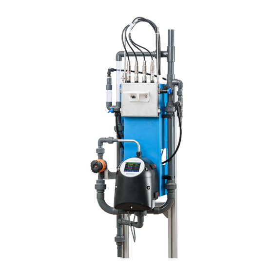
Instrument overview Instruction Manual AquaMaster Instrument overview Overview of AquaMaster with AquaScat 2 Figure 1: Instrument overview of AquaMaster with AquaScat 2 Photometer AquaScat 2 WTM / Flow Regulator valve for photometer WTM A / HT ... -
Page 12: Designation Of The Photometer
Instruction Manual AquaMaster Instrument overview Designation of the photometer The photometer is fitted with the following rating plate: Figure 2: Rating plate on AquaScat 2 WTM A Manufacturer Country of origin Product name Serial number ... -
Page 13: Identification Of The Connection Box
Instrument overview Instruction Manual AquaMaster Identification of the connection box The rating plate below is located on the connection box: Figure 3: AquaMaster rating plate, connection box Manufacturer Country of origin Product name Serial number ... -
Page 14: Scope Of Supply And Accessory Parts
Instruction Manual AquaMaster Instrument overview Scope of supply and accessory parts Standard scope of supply for AquaMaster 119490/1/2: PCS. ART. NO. NAME VIEW VARIANT 119490/1/2 AquaMaster com- plete with tubing, holder and meas- uring cell block. For 119490 Photometer AquaScat 2 WTM/... - Page 15 Instrument overview Instruction Manual AquaMaster PCS. ART. NO. NAME VIEW VARIANT Instruction Manual German English French Reference Hand- German book English Brief Instruction German English French Optional accessory parts: PCS. ART. NO. NAME VIEW VARIANT 119423 One deaeration tube optional...
- Page 16 Instruction Manual AquaMaster Instrument overview PCS. ART. NO. NAME VIEW VARIANT 119081 Ethernet cable IP66 (for fixed installa- tion) 119498 Conductivity Conducell 4USF sensor Arc 120 Sensor for measur- ing conductivity. 119509 Conductivity cali- bration standard 147 μ/cm, 500 ml...
-
Page 17: Aquamaster Technical Data
55 x 115 x 40 cm (B x H x T) Service voltage 100 .. 240 VAC, 47 .. 63 Hz or 18 .. 30 VDC Power consumption 10W AquaMaster + 4 Sensors 25W AquaMaster + 4 Sensors + optional Photometer Weight ca.16 kg Protection class IP 54... - Page 18 Instruction Manual AquaMaster Instrument overview Technical data for the AquaScat 2 WTM: DATA VALUES Measuring principle Scattered light measurement Measurement span 0 .. 4000 FNU Wavelength 880 nm, compliant with DIN EN ISO 7027 Radiation class LED device of Class 1 according to EN 60825-1 Measuring angle 90°...
- Page 19 Instrument overview Instruction Manual AquaMaster Technical data for the AquaScat 2 HT (remaining data identical to AquaScat 2 WTM): DATA VALUES Resolution 0.1 FNU Reproducibility 0 .. 10 FNU: ±0.1 FNU, or ±1% full scale at flow rate 2.5 .. 7 l/min (at flow rate 1.3 ..
- Page 20 Instruction Manual AquaMaster Instrument overview Conductivity sensor (Conducell 4USF Arc 120): DATA VALUES Sensor type Conductivity Measuring principle 4-pin measurement Measuring values Conductivity: µS/cm, mS/cm Temperature: °C, °K, °F Measuring range 1 .. 300,000 µS/cm Operating temperature -20 .. 130 °C Accuracy ±...
- Page 21 Instrument overview Instruction Manual AquaMaster Sensor Redox/ORP (Polilyte Plus ORP Arc 120): DATA VALUES Sensor type Redox/ORP Measuring principle Potential measurement Measuring values ORP: mV Temperature: °C, °K, °F Measuring range -1500 .. 1500 mV Operating temperature 0 .. 130 °C...
-
Page 22: General Safety Points
Instruction Manual AquaMaster General safety points General safety points Dangers when using properly Damage to instrument or cabling. Touching damaged cables may lead to electrical shocks resulting in death. The instrument may be operated only when the cables are undamaged. -
Page 23: Preventing Undesirable Online Access Attempts
Preventing undesirable online access attempts SIGRIST instruments are equipped with an integrated web user interface and Modbus TCP interface, thus offering state-of-the-art administration and control possibilities. However, if these are connected directly to the Internet, then any In- ternet user can in principle access your instrument and change the configuration. -
Page 24: Residual Risk
Instruction Manual AquaMaster General safety points Residual risk According to the risk assessment of the applied safety directive DIN EN 61010-1, there remains the risk of the displayed measuring values being incorrect. This risk can be reduced with the following measures: ... -
Page 25: Mounting And Installation
Mounting and installation Instruction Manual AquaMaster Mounting and installation Safety pointers for electrical connection Connecting the service voltage. Improper connection of the electrical service voltage can be life-threatening. The system may also be damaged. Local regulations for electrical connections must be observed at all times. -
Page 26: Mount Base Plate
Instruction Manual AquaMaster Mounting and installation Mount base plate When mounting the base plate, refer to the AQUAMASTER/1-MB dimension drawing and the AQUAMASTER/6-MB drill plan. Grip the base plate only on the blue sheet. WORKSTEP ADDITIONAL INFO / IMAGES Drill four holes in the wall for the threaded an- chor according to the drill plan. -
Page 27: Connecting The Connection Box
Mounting and installation Instruction Manual AquaMaster Connecting the connection box The connection cables between the connection box, photometer and external connections should be long enough so that there is sufficient freedom of movement when carrying out servicing duties (e.g. in order to fasten the photometer onto the docking station). - Page 28 Instruction Manual AquaMaster Mounting and installation WORKSTEP ADDITIONAL INFO / IMAGES Sensors purchased afterwards are connected to the free terminals marked with Sensor (Sensor 1 to Sensor 5). The order is not im- portant here. The connection of the sensors is described in the following sections: ...
-
Page 29: Position Of The Connection Box
Mounting and installation Instruction Manual AquaMaster Position of the connection box The connection box is positioned with the screwed cable glands to the right between wall and base plate on the contact surface. The connection cables to the sensors are routed upward. The connection cable to the photo- meter is routed downward. -
Page 30: Fasten Photometer To Base Plate
Instruction Manual AquaMaster Mounting and installation Fasten photometer to base plate WORKSTEP ADDITIONAL INFO / IMAGES Fasten the photometer mounting bracket to the base plate. Make sure that the two posi- tioning pins (circles) are inserted into the holes on the mounting bracket of the photometer. - Page 31 Mounting and installation Instruction Manual AquaMaster WORKSTEP ADDITIONAL INFO / IMAGES 4.2: Ensure that the inlet tube projects 5 mm out of the holder. 4.3: Fasten the inlet tube first to the PVC union piece (X) and then to the conduit gland on the measuring cell unit of the photometer (Y).
-
Page 32: Connecting The Electrical Connections
Instruction Manual AquaMaster Mounting and installation Connecting the electrical connections Life-threatening voltage inside the instrument: The system has no mains switch, hence the system is charged with voltage immediately af- ter being electrically connected. DANGER! Cable lengths should be long enough such that during servicing duty there is sufficient room for movement of the photometer and its peripherals (e.g. - Page 33 Mounting and installation Instruction Manual AquaMaster WORKSTEP ADDITIONAL INFO / IMAGES 2.2: Connect the cable as follows to the termi- nals of the AQ2Basi print. Pos. 1) Connection to the connection box Terminals Name Cable color Brown Green White Yellow Pos.
- Page 34 Instruction Manual AquaMaster Mounting and installation WORKSTEP ADDITIONAL INFO / IMAGES Connect the digital inputs and outputs ac- Reference Manual cording to the following table: Outputs 3 .. 7 on the I/O module Terminals Name Inputs 2 .. 5 on the I/O module...
-
Page 35: Mount Sensors Before Commissioning
Mounting and installation Instruction Manual AquaMaster Mount sensors before commissioning Damage to the sensors due to improper handling. pH sensors and Redox/ORP sensors must be carefully handled. pH sensors have a sensitive glass membrane; redox sensors have a very fine platinum wire at the measuring tip. These sensors can be damaged by carelessly touching the measuring tip, by improper cleaning. - Page 36 Instruction Manual AquaMaster Mounting and installation WORKSTEP ADDITIONAL INFO / IMAGES With the name to the front, insert the sensor vertically into the measuring cell block and push in with moderate pressure. If pH or Redox/ORP sensors are used, remove the lock cap beforehand.
- Page 37 Mounting and installation Instruction Manual AquaMaster WORKSTEP ADDITIONAL INFO / IMAGES Fold up measuring cell block cover. If the locking device has not been pushed onto the measuring cell block or not been properly pushed, the cover cannot be closed.
-
Page 38: Connect Water
Instruction Manual AquaMaster Mounting and installation Connect water WORKSTEP ADDITIONAL INFO / IMAGES There are two connection types: ¾" (X) and 1 ¼" (Y) thread 16 mm (X) and 25 mm (Y) hose nipple To fasten the hoses, first remove the hose nipples (X and Y) from the line;... -
Page 39: Mounting The Optional Flow Meter
Mounting and installation Instruction Manual AquaMaster 4.10 Mounting the optional flow meter SIGRIST recommends installing a simple flow meter to regularly check the sample. Note the following points when mounting the flow meter: Mount the flow meter between the main inlet of the sample and the photometer inlet. -
Page 40: Commissioning
Instruction Manual AquaMaster Commissioning Commissioning The initial start-up of the web user interface via the Ethernet interface is described in the Reference Manual. If malfunctions occur, consult the Section 9. Proceed with the initial start-up in accordance with the following table:... - Page 41 Commissioning Instruction Manual AquaMaster WORKSTEP ADDITIONAL INFO / IMAGES Establish and adjust sample feeding to meas- uring cell block 4.1: Open inlet regulator valve (B) to the measur- ing cell block all the way. 4.2: Open outlet regulator valve of the measuring cell block (D) until water continually flows through the sight glass (E).
- Page 42 Instruction Manual AquaMaster Commissioning WORKSTEP ADDITIONAL INFO / IMAGES Set operating language. Section 7.1 Set current outputs if required. Section 7.2 Set limits. Section 7.3 Enter access code. Section 7.9 Copy the configured data to the microSD card. Section 7.10...
-
Page 43: Operation
Operation Instruction Manual AquaMaster Operation Operation basics In this document we describe the practical examples only for the first steps of the menu con- figuration. All other setting options are described in the Reference Handbook. Operation us- ing the web user interface is described in detail in the Reference Manual. -
Page 44: Control Elements In Measuring Operation
Instruction Manual AquaMaster Operation Control elements in measuring operation Figure 5: Control elements in measuring operation Menu button Valu button Call up the menu structure. Numerical representation of the meas- Section 6.3 uring values. Section 6.4 ... -
Page 45: Info Button
Operation Instruction Manual AquaMaster Info button When you press the Info button, a general overview of the instrument settings appears. These are described below: 6.5.1 Page 1, Info button Figure 6: Info display Information about the current out- Status of the inputs ... -
Page 46: Info Button
Instruction Manual AquaMaster Operation 6.5.2 Page 2, Info button Figure 7: Info screen, page 2 Contact information Display of up to 5 pending fault mes- sages 12745E/4... -
Page 47: Info Button
Operation Instruction Manual AquaMaster 6.5.3 Page 3, Info button The state of all connected sensors is displayed here. Figure 8: Info screen, page 3 Sensor name Serial numbers of the corresponding sensor Fault message... -
Page 48: Diag Button
Instruction Manual AquaMaster Operation Diag button When you press the Diag button, a diagram appears which graphically shows the measuring values over a certain period of time. Figure9: Graphic representation of the measuring values Graphic representation of the... -
Page 49: Functions Of The Log Screen (Log Button)
Operation Instruction Manual AquaMaster Functions of the log screen (Log button) The screen logger works independently of the data logger, which is set in the Logger menu and writes to the microSD card. The screen logger records the data of the last 32 days in one minute intervals. The data can be called up from the Log menu. -
Page 50: Displays In Measuring Operation
Instruction Manual AquaMaster Operation Displays in measuring operation Figure 11: Displays in measuring operation Measuring value(s) Status line For values which are greater than In normal operation, the status line is the maximum measuring range, no green and shows the date and time. -
Page 51: Activating And Deactivating The Screen Lock
Operation Instruction Manual AquaMaster Activating and deactivating the screen lock MANIPULATION Press the lock icon top left. Within one second press the key bottom at the outside right. Depending on the initial state, the lock icon changes as follows: Display unlocked... -
Page 52: Switching To Service Operation
Instruction Manual AquaMaster Operation 6.10 Switching to service operation The system is configured in service operation. The measuring procedure is interrupted and the main menus appear on the display. Proceed as follows to access service operation: MANIPULATION ADDITIONAL INFO / IMAGES Press the Menu button. -
Page 53: Control Components In Service Mode
Page number / total number of pages Main menus Next page All of the AquaMaster functions are configured in the Local …… menu. Depending on the integrated sen- sors, the S 1 .. 8 (sensor 1 .. 8) menus appear here. -
Page 54: Numerical Entry
Instruction Manual AquaMaster Operation 6.11.2 Numerical entry The following screen is for entering numbers and data: Figure 13: Numerical entry Parameter name Entered values Prefix: For entering very large or Numerical entry very small values. This can be done as follows: 1. -
Page 55: Single Selection Of Functions
Operation Instruction Manual AquaMaster 6.11.3 Single selection of functions The single selection is identifiable by the ESC button below right. The currently selected function is green. Use the Up/Down arrows to navigate the options in long lists. Use the ESC button to cancel the entry. -
Page 56: Settings
Instruction Manual AquaMaster Settings Settings Setting the operating language MANIPULATION ADDITIONAL INFO / IMAGES Press the Menu button. Set access code and confirm with OK. Factory setting is 0. Press the Local ……. button. Press the Configuration button to access lan- If the desired menu does not guage selection. -
Page 57: Set Current Outputs
Settings Instruction Manual AquaMaster Set current outputs MANIPULATION ADDITIONAL INFO / IMAGES Press the Menu button. Set access code and confirm with OK. Factory setting is 0. Press the Local ……. button. Press the Curr. outputs button. If the desired menu does not appear, press the arrow key bottom right. -
Page 58: Set Limits
Instruction Manual AquaMaster Settings Set limits MANIPULATION ADDITIONAL INFO / IMAGES Press the Menu button. Set access code and confirm with OK. Factory setting is 0. Press the Local ……. button. If the desired menu does not appear, press the arrow key bottom right. -
Page 59: Upper And Lower Threshold Value Of A Limit
Settings Instruction Manual AquaMaster Upper and lower threshold value of a limit A maximum of eight limits with upper and lower threshold values can be programmed. If the operating mode is set to Exceeded, then while the upper threshold value is... -
Page 60: Set Outputs
Instruction Manual AquaMaster Settings Set outputs MANIPULATION ADDITIONAL INFO / IMAGES Press the Menu button. Set access code and confirm with OK. Factory setting is 0. Press the Local ……. button. Press the Inp./outputs button. If the desired menu does not appear, press the arrow key bottom right. -
Page 61: Setting The Measuring Channels And The Display
Settings Instruction Manual AquaMaster Setting the measuring channels and the display Setting of which channel should display the connected sensors MANIPULATION ADDITIONAL INFO / IMAGES Press the Menu button. Set the access code and confirm with OK. Factory setting is 0. - Page 62 Instruction Manual AquaMaster Settings MANIPULATION ADDITIONAL INFO / IMAGES Select the source of the measuring channel from the Source menu item. This name is dis- played to simplify identification of the measu- ring channel. The source defined under Channel 1 is displayed in the operation display at the top.
-
Page 63: Setting The Date And Time
Settings Instruction Manual AquaMaster Setting the date and time MANIPULATION ADDITIONAL INFO / IMAGES Press the Menu button. Set access code and confirm with OK. Factory setting is 0. Press the Local ……. button. Press the Configuration button. If the desired menu does not appear, press the arrow key bottom right. -
Page 64: Setting Or Changing The Access Code
Enter the access code and confirm with OK. Press the Meas button. Instrument again in measuring op- eration. A forgotten access code can be cleared only by a SIGRIST service engineer. Enter your personal access code here: 12745E/4... -
Page 65: Back Up Configured Data
Settings Instruction Manual AquaMaster 7.10 Back up configured data These measures can be of use to the service engineers for service purposes. MANIPULATION ADDITIONAL INFO / IMAGES Press the Menu button. Set access code and confirm with OK. Factory setting is 0. -
Page 66: Servicing
Instruction Manual AquaMaster Servicing Servicing Servicing schedule for AquaMaster WHEN WHAT PURPOSE Every three Operator Cleaning, checking and, if Obligatory measure for main- months or as required, recalibration of taining measuring accuracy. needed the pH sensor. Section 8.1.4 Every three... -
Page 67: Introduction To Handling Of The Sensors
The calibration process is designed for use with Hamilton calibration solutions (500 ml con- tainer). Although it is possible to use other calibration solutions, SIGRIST-PHOTOMETER ex- pressly recommends using the Hamilton standards. The pH sensor is subject to two-point calibration. All other sensors are subject to single-point calibration. - Page 68 Instruction Manual AquaMaster Servicing 8.1.1.3 Cleaning the sensor tips Damage to the sensors due to improper cleaning. Improper handling of the sensors when cleaning and the use of excessively aggressive clean- ing agents can lead to damage to the sensors. Note the following when cleaning the sen-...
-
Page 69: Removing Sensors
Servicing Instruction Manual AquaMaster 8.1.2 Removing sensors WORKSTEP ADDITIONAL INFO / IMAGES Close the inlet flow regulator valve to the measuring cell block (X). Slightly lift measuring cell block cover and fold down. Move locking device away from the measuring cell block by pressing the guide rod. -
Page 70: Installing Sensors
Instruction Manual AquaMaster Servicing 8.1.3 Installing sensors WORKSTEP ADDITIONAL INFO / IMAGES Insert sensor in the desired measuring position on the measuring cell block. The position of the sensors is generally irrelevant. However, because of escaping electrolyte it is better to position the pH and Redox/ORP sensors to the right of the Con- ductivity sensor. -
Page 71: Clean And Calibrate Ph Sensor
Servicing Instruction Manual AquaMaster 8.1.4 Clean and calibrate pH sensor The pH sensor can be damaged through improper handling. The pH sensor can be damaged by carelessly touching the measuring tip or by using the wrong cleaning agent. For cleaning this sensor please consult Section 8.1.1. - Page 72 Instruction Manual AquaMaster Servicing WORKSTEP ADDITIONAL INFO / IMAGES 4.2: Submerge the pH sensor into the calibra- tion solution to the second notch. The sensor should be centered in the calibration beaker and is not permitted to contact the bottom of the calibration beaker.
- Page 73 Servicing Instruction Manual AquaMaster WORKSTEP ADDITIONAL INFO / IMAGES 5.3: Press the Initiate button. The recalibration begins. If the quality indication af- If the adjustment was successful, confirm with ter calibration is between 100 Adjustment OK. This completes the adjust- and 35, the age of the sensor is ment.
-
Page 74: Clean And Calibrate Conductivity Sensor
Instruction Manual AquaMaster Servicing 8.1.5 Clean and calibrate Conductivity sensor The Conductivity sensor can be damaged through improper handling. The Conductivity sensor can be damaged by carelessly touching the measuring tip or by us- ing the wrong cleaning agent. ... - Page 75 Servicing Instruction Manual AquaMaster WORKSTEP ADDITIONAL INFO / IMAGES 4.2: Submerge the Conductivity sensor into the calibration solution to the second notch. The sensor must be centered in the cal- ibration beaker and is not permitted to con- tact the bottom of the calibration beaker.
- Page 76 Instruction Manual AquaMaster Servicing WORKSTEP ADDITIONAL INFO / IMAGES 5.3: Press the Initiate button. The recalibration If the quality indication af- begins. ter calibration is between 100 If the adjustment was successful, confirm with and 35, the age of the sensor is Adjustment OK.
-
Page 77: Clean And Calibrate Redox/Orp Sensor
Servicing Instruction Manual AquaMaster 8.1.6 Clean and calibrate Redox/ORP sensor The Redox/ORP sensor can be damaged through improper handling. The Redox/ORP sensor can be damaged by carelessly touching the electrode or by using the wrong cleaning agent. For cleaning this sensor please consult Section 8.1.1. - Page 78 Instruction Manual AquaMaster Servicing WORKSTEP ADDITIONAL INFO / IMAGES 4.2: Submerge the Redox/ORP sensor into the calibration solution to the second notch. 5.1: Compare the Nom. val. (circle) with the value on the calibration solution. Pressing the Nom. val. button (circle) causes a numerical entry field to appear where the nominal value can be adjusted.
- Page 79 Servicing Instruction Manual AquaMaster WORKSTEP ADDITIONAL INFO / IMAGES 5.3: Press the Initiate button. The recalibration If the quality indication af- begins. ter calibration is between 100 If the adjustment was successful, confirm with and 35, the age of the sensor is Adjustment OK.
-
Page 80: Cleaning And Calibrating The Oxygen Sensor
Instruction Manual AquaMaster Servicing 8.1.7 Cleaning and calibrating the oxygen sensor The oxygen sensor can be damaged through improper handling. The oxygen sensor can be damaged by touching the electrode carelessly or by using incor- rect cleaning agents. See Section 8.1.1 for details on how to clean the sensor. -
Page 81: Replace Sensors Configured By Sigrist
Cause: Values not yet stable. Install the sensor in the measuring cell block according to Section 8.1.3. 8.1.8 Replace sensors configured by SIGRIST WORKSTEP ADDITIONAL INFO / IMAGES Remove old sensor from the measuring cell block in accordance with Section 8.1.2. -
Page 82: Installing An Unconfigured Sensor
Instruction Manual AquaMaster Servicing 8.1.9 Installing an unconfigured sensor This process is only applicable if a new sensor has not been ordered from SIGRIST- PHOTOMETER. WORKSTEP ADDITIONAL INFO / IMAGES In the Local …… menu, access the Digi. interf. submenu. - Page 83 Servicing Instruction Manual AquaMaster WORKSTEP ADDITIONAL INFO / IMAGES Select the Siginet menu and press start… un- der “Network scan”. A search is made for a few seconds and then a list appears with all found sensors. If not all sensors are displayed, then proceed as follows: 1.
-
Page 84: Clean The Measuring Cell Block
Instruction Manual AquaMaster Servicing 8.1.10 Clean the measuring cell block Figure 18: Instrument overview of AquaMaster Inlet flow regulator valve for meas- Sensor positioned on locking device uring cell block Outlet regulator valve for measur- Measuring cell block... -
Page 85: Cleaning The Tubing
Servicing Instruction Manual AquaMaster WORKSTEP ADDITIONAL INFO / IMAGES Close main water supply. Remove all sensors from the measuring cell block and position in the locking device (Figure 18, pos. 2). Submerge pH sensor and Conductivity sensor in container with water to protect them from drying out. -
Page 86: Servicing Schedule For Aquascat 2 Wtm/Wtm A/Ht
Instruction Manual AquaMaster Servicing Servicing schedule for AquaScat 2 WTM/WTM A/HT WHEN WHAT PURPOSE Monthly or as Operator Checking the flow rate Obligatory measure for main- needed and cleanliness. taining measuring accuracy. Section 8.2.2 Every three Operator Only for WTM / HT: Per-... -
Page 87: Fastening The Optics Unit To The Docking Station
Servicing Instruction Manual AquaMaster 8.2.1 Fastening the optics unit to the docking station Figure 19: Optics unit fastened to docking station Optics unit Docking station with knurled screw for fastening the optics unit Measuring cell component... - Page 88 Instruction Manual AquaMaster Servicing The optics unit is mounted on the docking station as follows: WORKSTEP ADDITIONAL INFO / IMAGES Open the mounting clips (circle in figure be- low) as follows: Use a little force to push the red fuse in the direction of the arrow (picture 1) and at the same time lift the mounting clip (picture 2).
-
Page 89: Checking The Flow Rate And Cleanliness
Servicing Instruction Manual AquaMaster 8.2.2 Checking the flow rate and cleanliness The following procedure describes how the flow rate is checked: WORKSTEP ADDITIONAL INFO / IMAGES Remove the optics unit of the photometer Section 8.2.1 and fasten onto the docking station. - Page 90 Instruction Manual AquaMaster Servicing WORKSTEP ADDITIONAL INFO / IMAGES Check the light trap in the measuring cell for residual water (circle). Remove any residues with a cloth. Check the shutter assembly for residual water (circle). Remove any residues with a cloth.
-
Page 91: Flow Rate Reduction
Servicing Instruction Manual AquaMaster 8.2.3 Flow rate reduction A reduction of the minimum flow rate from 2.5 l/min to 1.3 l/min is possible; however, note the following points: Reproducibility worsens (from ±1% at 2.5 l/min to ±3% at 1.3 l/min). -
Page 92: Manual Adjustment
Instruction Manual AquaMaster Servicing 8.2.4 Manual adjustment The following procedure describes how manual adjustment is made with an AquaScat 2 WTM / HT: WORKSTEP ADDITIONAL INFO / IMAGES Interrupt the sample supply to the photome- ter. Loosen the conduit gland (X) and remove the inlet pipe (Y). - Page 93 Servicing Instruction Manual AquaMaster WORKSTEP ADDITIONAL INFO / IMAGES Place the optics unit back on the measuring cell unit and lock with the four mounting clips. Pay attention to the guide pins (see pic- ture). Switch the photometer to service operation.
-
Page 94: Automatic Adjustment With Aquascat 2 Wtm A
Instruction Manual AquaMaster Servicing 8.2.5 Automatic adjustment with AquaScat 2 WTM A The automatic adjustment is possible only with instrument type AquaScat 2 WTM A. The automatic adjustment can also be set for time actuation in the Adjust interval menu. This is described in the Reference Manual. -
Page 95: Cleaning The Parts Which Come Into Contact With Water
Servicing Instruction Manual AquaMaster 8.2.6 Cleaning the parts which come into contact with water The following describes cleaning the parts of the photometer that come into contact with water: WORKSTEP ADDITIONAL INFO / IMAGES Interrupt the sample supply to the photome- Section 4.9... - Page 96 Instruction Manual AquaMaster Servicing WORKSTEP ADDITIONAL INFO / IMAGES Loosen the conduit gland (D) and pull off the outlet pipe (E) downward. Clean the removed parts or replace if necessa- When doing so, also inspect the gasket in the outlet cone (arrow).
- Page 97 Servicing Instruction Manual AquaMaster WORKSTEP ADDITIONAL INFO / IMAGES Fasten this unit by tightening the conduit gland. At position X, there should now be no space between the outlet cone and the conduit gland! Insert the inlet pipe (B) from above into the conduit gland (A) to the stop.
-
Page 98: Checking Soiling Of The Lenses And Cleaning The Optics
Instruction Manual AquaMaster Servicing 8.2.7 Checking soiling of the lenses and cleaning the optics Figure 20: AquaScat 2 WTM A optics unit in adjust- Figure 21: AquaScat 2 WTM/HT ment position Transmitter Head of the automatic checking unit ... - Page 99 Servicing Instruction Manual AquaMaster The following describes checking the lenses for soiling and cleaning the optics: WORKSTEP ADDITIONAL INFO / IMAGES 1.1: If an AquaScat 2 WTM / HT is present, carry out an adjustment as described in Sec- tion 8.2.5.
- Page 100 Instruction Manual AquaMaster Servicing WORKSTEP ADDITIONAL INFO / IMAGES Clean the lens of the receiver: If the difference in the current calibra- tion factor is not greater than 10% and there is no visible soiling apparent on the shutter assembly, then it can be assumed that the lens on the receiver is not soiled.
- Page 101 Servicing Instruction Manual AquaMaster WORKSTEP ADDITIONAL INFO / IMAGES Restore the service voltage to the photome- ter. On instruments without automatic adjust- ment, carry out a manual adjustment as de- scribed in Section 8.2.4. This servicing duty is then completed.
- Page 102 Instruction Manual AquaMaster Servicing WORKSTEP ADDITIONAL INFO / IMAGES 12.3: Put the head of the checking unit on the positioning pins (arrows) and then fasten with the two screws. Place the optics unit back on the measuring cell unit and lock with the four mounting clips.
-
Page 103: Replacing The Air Filter
Servicing Instruction Manual AquaMaster 8.2.8 Replacing the air filter The following describes the replacement of the air filter: WORKSTEP ADDITIONAL INFO / IMAGES Interrupt the sample supply to the photome- Section 5 ter. Interrupt the service voltage to the photome- Section 4.4... -
Page 104: Replacing The Battery
Instruction Manual AquaMaster Servicing 8.2.9 Replacing the battery Danger due to electrical shock that may result in serious bodily injury or death. External signal lines may carry life threatening voltage even if the voltage supply to the in- strument is disconnected. Before opening the instrument, make sure that no connected lines are charged with voltage. - Page 105 Servicing Instruction Manual AquaMaster WORKSTEP ADDITIONAL INFO / IMAGES Carefully mount the front cover and fasten with the five screws. Damage to the threaded inserts in the housing due to excessive tightening of the screws of the front cover: Use a hex key without a T-handle to tighten...
-
Page 106: Troubleshooting
Instruction Manual AquaMaster Troubleshooting Troubleshooting Pinpointing malfunctions DETECTABLE MALFUNCTION ACTION No reading Check whether the supply voltage is present. Error message in the display Analyze the error message. Section 9.3 to Section 9.5 The reading is wrong Ensure that the sample to be measured corresponds to the operating conditions. -
Page 107: Replacing The Fine-Wire Fuses
Troubleshooting Instruction Manual AquaMaster Replacing the fine-wire fuses The following describes the replacement of the fine-wire fuse on the AQ2Basi print: WORKSTEP ADDITIONAL INFO / IMAGES Interrupt the service voltage to the photo- Section 4.7 or meter. Loosen the five screws on the front cover with a 7 mm key and remove the front cover. -
Page 108: Warning Messages And Effect On Operation
Instruction Manual AquaMaster Troubleshooting Warning messages and effect on operation Warnings indicate an unusual state. WARNINGS If a warning occurs during operation, it has the follow- ing effects: The system continues to operate; however, the measuring results must be carefully evaluated. The cause of the warning message should be remedied at the next possible opportunity. -
Page 109: Fault Messages And Effect On Operation
Troubleshooting Instruction Manual AquaMaster WARNING DESCRIPTION POSSIBLE CAUSES INTERFACE A connection problem with Oxygen: mA value outside Hamilton sensor. range. Oxygen: ECS (Electrical connec- tion for this sensor) is outside range. HARDWARE Hardware problem with Ham- Supply voltage outside range. - Page 110 Instruction Manual AquaMaster Troubleshooting The following error messages can be displayed: ERROR MESSAGE DESCRIPTION POSSIBLE CAUSES V ANALOG One of the internal analogue Defect in the electronic system. Service technician voltages is outside the permit- ted range. ...
-
Page 111: Prioritized Fault Messages And Their Effect On Operation
Prioritized faults can be cleared only by a service engineer. Prio fault originating from the AquaMaster: A prio fault of the AquaMaster sets all measuring values to 0. All current outputs go to the programmed electri- cal current If fault. -
Page 112: Customer Service Information
If this is not known, SIGRIST-PHOTOMETER AG customer service in Switzerland would be glad to provide you with a contact address. A current list of all SIGRIST country representatives is available in the Internet at www.photometer.com. Please have the following information ready when you contact a SIGRIST service point or customer service: ... -
Page 113: Decommissioning/Storage
Decommissioning/storage Instruction Manual AquaMaster 11 Decommissioning/storage 11.1 Decommissioning The aim of decommissioning is to prepare the individual components of the system properly for storage. WORKSTEP ADDITIONAL INFO / IMAGES Interrupt the service voltage to the system. Interrupt main water supply. -
Page 114: Storage
Instruction Manual AquaMaster Decommissioning/storage 11.2 Storage There are no special requirements for storing the instruments. However, please note the following information: The system contains electronic components. Storage for such components must fulfill the usual conditions. It is important to note that the storage temperature must be be- tween -20 and +50℃... -
Page 115: Packaging/Transport/Returning
(Refer to repair form). DANGER! Detailed information about the samples must be received by SIGRIST-PHOTOMETER so that relevant precautionary measures can be taken when unpacking. The original packaging of the photometer and its peripheral devices should be used for packaging when possible. -
Page 116: Disposal
Instruction Manual AquaMaster Disposal 13 Disposal Disposal of the system and its peripheral devices is to be carried out in compliance with re- gional statutory regulations. The system has no environmentally damaging sources of radiation. The materials listed be- low should be disposed of or recycled as described in the following table:... -
Page 117: Spare Parts List
Spare parts list Instruction Manual AquaMaster 14 Spare parts list 14.1 Spare parts for the AquaMaster The parts mentioned in this documentation and their article numbers are listed in the follow- ing table: Article number Article name Remarks 119500 pH sensor, replacement... -
Page 118: Appendix
Instruction Manual AquaMaster Appendix 15 Appendix 12745E/4... - Page 119 Appendix Instruction Manual AquaMaster This pa ge is inte ntionally bla nk 12745E/4...
-
Page 120: Index
Instruction Manual AquaMaster Index 16 Index Access code, set ........... 64 General calibration ..........67 Adjust interval ............94 Adjustment, automatic ......... 94 Air filter..............98 Improper use ............9 Article numbers ..........117 Incorrect use ............9 Initial start-up ............40 Internet ............. - Page 121 User requirements ..........8 Sensors, remove ........... 69 Service center ............. 112 Service operation ..........52 Servicing duties, AquaMaster ....... 66 Wall holder, mounting ........26 Servicing duties, AquaScat 2 ........ 86 Warning symbols on the instrument ....24 Setting the measuring channels ......61 Warnings ............
- Page 122 SIGRIST-PHOTOMETER AG Tel. +41 41 624 54 54 Hofurlistrasse 1 +41 41 624 54 55 CH-6373 Ennetbürgen info@photometer.com Switzerland www.photometer.com...
Need help?
Do you have a question about the AquaMaster and is the answer not in the manual?
Questions and answers