Table of Contents
Advertisement
Quick Links
INSTRUCTION MANUAL
Absorption Measuring
Document Number: 10210E
ColorPlus Ex
SIGRIST
Instrument
with SIREL SMD / SIREL Ex
SIGRIST-PHOTOMETER AG
Hofurlistrasse 1
CH-6373 Ennetbürgen
Switzerland
Version: 5
Phone:
+41 (0)41 624 54 54
Fax:
+41 (0)41 624 54 55
E-mail:
info@photometer.com
Internet:
www.photometer.com
Valid from: 2019-09-01
Advertisement
Table of Contents

Subscribe to Our Youtube Channel
Related Manuals for SIGRIST ColorPlus Ex


Summary of Contents for SIGRIST ColorPlus Ex
- Page 1 INSTRUCTION MANUAL ColorPlus Ex SIGRIST Absorption Measuring Instrument with SIREL SMD / SIREL Ex SIGRIST-PHOTOMETER AG Phone: +41 (0)41 624 54 54 Hofurlistrasse 1 Fax: +41 (0)41 624 54 55 CH-6373 Ennetbürgen E-mail: info@photometer.com Switzerland Internet: www.photometer.com Document Number: 10210E...
- Page 2 © Sigrist-Gruppe, Subject to change without notice 09/19...
-
Page 3: Table Of Contents
Instruction Manual ColorPlus Ex Contents 1 Instrument Description ............... 5 1.1 General view of a bypass measuring setup ........5 1.2 General view of an inline measuring setup........5 1.3 Scope of supply and accessories ........... 6 1.4 Purpose and conformity..............7 1.5 Marking of the Product .............. - Page 4 Instruction Manual ColorPlus Ex 6.1 Pinpointing the cause of a malfunction ......... 52 6.2 Fault messages ................. 52 6.3 Warnings ................. 54 6.4 Information ................55 6.5 Customer service information ............. 55 7 Taking Out of Service/storage ............57 8 Packing/Transport ................58 9 Disposal ..................
- Page 5 Instruction Manual ColorPlus Ex Foreword This Instruction Manual describes the basic functions for operating the ColorPlus Ex. It is addressed to all persons who are responsible for operation of the instrument. Operate the instrument only after having familiarized yourself with the contents of this Instruction Manual.
- Page 6 Instruction Manual ColorPlus Ex 10210E/5...
-
Page 7: Instrument Description
Instruction Manual ColorPlus Ex 1 Instrument Description General view of a bypass measuring setup Pos. Name Control unit Example with SIREL SMD Transmitter Flow cell Receiver Photometer Ex-zone Transmitter-receiver connecting cable Photometer-SIREL Figure 1: General view of a bypass measuring setup... -
Page 8: Scope Of Supply And Accessories
Instruction Manual ColorPlus Ex Scope of supply and accessories Standard scope Units Name Alternatives Optional of supply Photometer ColorPlus Ex for bypass, for Varivent® installation (inline) or in user-specific version Control unit SIREL, SIREL robust with 85..264 VAC, 24 VDC SITRA/SIBUS... -
Page 9: Purpose And Conformity
Instruction Manual ColorPlus Ex Purpose and conformity Use of the photometer for purposes other than that for which it was designed can produce incorrect measuring results, possibly with consequential damage to the process and damage to the photometer itself. Installation and operation of the control unit and any supplementary... -
Page 10: Marking Of The Product
Figure 3: Plates for the serial number and the Figure 4: Photometer rating plate. electrical connection figures. X: rating plate of the manufacturer ( SIREL Ex Instruction Manual) Figure 5: Position of the SIGRIST rating plate on the SIREL Ex 10210E/5... - Page 11 Instruction Manual ColorPlus Ex The photometer rating plate provides the following information: Pos. Name Manufacturer Instrument type Serial number Conformity data Ex protection type Temperature classes Ambient temperature EC Type Examination Certificate Warning Figure 6: Information on identification plate You can also consult the photometer’s serial number in the menu * SYSTEM INFO * (...
-
Page 12: Technical Data
Instruction Manual ColorPlus Ex Technical data Absorption Measuring principle: Absorption at 1 .. 3 different wavelengths: 254, 313 measurement or 365 .. 700nm Measuring span: 0 .. 0.05 E to 0 .. 3 E Resolution: 0.001 E Reproducibility: 1 % Ambient temperature: -20 .. - Page 13 Instruction Manual ColorPlus Ex Operating voltage: 24 V DC (from control unit) Photometer Interfaces: Modbus / with optional bus coupler Profibus DP Flow cell - bypass flow cell Stainless steel 1.4435, connections G ¼” female thread - inline flow cell Varivent®...
- Page 14 Instruction Manual ColorPlus Ex SIREL Ex Service voltage 85 .. 264 V, 47 .. 63 Hz Mains switch None Dimensions 320 mm x 645 mm x 203 mm Detailed dimension drawing see Section 11 Weight Approx. 25 kg Protection type...
-
Page 15: Safety Rules
Instruction Manual ColorPlus Ex 2 Safety Rules The symbols used in this Manual and on the photometer draw attention to the following safety steps or precautions: WARNING: EXPLOSION HAZARD (CAN BE FATAL)! Thoughtless action can result in explosions! Before undertaking maintenance... -
Page 16: Installation/Start-Up
Instruction Manual ColorPlus Ex 3 Installation/start-up Photometer installation for the bypass version The photometer must be installed in the horizontal position. To make it possible to vent the flow cell properly, make sure the medium outlet is on top. Action... -
Page 17: Photometer Installation In Inline Housing
The groove (A) on the transmitter and receiver must be installed pointing upward! Be sure to install the ColorPlus Ex so the transmitter and receiver are positioned horizontally opposite each other! Only install a housing that makes this possible! The photometer must be installed in the pipe at least 2 m away from sight ... -
Page 18: Sectional View Of Measuring Setup
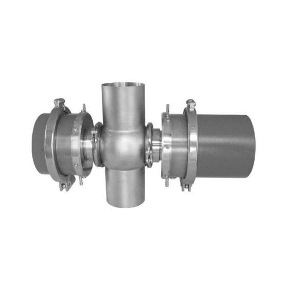
Instruction Manual ColorPlus Ex 3.2.1 Sectional view of measuring setup For detailed dimension drawings of ColorPlus Ex, refer to Section 11. The inline housing is flanged into the pipe. Pos. Name Receiver Adapter ring Flow cell window Hinged ring Transmitter... -
Page 19: Installation With Shortened Path Length
Instruction Manual ColorPlus Ex 3.2.2 Installation with shortened path length The ColorPlus Ex is delivered for installation in an inline housing with a shortened path length (7) on both sides. The path length shorteners (OPL bits) with flow cell window (3), matching leakage protector (8) and adapter ring (2) are installed at the factory to meet the customer’s requirements. -
Page 20: Installation Of The Cooling System (Option)
Instruction Manual ColorPlus Ex Installation of the cooling system (option) Pos. Name Direction of flow of the cooling water Cooling water outlet transmitter Transmitter Cooling water inlet transmitter Inlet tube Connecting tube between transmitter and receiver Cooling water inlet receiver... -
Page 21: Installation Of The Control Units Sirel Smd
Instruction Manual ColorPlus Ex Installation of the control units SIREL SMD Do not install or operate the control unit or any supplementary components in areas at risk of explosion (CAN BE FATAL)! The control units can be mounted right on the wall, on a mounting frame or on Mounting SIREL a stand. - Page 22 Instruction Manual ColorPlus Ex The control unit can be placed in larger distance to the Photomter by using a Distances longer customized cable length: than 5 m – variant 2 Pos. Name Photometer SIREL control unit Non Ex-zone Partition Ex-zone...
-
Page 23: Installation Of The Sirel Ex Control Unit
Max. length y [m] 0.14 0.25 0.34 0.75 standard cable The maximum distance (z) between SITRA and control unit depends on the cable cross-section used: Cable cross-section [mm2] ColorPlus Ex UV + VIS Max. length z [m] 0.14 0.25 0.34 1161 1200 0.75... -
Page 24: Electrical Connections
Instruction Manual ColorPlus Ex Electrical connections 3.7.1 Voltage equalizing cable connection on the flow cell housing It is absolutely necessary for the flow cell housing to be connected to the voltage equalizing cable! The following rules apply for the different versions: In the case of the inline version, the piping system including the Varivent®... -
Page 25: Opening The Sirel Smd
Instruction Manual ColorPlus Ex 3.7.3 Opening the SIREL SMD All electrical connections are made with spring-loaded terminals inside the Opening the control unit control unit. To open the control unit, unscrew the four screws underneath the side covers ( Figure 15). -
Page 26: Establish Sirel Smd/Ex Electrical Connections
Instruction Manual ColorPlus Ex 3.7.5 Establish SIREL SMD/Ex electrical connections For information about control signals, please refer to Section 2 in the Reference Handbook. The terminals of the SIREL Ex are located in the lower part of the housing (Figure 16). The housing must be open in order to connect the electrical connections ... - Page 27 Instruction Manual ColorPlus Ex Make up the electrical connections in the following order: Terminals Used for Remarks Connection to photometer green Connection brown white yellow 4 - 5 - 6 Relay output 1 The relay outputs are freely configurable 7 - 8 - 9 Relay output 2 (...
-
Page 28: Initial Start-Up
Instruction Manual ColorPlus Ex Initial start-up Carry out the initial start-up according to the following table. In the event of malfunctions, consult Section 6. Action Remarks Make sure the photometer and Section 3 control unit are correctly mounted and connected. -
Page 29: Operation
Instruction Manual ColorPlus Ex 4 Operation Operating elements and display SIREL SMD SIREL Pos. Name Channel number and reading Measuring value Unit set (e.g. E/m or %T ( Reference Handbook) Arrow key up Arrow key right Arrow key down Arrow key... - Page 30 Instruction Manual ColorPlus Ex SIREL Robust (cover removed) Figure 20: Operating elements of SIREL robust Key functions: Pos. Symbols Key functions Switch between menu lines 1, 2 / Change numbers in the editing mode (see below) Switch between the functions of a menu line 4, 5 /...
-
Page 31: Control Components And Display Of The Sirel Ex
Instruction Manual ColorPlus Ex 4.1.1 Control components and display of the SIREL Ex The operator prompting of the SIREL Ex is identical to that of the SIREL SMD. Only the integrated keyboard and the housing differentiate the SIREL Ex from the SIREL SMD. -
Page 32: Normal Operation (Operating Mode)
Instruction Manual ColorPlus Ex Normal operation (operating mode) When the instrument is switched on, ColorPlus Ex first checks which control units are connected to it. Then it switches automatically to normal operation. If several SIRELs are connected to the photometer, all of the control units must... -
Page 33: Service Mode
Instruction Manual ColorPlus Ex Service mode The photometer can be configured in the service mode. Measuring is interrupted. The following menu control appears on the display: Action Display (example) Remarks Access code If no personal access > 000000 <... -
Page 34: Set The Measuring Range
Instruction Manual ColorPlus Ex Set the measuring range Action Display (example) Remarks Activate service mode. * 100% ADJUST. * Section 4.3 * MEAS.RANGE * LIMITS > Meas.range < Set the range for X... output signals 1 + 2. -
Page 35: Configure The Channels
Instruction Manual ColorPlus Ex Configure the channels Depending on the instrument type, the instrument can have 1..3 channels (wavelengths) and two calculation channels (math channels). All of the channels are configured at the factory to suit the user’s needs. No setting is required upon installation. -
Page 36: Set The Limits
Instruction Manual ColorPlus Ex Action Display (example) Remarks Assign functions: Limit 2 Relay 2 >li AL se wa in< / exceeded Function al = Alarm (fault on/off has occurred) / Change func- se = Instrument in tion service mode wa =... - Page 37 Instruction Manual ColorPlus Ex Action Display (example) Remarks Switch to the service Section 4.3 * 100% ADJUST. * mode. * MEAS.RANGE * LIMITS LI1 = Limit 1 > LI1 source < Channel 1 LI2 = Limit 2...
-
Page 38: Set The Access Code
Instruction Manual ColorPlus Ex Set the access code You can use a self-defined access code to protect the ColorPlus Ex settings against tampering. Action Display (example) Remarks Activate service mode. * 100% ADJUST. * Section 4.3 3 x ... -
Page 39: Servicing
Instruction Manual ColorPlus Ex 5 Servicing Do not open the photometer before the power supply to the control unit has been disconnected and then a waiting time of ten minutes has passed to allow the light source to cool down sufficiently (EXPLOSION HAZARD)! The electric power supplied to the UV light source CAN CAUSE FATAL ... -
Page 40: 100% Adjustment Of The Photometer
Instruction Manual ColorPlus Ex 100% adjustment of the photometer Recalibration of the photometer can change the readings slightly from the previous ones, because the instrument is reset to a reference standard (e.g. distilled water)! Before the 100% adjustment is started, the photometer must have reached the operating temperature (UV >... -
Page 41: Functional Check With Reference Glass
Instruction Manual ColorPlus Ex Functional check with reference glass Action Remarks Fill the flow cell with zero medium. Do not empty the flow cell again until you have taken the reading (point 10)! Do not open the photometer before the... - Page 42 Instruction Manual ColorPlus Ex Action Remarks Press key . Depending on the configuration, between one and three transmission values will appear in the top line. Take the reading(s) and note it down. Compare the measured value with the value noted down from inside the enclosure.
-
Page 43: Replacement Of The Desiccant In The Sensor Head
Instruction Manual ColorPlus Ex Replacement of the desiccant in the sensor head Action Remarks Do not open the photometer before the power supply to the control unit has been disconnected and then a waiting time of ten minutes has passed to allow the light source... - Page 44 Clean window (A) with a cotton rag. Reassemble the instrument in reverse order and restart it. If you have to replace the desiccant frequently, you should have a SIGRIST service technician check the tightness of the Ex enclosure. 10210E/5...
-
Page 45: Replacement Of The Desiccant In The Transmitter
Instruction Manual ColorPlus Ex Replacement of the desiccant in the transmitter The electric power supplied to the UV light source CAN CAUSE FATAL INJURY! So for all instruments with a UV light source, it is absolutely necessary to disconnect the power supply before opening the enclosure! The UV radiation from the bulb can damage your eyes! ... -
Page 46: Replacement Of The Desiccant In The Receiver
Instruction Manual ColorPlus Ex Replacement of the desiccant in the receiver Action Remarks Do not open the photometer before the power supply to the control unit has been disconnected and then a waiting time of ten minutes has passed to allow the light source... -
Page 47: Cleaning/Replacement Of The Flow Cell Windows In Bypass Flow Cells
Instruction Manual ColorPlus Ex Cleaning/replacement of the flow cell windows in bypass flow cells Action Remarks Do not open the photometer before the power supply to the control unit has been disconnected and then a waiting time of ten minutes has passed to allow the light source... -
Page 48: Cleaning/Replacement Of The Flow Cell Windows On The Varivent
Instruction Manual ColorPlus Ex Action Remarks Now you can remove the threaded ring, thrust ring, seal and flow cell window. Clean the flow cell window with a suitable cleaning agent. Take care not to dirty it again during reinstallation. If necessary, replace the flow cell window and seal. - Page 49 Instruction Manual ColorPlus Ex Action Remarks Remove the transmitter / receiver, including the OPL bit from the inline flow cell. Loosen the six screws (A) on the adapter ring of the transmitter / receiver. Withdraw the adapter ring (including the screwed-on OPL bit) from the transmitter / receiver.
- Page 50 Instruction Manual ColorPlus Ex Action Remarks Take the thrust ring and the flow cell window with seal out of the OPL bit. Remove the seal from the flow cell window and clean the window with a cleaning paper or rag, possibly using warm soapy water.
- Page 51 Instruction Manual ColorPlus Ex Action Remarks Clean all contact surfaces on the inline housing. Insert the transmitter / receiver with screwed- on adapter ring and OPL bit back into the inline housing. Make sure the groove (A) of the transmitter / receiver is pointing upward after...
-
Page 52: Replacement Of The Uv Light Source
Instruction Manual ColorPlus Ex Replacement of the UV light source The electric power supplied to the UV light source CAN CAUSE FATAL INJURY! So for all instruments with a UV light source, it is absolutely necessary to disconnect the power supply before opening the enclosure! The UV radiation from the bulb can damage your eyes! ... - Page 53 Instruction Manual ColorPlus Ex Action Remarks Pull the UV light source’s plug (A) out of the circuit board. Loosen the fastening screw (B) of the UV light source. Don’t touch the glass of the UV bulb with your fingers! Clean it with alcohol before installation! Withdraw the UV bulb (C) from its base.
-
Page 54: Troubleshooting
Table 5: Pinpointing a malfunction Fault messages In the ColorPlus Ex, readings are measured, inputs monitored and outputs updated continuously. If the ColorPlus Ex detects a fault during this process, a fault message will be emitted and displayed on the control unit. 10210E/5... - Page 55 Instruction Manual ColorPlus Ex The ColorPlus Ex can detect the following faults: Message Signifies Possible causes connection The control unit has no Connection to lost ... connection to the photometer. photometer interrupted Defective electronics ( Service technician) Fault...
-
Page 56: Warnings
Warnings Temperature, leakage and degree of contamination are monitored continuously in the ColorPlus Ex. If this monitoring shows that a limit has been exceeded, a warning is emitted and displayed on the control unit. These warnings can be detected by ColorPlus Ex:... -
Page 57: Information
Service of SIGRIST-PHOTOMETER AG in Switzerland will gladly give you the relevant contact address. You will also find the current list of all SIGRIST country representatives in the internet at www.photometer.com. When you contact a SIGRIST Service Office or Customer Service, please make sure you have the following information at hand: ... - Page 58 Instruction Manual ColorPlus Ex If you have problems with the reading, please have the following additional information at hand. It can be found in the menus for the sections Info, Adjustment, Compensation and Calibration: Name Option Value System information Section 1 Instr.
-
Page 59: Taking Out Of Service/Storage
Instruction Manual ColorPlus Ex 7 Taking Out of Service/storage Do not open the photometer before the power supply to the control unit has been disconnected and then a waiting time of ten minutes has passed to allow the light source to cool down sufficiently (EXPLOSION HAZARD)! (Cooling down of the device to a safe temperature level and elimination of residual charges.) -
Page 60: Packing/Transport
Instruction Manual ColorPlus Ex 8 Packing/Transport Whenever possible, use the original packing materials when packing the photometer and its peripherals for shipment. If the materials are no longer available, observe these instructions: Prior to packing, close all openings with pressure-sensitive tape or plugs to prevent any packing materials from penetrating them. -
Page 61: Disposal
Instruction Manual ColorPlus Ex 9 Disposal This product falls in Category 9 "Monitoring and Control Instruments" of European Directive RL 2002/95/EC (RoHS). Disposal of the photometer and its peripheral devices must be carried out in accordance with the regional legal provisions! Neither the photometer nor the control unit contains any sources of pollutant radiation. -
Page 62: Spare Parts
112860 75 Shore 111391 Desiccant bag, 30g 115555 Desiccant ring to sensor head for ColorPlus Ex wit h two seals 106069 Tempax glass window for KPA0.5 44/35.5x4.75/2.25, Pos. 6a 106076 Suprasil window for KPA0.5 44/35.5x4.75/2.25 106072 Tempax glass window for KPA2 44/35.5x5.5/1.5, Pos. 6a 106079 Bypass flow cell window, UV version, path 2mm 107633 Measuring cell window for KPA &... -
Page 63: Appendix
Instruction Manual ColorPlus Ex 11 Appendix 10210E/5... - Page 64 Instruction Manual ColorPlus Ex 10210E/5...
-
Page 65: Index
Instruction Manual ColorPlus Ex 12 Index 100% adjustment ....38 limits, definition ....... 34 limits, settings ......35 LVD ......... 7 access code, setting ....36 accessories ....... 6 adjustment, 100% ....38 mains switch ......22 Article Numbers ....... 60 malfunctions ..... - Page 66 Instruction Manual ColorPlus Ex 10210E/5...
Need help?
Do you have a question about the ColorPlus Ex and is the answer not in the manual?
Questions and answers