
Related Manuals for SIGRIST ScrubberGuard


Summary of Contents for SIGRIST ScrubberGuard
- Page 1 Document number: 14830E Version: 1 Valid from: S/N 297000 / SW V129 INSTRUCTION MANUAL ScrubberGuard Monitoring of exhaust gas cleaning system wash water...
- Page 2 Copyright© SIGRIST-PHOTOMETER AG, subject to technical changes without notice 4/2019 SIGRIST-PHOTOMETER AG Tel. +41 41 624 54 54 Hofurlistrasse 1 +41 41 624 54 55 CH-6373 Ennetbürgen info@photometer.com Switzerland www.photometer.com...
-
Page 3: Table Of Contents
2.2.4 Designation of the OilGuard SG (A) ............17 Scope of supply and accessories..............18 2.3.1 Standard scope of supply for the ScrubberGuard ........18 2.3.2 Optional accessories for the ScrubberGuard ..........19 Technical data for the ScrubberGuard ............. 21 2.4.1... - Page 4 5.5.7 Connecting the Modbus TCP ..............42 Commissioning ......................43 Operation ........................46 Control elements of the ScrubberGuard on the cabinet ........46 Operation basics ..................... 47 Control elements in measuring operation ............48 Menu button ....................48 Valu button ....................48 Info button .....................
- Page 5 General handling of the pH sensor ............87 9.3.2 Cleaning and calibrating the pH sensor ............. 89 9.3.3 Replacing pH sensors that have been configured by SIGRIST ...... 91 9.3.4 Installing an unconfigured pH sensor ............91 Servicing duties on the photometers ............... 93 9.4.1...
-
Page 7: General User Information
Purpose of the Instruction Manual This Instruction Manual provides the user with helpful information about the entire life cycle of the ScrubberGuard and its peripheral devices. Before commissioning the instrument, you should be completely familiar with the Instruction Manual. Target group of the documentation The Instruction Manual is intended for all persons who are responsible for the operation and maintenance of the instrument. -
Page 8: Order Document
The most recent version of this document can be downloaded at www.photometer.com (first time registration required). It can also be ordered from a SIGRIST representative in your country ( Instruction Manual “Customer service information”). Proper use The ScrubberGuard has been developed for monitoring the scrubbing water in exhaust gas cleaning systems. -
Page 9: Removing The Casing From The Scrubberguard
Instruction Manual ScrubberGuard 1.12 Removing the casing from the ScrubberGuard Usually, the ScrubberGuard is equipped with a protective casing. In order to gain a better understanding of the inner workings of the ScrubberGuard, the system is shown without a casing throughout this document. The casing can be fitted and removed using a Torx screw- driver. -
Page 10: Dangers When Not Used Properly
The system is not properly mounted, set up or transported. The system is not installed and operated in accordance with the Instruction Manual. The system is operated with accessories which SIGRIST-PHOTOMETER AG has not ex- pressly recommended. Improper changes have been performed to the system. -
Page 11: Meaning Of The Safety Symbols
General user information Instruction Manual ScrubberGuard 1.14 Meaning of the safety symbols All danger symbols used in this document are explained below: Danger due to electrical shock that may result in serious bodily injury or death. Non-observance of this notice may lead to electrical shocks and death. -
Page 12: Meaning Of The Pictograms
1.15 Meaning of the pictograms All pictograms used in this document are explained below: Additional information about the current topic. Practical procedures when working with the ScrubberGuard. Manipulations on the touchscreen. The screenshot is an example and may differ from current device. -
Page 13: Instrument Overview
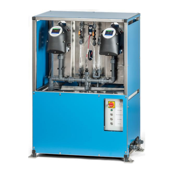
Instrument overview Instruction Manual ScrubberGuard Instrument overview Overview of the ScrubberGuard Figure 2: Overview of the ScrubberGuard OilGuard SG (optional) Flow meter AquaScat SG Deaeration tubes pH/temperature sensor Control cabinet (ScrubberController) A: Sample inlet... -
Page 14: Designation Of The Components
Instruction Manual ScrubberGuard Instrument overview Designation of the components 2.2.1 Designation of the ScrubberGuard The cabinet is fitted with the following rating plate: Figure 3: Designation of the ScrubberGuard Manufacturer Country of origin Product name Serial number ... -
Page 15: Designation Of The Scrubbercontroller
Instrument overview Instruction Manual ScrubberGuard 2.2.2 Designation of the ScrubberController The cabinet is fitted with the following rating plate for the ScrubberController: Figure 4: Designation of the ScrubberGuard Manufacturer Country of origin Product name Serial number ... -
Page 16: Designation Of The Aquascat Sg (A)
Instruction Manual ScrubberGuard Instrument overview 2.2.3 Designation of the AquaScat SG (A) The AquaScat SG (A) is fitted with the following rating plate: Figure 5: Rating plate on AquaScat SG (A) Manufacturer Country of origin Product name Serial number ... -
Page 17: Designation Of The Oilguard Sg (A)
Instrument overview Instruction Manual ScrubberGuard 2.2.4 Designation of the OilGuard SG (A) The OilGuard SG (A) is fitted with the following rating plate: Figure 6: Designation of the OilGuard SG (A) Manufacturer Country of origin Product name Serial number ... -
Page 18: Scope Of Supply And Accessories
Instruction Manual ScrubberGuard Instrument overview Scope of supply and accessories 2.3.1 Standard scope of supply for the ScrubberGuard PCS. ART. NO. NAME VIEW VARIANT 121290 ScrubberGuard A 230V/50 Hz 121435 ScrubberGuard 230V/50 Hz 121440 ScrubberGuard A 220/60 Hz 121445 ScrubberGuard... -
Page 19: Optional Accessories For The Scrubberguard
English 14831 Reference Manual German English 14832 Brief Instructions German French English 2.3.2 Optional accessories for the ScrubberGuard PCS. ART. NO. NAME VIEW VARIANT 121611 Additional deaeration Two additional de- tube with mounting aeration tubes can be integrated per meas- uring instrument. - Page 20 Instruction Manual ScrubberGuard Instrument overview PCS. ART. NO. NAME VIEW VARIANT 119798 HART, Only for interfaces print AquaScat SG (A) 119041 4-way current output Only for module AquaScat SG (A) 119082 I/O module Only for AquaScat SG (A) 119081 Ethernet cable IP66...
-
Page 21: Technical Data For The Scrubberguard
Instrument overview Instruction Manual ScrubberGuard Technical data for the ScrubberGuard 2.4.1 General technical data ScrubberGuard Values Sample temperature 0 .. 50 °C (not more than 30 °C over the ambient temperature) Sample pressure 0 .. 3 bar Sample flow 4 to 20 l/min Ambient temperature Max. -
Page 22: Technical Data For The Aquascat Sg (A)
Instruction Manual ScrubberGuard Instrument overview 2.4.2 Technical data for the AquaScat SG (A) AquaScat SG Values Measuring principle Scattered light measurement according to ISO 7027 Measuring scope 0 .. 1000 FNU Radiation class LED device of Class 1 according to EN 60825-1 Measuring angle 90°... -
Page 23: Technical Data For The Oilguard Sg (A)
Instrument overview Instruction Manual ScrubberGuard 2.4.3 Technical data for the OilGuard SG (A) OilGuard SG Values Measuring principle Fluorescence measurement Measuring scope 0 .. 1000 µg/l phenanthrene equivalent Wavelength Excitation: 280 nm (EN 62471 Risk Group 3 – High Risk) Detection: 300 –... -
Page 24: General Safety Points
Escaping water can lead to flooding of the room and material damage to the building and fittings. CAUTION! Wear personal protective equipment (goggles, gloves). Check that there are no leaks. Moisture and condensation on electronic components during operation. Damage may occur if moisture enters the inside of the ScrubberGuard. CAUTION! 14830E/1... -
Page 25: Danger Due To Uv Radiation
Penetration of moisture as well as condensation on the electrical components dur- ing servicing duty. If moisture enters the instrument, the ScrubberGuard can be damaged. Work inside the instrument may be performed only in a dry room and at room tempera- CAUTION! ture. -
Page 26: Calibration Solutions
Instruction Manual ScrubberGuard General safety points 3.3.2 Calibration solutions Incorrect measurement following the use of an incorrect or expired calibration solu- tion for recalibration. If an incorrect or expired calibration solution is used for recalibration, the measuring accura- cy of the instrument may be affected. If recalibration cannot be made due to the loss of the WARNING! calibration solutions, the measuring accuracy of the instrument also cannot be guaranteed. -
Page 27: Warning And Danger Symbols On The Instrument
Observe local safety pointers. Preventing undesirable online access attempts SIGRIST instruments are equipped with an integrated web user interface and Mod- bus TCP interface, thus offering state-of-the-art administration and control possibil- ities. However, if these are connected directly to the Internet, then any Internet us- er can in principle access your instrument and change the configuration. -
Page 28: Mounting
When the system is lifted, persons must not stand in the danger area or underneath the CAUTION! system. Figure 7: Position of the lifting sting The dimensional specifications in the assembly diagram (ScrubberGuard/1-MB) must be observed when mounting the ScrubberGuard. 14830E/1... - Page 29 Mounting Instruction Manual ScrubberGuard Installation is made as follows: WORKSTEP ADDITIONAL INFO / IMAGES Set up the system in the desired position and fasten to the ground at the four corners using two M8 screws per foot (arrows). Remove the transport locks on the Scrub- berGuard (arrows).
-
Page 30: Mounting The Standard Accessories
Instruction Manual ScrubberGuard Mounting Mounting the standard accessories Damage to the pH sensor due to improper handling. The pH sensor must be handled with care (Section 9.3.1.4). The pH sensor is equipped with a sensitive glass membrane and can be damaged if cleaned improperly or if the measuring tip is touched carelessly. - Page 31 Mounting Instruction Manual ScrubberGuard WORKSTEP ADDITIONAL INFO / IMAGES Carefully insert the pH sensor vertically into the opening (directional arrow). Feed the screw cap over the pH sensor and screw it in place. Screw the connector onto the pH sensor.
-
Page 32: Mounting The Sample Connections
CAUTION! The medium pressure on the ScrubberGuard can be a maximum of 3 bar. If there is a higher pressure in the supply line, the optionally available pressure reducing valve must be installed. The pressure in the return line must not exceed 3 bar. -
Page 33: Mounting The Optional Accessories
Mounting Instruction Manual ScrubberGuard The following procedure describes how to fasten the sample connections on the ScrubberGuard: WORKSTEP ADDITIONAL INFO / IMAGES Fasten the inlet pipe to the corresponding con- nection (Figure 8, pos. 7). Fasten the outlet pipe to the corresponding connection (Figure 8, pos. -
Page 34: Electrical Installation
Instruction Manual ScrubberGuard Electrical installation Electrical installation Safety pointers for the electrical connection Connecting the service voltage. Improper connection of the service voltage can be potentially fatal. The system may also be damaged. Local regulations for electrical connection must be observed at all times. -
Page 35: Opening/Closing The Cabinet
Electrical installation Instruction Manual ScrubberGuard Opening/closing the cabinet Life-threatening voltage inside the cabinet. The terminals in the cabinet may carry life-threatening voltage. Do not touch the terminals under any circumstances until the power supply has been interrupted. DANGER! Use the key supplied to open and close the cabinet. This is fastened to the strut underneath the cabinet (arrow). -
Page 36: Connecting The Service Voltage In The Cabinet
Instruction Manual ScrubberGuard Electrical installation Connecting the service voltage in the cabinet Life-threatening voltage inside the instrument. Before opening the cabinet, ensure that the system is de-energized. DANGER! Figure 10: Connecting the service voltage The cable gland for the mains connection is designed for cables with an outer diameter of 5 to 10 mm. -
Page 37: Connecting The Customer Connections In The Cabinet
Electrical installation Instruction Manual ScrubberGuard Connecting the customer connections in the cabinet Life-threatening voltage inside the cabinet. The terminals in the cabinet may carry life-threatening voltage. Do not touch the terminals under any circumstances until the power supply has been interrupted. - Page 38 Instruction Manual ScrubberGuard Electrical installation The customer connections are made according to the following table: TERMINALS MEANING REMARKS Input remote control - External, galvanically isolated NO (normally open) contact Input remote control + Current output 1-, 2-, 3-, 4- Return line for all current outputs Current output 1+ (0/4 ..
-
Page 39: Connecting The Field Bus Interfaces (Optional)
Electrical installation Instruction Manual ScrubberGuard Connecting the field bus interfaces (optional) Information on commissioning the field bus interfaces can be found in the Reference Manual. The field bus interfaces can only be installed in the AquaScat SG. 5.5.1 Removing the front cover on the photometer The terminals in the photometer are accessed by removing the front cover. -
Page 40: Overview Of Modbus Rtu And Profibus Dp
Instruction Manual ScrubberGuard Electrical installation 5.5.2 Overview of Modbus RTU and Profibus DP Figure 12: Overview of field bus interfaces Field bus interface (connection Field bus interface (connection printed printed circuit board) for circuit board) for Modbus RTU. -
Page 41: Overview Of Profinet Io
Electrical installation Instruction Manual ScrubberGuard 5.5.4 Overview of Profinet IO To connect to the Profinet IO, the Profinet IO module must be integrated in the AquaS- cat SG. The module has an internal switch and provides two Ethernet ports. -
Page 42: Overview Of Hart
Instruction Manual ScrubberGuard Electrical installation 5.5.5 Overview of HART Information on commissioning the field bus interfaces can be found in the Reference Handbook. Figure14: Position of the HART module in the SICON (M) Field bus interface (connection HART terminals print) for HART. -
Page 43: Commissioning
Reference Manual. If malfunctions occur, consult the Section 10. The following basic principles apply when operating the ScrubberGuard: The AquaScat SG acts as master unit for the entire ScrubberGuard system. The AquaScat SG controls the ScrubberGuard controller and reads the measuring values from the OilGuard SG and pH probe. - Page 44 Enter the access code (must be set on both in- Section 8.6 struments). External control: If control of the ScrubberGuard is made using a control system, the control signal must be connected to the digital input (Section 5.4) and the control must be set to External in the Scrubber menu (see Reference Manual).
- Page 45 OilGuard SG (A) and lock with the four mounting clips. Pay attention to the guide pins (see figure). Check the ScrubberGuard for leaks according to Section 9.2.1 the checklist in the servicing schedule. Check the sample flow in the system.
-
Page 46: Operation
Operation Control elements of the ScrubberGuard on the cabinet The ScrubberGuard is controlled via four control elements located on the cabinet. These are three buttons plus a control input for external actuation. Only one control element may be active at any one time. Activation is confirmed by the respective button lighting up. If multi- ple functions are activated, this leads to a fault that is signaled by the flashing buttons. -
Page 47: Operation Basics
Operation Instruction Manual ScrubberGuard Operation basics In this document, only the practical examples needed for the first steps of the menu configu- ration are described. All other setting options are described in the Reference Manual. Opera- tion using the web user interface is described in detail in the Reference Manual. -
Page 48: Control Elements In Measuring Operation
Instruction Manual ScrubberGuard Operation Control elements in measuring operation Figure 16: Control elements in measuring operation Menu button Valu button Calls up the menu structure. Sec- Numerical representation of the meas- tion 7.4 uring values. Section 7.5 ... -
Page 49: Info Button
Operation Instruction Manual ScrubberGuard Info button When you press the Info button, a general overview of the instrument settings appears. These are described below: 7.6.1 Info button, screen 1 Figure 17: Info button, screen 1 Information about the available... -
Page 50: Info Button
Instruction Manual ScrubberGuard Operation 7.6.2 Page 2, Info button Figure 18: Info screen, page 2 Contact information Display of up to 5 pending fault mes- sages 14830E/1... -
Page 51: Info Button, Screen 3
Operation Instruction Manual ScrubberGuard 7.6.3 Info button, screen 3: The state of all connected sensors is displayed here. Figure 19: Info button, screen 3 Sensor name Serial numbers of the corresponding sensor Fault message Section 10.3... -
Page 52: Diag Button
Instruction Manual ScrubberGuard Operation Diag button When you press the Diag button, a diagram appears which graphically shows the measuring values over a certain period of time. Figure 20: Graphic representation of the measuring values Graphic representation of the meas-... -
Page 53: Functions Of The Log Screen (Log Button)
Operation Instruction Manual ScrubberGuard Functions of the log screen (Log button) The screen logger works independently of the data logger, which is set in the Logger menu and writes to the microSD card. The screen logger records the data of the last 32 days in one-minute intervals. The data can be called up from the Log menu. -
Page 54: Displays In Measuring Operation
Instruction Manual ScrubberGuard Operation Displays in measuring operation Figure 22: Displays in measuring operation Measuring value(s) Status line For values which are greater than In measuring operation, the status line the maximum measuring range, no is green and shows the date and time. -
Page 55: Lock / Unlock The Touch Screen
Operation Instruction Manual ScrubberGuard 7.10 Lock / unlock the touch screen MANIPULATION Press the lock icon top left. Within one second press the key bottom at the outside right. Depending on the initial state, the lock icon changes as follows:... -
Page 56: Switching To Service Operation
Instruction Manual ScrubberGuard Operation 7.11 Switching to service operation The system is configured in service operation. The measuring procedure is interrupted and the main menus appear on the display. Proceed as follows to access service operation: MANIPULATION ADDITIONAL INFO / IMAGES Press the Menu button. -
Page 57: Control Components In Service Mode
Operation Instruction Manual ScrubberGuard 7.12 Control components in service mode 7.12.1 Input elements in service operation Figure 23: Input elements in service operation Path specification Page number / total number of pag- Main menus... -
Page 58: Numerical Entry
Instruction Manual ScrubberGuard Operation 7.12.2 Numerical entry The following screen is for entering numbers and data: Figure 24: Numerical entry Parameter name Entered values Prefix: For entering very large or Numerical entry very small values. This can be done as follows: 1. -
Page 59: Single Selection Of Functions
Operation Instruction Manual ScrubberGuard 7.12.3 Single selection of functions The single selection is identifiable by the ESC button below right. The currently selected function is green. Use the Up/Down arrows to navigate the options in long lists. Use the ESC button to cancel the entry. -
Page 60: Settings
Instruction Manual ScrubberGuard Settings Settings Setting the operating language MANIPULATION ADDITIONAL INFO / IMAGES Press the Menu button. Set access code and confirm with OK. Factory setting is 0. Press the Local ……. button. Press the Configuration button to access lan- If the desired menu does not guage selection. -
Page 61: Setting The Current Outputs
Settings Instruction Manual ScrubberGuard Setting the current outputs MANIPULATION ADDITIONAL INFO / IMAGES Press the Menu button. Set the access code and confirm with OK. Factory setting is 0. Press the Local …… button. Press the Curr. outputs button. If the desired menu does not appear, press the arrow at the bot- tom right. -
Page 62: Setting The Limits
Instruction Manual ScrubberGuard Settings Setting the limits MANIPULATION ADDITIONAL INFO / IMAGES Press the Menu button. Set the access code and confirm with OK. Factory setting is 0. Press the Local …… button. If the desired menu does not appear, press the arrow at the bot- tom right. -
Page 63: Upper And Lower Threshold Value Of A Limit
Settings Instruction Manual ScrubberGuard 8.3.1 Upper and lower threshold value of a limit A maximum of eight limits with upper and lower threshold values can be programmed. If the operating mode is set to Exceeded, then while the upper threshold value is ex-... -
Page 64: Set Outputs
Instruction Manual ScrubberGuard Settings Set outputs MANIPULATION ADDITIONAL INFO / IMAGES Press the Menu button. Set access code and confirm with OK. Factory setting is 0. Press the Local ……. button. Press the Inp./outputs button. If the desired menu does not appear, press the arrow key bottom right. -
Page 65: Setting The Date And Time
Settings Instruction Manual ScrubberGuard Setting the date and time MANIPULATION ADDITIONAL INFO / IMAGES Press the Menu button. Set access code and confirm with OK. Factory setting is 0. Press the Local ……. button. Press the Configuration button. If the desired menu does not appear, press the arrow key bottom right. -
Page 66: Setting Or Changing The Access Code
Enter the access code and confirm with OK. Press the Meas button. Instrument again in measuring op- eration. A forgotten access code can be cleared only by a SIGRIST service engineer. Enter your personal access code here: 14830E/1... -
Page 67: Back Up Configured Data
Settings Instruction Manual ScrubberGuard Back up configured data These measures can be of use to the service engineers for service purposes. MANIPULATION ADDITIONAL INFO / IMAGES Press the Menu button. Set access code and confirm with OK. Factory setting is 0. -
Page 68: Servicing
If servicing duties are not carried out according to the servicing schedule or non-original SIGRIST spare parts are used, this can lead to damage to the instrument or measuring errors. CAUTION! In this case, SIGRIST-PHOTOMETER AG accepts no warranty claims made by the customer and is not responsible for any subsequent costs. -
Page 69: Servicing Schedule For The Scrubberguard
Obligatory measure for cording to Section 9.2.9 maintaining functional ef- ficiency. Every 10 Replace the battery according AS SG (A) Obligatory measure for years to Section 9.4.6 OG SG (A) maintaining functional ef- ficiency. Table 1: Servicing schedule for ScrubberGuard 14830E/1... -
Page 70: Servicing Duties On The System
Instruction Manual ScrubberGuard Servicing Servicing duties on the system 9.2.1 ScrubberGuard checklist The following checklist is used for maintaining measuring operation. If something is found, consult the corresponding section: WORKSTEP ADDITIONAL INFO / IMAGES General visual inspection of the pipes: ... - Page 71 Servicing Instruction Manual ScrubberGuard WORKSTEP ADDITIONAL INFO / IMAGES Inspection of the suspensions: If any of these questions are an- swered in the affirmative, please Is there insufficient tension on the draw consult the Section 9.2.5. springs? Are the fastening screws loose? ...
-
Page 72: Checking The Flow Rate On The System
Instruction Manual ScrubberGuard Servicing 9.2.2 Checking the flow rate on the system This section relates to the sample volume on the inlet and outlet off the tank. The inspection must be made during regular measuring operation. When checking the flow rate of the instruments, please consult the Section 9.4.2. - Page 73 Servicing Instruction Manual ScrubberGuard The current flow rate values can be seen in the Local\Scrubber menu: Figure 28: Scrubber menu / Flow rate A1 Flow Tu: Flow rate through the A2 Flow Oi: Flow rate through the OilGuard AquaScat SG in l/min. Standard nominal SG in l/min.
-
Page 74: Cleaning The Water Tank
Instruction Manual ScrubberGuard Servicing 9.2.3 Cleaning the water tank The following describes cleaning the water tank: WORKSTEP ADDITIONAL INFO / IMAGES Remove the casing on the system so that the water tank (arrow) is easily accessible. Close the sample feed and drain the water... - Page 75 Servicing Instruction Manual ScrubberGuard WORKSTEP ADDITIONAL INFO / IMAGES Remove the float switch from the water tank. Remove the perforated plate from the water tank and clean it. Clean the water tank, fill with fresh water and then drain it again by pressing the Drain tank Solid matter larger than 3 mm button.
- Page 76 Instruction Manual ScrubberGuard Servicing WORKSTEP ADDITIONAL INFO / IMAGES Reattach the float switch. Test the float switch as follows: It is essential that the function 1. Establish the sample feed by pressing the of the float switch is tested in or- Measurement ON/OFF button.
-
Page 77: Cleaning The Deaeration Tubes
Servicing Instruction Manual ScrubberGuard 9.2.4 Cleaning the deaeration tubes The following describes cleaning a deaeration tube: WORKSTEP ADDITIONAL INFO / IMAGES Close the sample feed and drain the sampling system. The pump may only be oper- ated dry for a maximum of 60 Drain the sampling system by pressing the seconds. -
Page 78: Replacing The Draw Springs On The Scrubberguard
Instruction Manual ScrubberGuard Servicing 9.2.5 Replacing the draw springs on the ScrubberGuard Injuries due to ejected suspension. The draw springs are under tension and can be ejected if not removed in a controlled man- ner. WARNING! Always keep hold of the draw springs during removal. -
Page 79: Replacing The Rubber Buffer
Servicing Instruction Manual ScrubberGuard 9.2.6 Replacing the rubber buffer The following describes the replacement of the rubber buffer on the ScrubberGuard: WORKSTEP ADDITIONAL INFO / IMAGES Remove all fastening screws on the system (circles). On the rubber buffer to be replaced, remove the two fastening screws completely. - Page 80 Instruction Manual ScrubberGuard Servicing WORKSTEP ADDITIONAL INFO / IMAGES Loosen the screw (arrow) and pull out the complete foot from the frame. Remove the screw for fastening the rubber buffer onto the base plate from below, then fasten the new rubber buffer onto the base plate.
-
Page 81: Replacing The Impeller On The Inlet And Outlet Pump
Servicing Instruction Manual ScrubberGuard WORKSTEP ADDITIONAL INFO / IMAGES Screw the chain back onto the frame. Repeat this process on all feet. Screw the system back onto the floor. 9.2.7 Replacing the impeller on the inlet and outlet pump The following describes the replacement of the impeller on the inlet and outlet pump:... - Page 82 Instruction Manual ScrubberGuard Servicing WORKSTEP ADDITIONAL INFO / IMAGES Remove the cover with O-ring by loosening the four hexagon socket screws (circles). Pull the impeller off the shaft. Compress the new impeller slightly and slide it onto the shaft. To prevent damages, slide the new im- peller carefully onto the shaft.
-
Page 83: Replacing The Instrument Pumps
Servicing Instruction Manual ScrubberGuard 9.2.8 Replacing the instrument pumps When replacing the instrument pumps, always ensure that the O-rings are mounted correctly. The following describes the replacement of the instrument pumps behind the tank. The pro- cedure is the same for both pumps:... -
Page 84: Replacing The Solenoid Valves
Instruction Manual ScrubberGuard Servicing WORKSTEP ADDITIONAL INFO / IMAGES Loosen the pipe on the pump inlet and re- move the old instrument pump. Position the new pump and screw the pump outlet and inlet to the pipe. In doing so, en- sure that the pipes are not under tension. - Page 85 Servicing Instruction Manual ScrubberGuard WORKSTEP ADDITIONAL INFO / IMAGES Unplug the connector on both valves. To do this, loosen the screw (arrow). Loosen the pipe on both valves at the valve inlet and valve outlet. Remove the four screws (arrows) and then remove the mounting plate with both valves.
- Page 86 Instruction Manual ScrubberGuard Servicing WORKSTEP ADDITIONAL INFO / IMAGES Position the mounting plate with the newly mounted valves and fasten in place with the four screws (arrows). Fasten the pipe on both valves at the valve inlet and valve outlet. In doing so, ensure that the pipes are not under tension.
-
Page 87: Servicing Duties On The Ph Sensor
The calibration process is designed for use with Hamilton calibration solutions (500 ml con- tainer). Although it is possible to use other calibration solutions, SIGRIST-PHOTOMETER ex- pressly recommends using the Hamilton standards. Recalibration is made at two points (pH 4 and pH 7). - Page 88 Instruction Manual ScrubberGuard Servicing 9.3.1.2 Measurements with temperature dependency Many measurements are extremely dependent on the temperature. This dependency is cor- rected automatically by the sensor. Nonetheless, the calibration solutions and sensor should still have approximately the same temperature as the calibration is only made when the measuring value and temperature are stable.
-
Page 89: Cleaning And Calibrating The Ph Sensor
Servicing Instruction Manual ScrubberGuard 9.3.2 Cleaning and calibrating the pH sensor The pH sensor can be damaged though improper handling. The pH sensor can be damaged by touching the measuring tip carelessly or by using incor- rect cleaning agents. ... - Page 90 Instruction Manual ScrubberGuard Servicing WORKSTEP ADDITIONAL INFO / IMAGES Carrying out recalibration for nominal value 1: Compare the Nominal value (circle) with the value on the calibration solution. Pressing the Nom. val. button (circle) opens a numeric input field where the nomi- nal value can be adjusted.
-
Page 91: Replacing Ph Sensors That Have Been Configured By Sigrist
4.3.1. Put the system back into operation. 9.3.4 Installing an unconfigured pH sensor This process is only applicable if a new sensor has not been ordered from SIGRIST- PHOTOMETER. WORKSTEP ADDITIONAL INFO / IMAGES In the Local …… menu, access the Digi. - Page 92 Instruction Manual ScrubberGuard Servicing WORKSTEP ADDITIONAL INFO / IMAGES Select the Hamilton menu. Press start… under the “Find Sensor” menu item. A system search is now carried out for con- nected Hamilton sensors. As soon as a sensor is found, the type and slave number are dis- played (e.g.
-
Page 93: Servicing Duties On The Photometers
Exposure of longer than 3 seconds can lead to permanent damage to the eyes and skin. The UV LED is only accessible when the housing is open. The ScrubberGuard is equipped with an automatic cut-off device that puts the LED out of operation when the housing is UV RADIATION open. -
Page 94: Checking The Flow Rate And Cleanliness Of The Measuring Instruments
Instruction Manual ScrubberGuard Servicing Remove the optics unit as follows and place it in the recess (Dockingstation): WORKSTEP ADDITIONAL INFO / IMAGES Open the mounting clips (circles in figure be- low) as follows: Use a little force to push the red safety catch in the direction of the arrow (figure 1) and at the same time lift the mounting clip (figure 2). - Page 95 Servicing Instruction Manual ScrubberGuard WORKSTEP ADDITIONAL INFO / IMAGES The current values on the flow rate sensors can be seen in the Local\Scrubber menu. A1 Flow Tu Flow rate through the Aq- uaScat SG in l/min. Standard nominal value is 6 l/min.
- Page 96 Instruction Manual ScrubberGuard Servicing WORKSTEP ADDITIONAL INFO / IMAGES Check the light trap in the measuring cell for residual water (circle). Remove any residues with a cloth. Check the shutter assembly for residual water (circle). Remove any residues with a cloth.
-
Page 97: Manual Adjustment
Servicing Instruction Manual ScrubberGuard 9.4.3 Manual adjustment The following procedure describes how manual adjustment is made with an AquaScat SG / OilGuard SG. WORKSTEP ADDITIONAL INFO / IMAGES Interrupt the sample feed to the photometer. Loosen the screw connections X and Y and remove the inlet pipe. - Page 98 Instruction Manual ScrubberGuard Servicing WORKSTEP ADDITIONAL INFO / IMAGES Place the optics unit back on the measuring cell unit and lock with the four mounting clips. Pay attention to the guide pins (see figu- re). Switch the photometer to service operation.
-
Page 99: Cleaning Parts Which Come Into Contact With Water
Servicing Instruction Manual ScrubberGuard 9.4.4 Cleaning parts which come into contact with water The following describes cleaning the parts of the ScrubberGuard that come into contact with water: WORKSTEP ADDITIONAL INFO / IMAGES Interrupt the sample feed to the photometer. - Page 100 Instruction Manual ScrubberGuard Servicing WORKSTEP ADDITIONAL INFO / IMAGES Put the outlet cone C onto the outlet pipe E up to the stop. When doing so, hold the out- let pipe from below. Now press the outlet cone together with the outlet pipe downward up to the stop.
-
Page 101: Replacing The Air Filter
Servicing Instruction Manual ScrubberGuard 9.4.5 Replacing the air filter The following describes the replacement of the air filter: WORKSTEP ADDITIONAL INFO / IMAGES Interrupt the sample feed to the photometer. Section 4.3.2 Interrupt the service voltage to the photome- Section 5 ter. -
Page 102: Replacing The Battery
Instruction Manual ScrubberGuard Servicing 9.4.6 Replacing the battery Danger due to electrical shock that may result in serious bodily injury or death. External signal lines may carry life threatening voltage even if the voltage supply to the in- strument is disconnected. Before opening the instrument, make sure that no connected lines are charged with voltage. - Page 103 Servicing Instruction Manual ScrubberGuard WORKSTEP ADDITIONAL INFO / IMAGES Carefully mount the cover and fasten with the five screws. Damage to the threaded inserts in the housing due to excessive tightening of the screws on the cover: Use a hex key to tighten the screws of the cover finger-tight (tightening torque 1 Nm).
-
Page 104: Troubleshooting
Instruction Manual ScrubberGuard Troubleshooting 10 Troubleshooting 10.1 Pinpointing faults DETECTABLE FAULT MEASURE No reading Check whether the supply voltage is connected. Check whether the fine-wire fuse is OK. Section 10.5 Fault message in the display Analyze the fault message according to Section 10.2 to Section 10.4. -
Page 105: Warning Messages And Effect On Operation
Troubleshooting Instruction Manual ScrubberGuard 10.2 Warning messages and effect on operation Warnings indicate an unusual state. WARNINGS If a warning occurs during operation, it has the follow- ing effects: The system continues to operate. However, the measuring results must be evaluated with caution. -
Page 106: Fault Messages And Effect On Operation
Instruction Manual ScrubberGuard Troubleshooting WARNING DESCRIPTION POSSIBLE CAUSES MESSAGE HARDWARE Hardware problem with Ham- Supply voltage outside range. ilton sensor. QUALITY A Hamilton sensor reports a The calibration was incorrectly quality value under 35 %. performed or was faulty. - Page 107 Troubleshooting Instruction Manual ScrubberGuard The following fault messages can be displayed: FAULT MESSAGE DESCRIPTION POSSIBLE CAUSES V ANALOG One of the internal analog Defect in the electronic system. Service technician voltages is outside the permit- ted range. ...
- Page 108 Instruction Manual ScrubberGuard Troubleshooting FAULT MESSAGE DESCRIPTION POSSIBLE CAUSES SCRUBBER SYS. The ScrubberController has Connection between AquaScat detected a fault. SG and ScrubberController has been interrupted. (Menu: Scrubber\System code FFFFFFFF) The ScrubberController has de- tected an internal fault.
-
Page 109: Prioritized Fault Messages And Their Effect On Operation
Troubleshooting Instruction Manual ScrubberGuard 10.4 Prioritized fault messages and their effect on operation When there is a prioritized fault, the cause of the malfunction is serious. CAUTION! PRIO (PRIORITIZED FAULT) If a prioritized fault occurs during operation, it has the following effects: ... -
Page 110: Replacing The Fine-Wire Fuses
Instruction Manual ScrubberGuard Troubleshooting 10.5 Replacing the fine-wire fuses The following describes the replacement of the fine-wire fuse on the AQ2Basi print: WORKSTEP ADDITIONAL INFO / IMAGES Interrupt the service voltage to the photome- Section 5 ter. Loosen the five screws (circles) with a 7 mm key and remove the cover. -
Page 111: Customer Service Information
A current list of all SIGRIST country representatives is available online at www.photometer.com. Please have the following information ready when you contact a SIGRIST service point or customer service: ... -
Page 112: Decommissioning/Storage
All parts which come into contact with the sample must be thoroughly cleaned. Make sure that all covers are closed and all locks on the ScrubberGuard are locked. Attach the transport locks (arrows). Remove the ScrubberGuard from the measur- ing point. -
Page 113: Storing The Components
Decommissioning/Storage Instruction Manual ScrubberGuard 12.2 Storing the components There are no special requirements for storing the instruments. However, please note the following information: The system contains electronic components. Storage for such components must fulfill the usual conditions. It is important to note that the storage temperature must be be- tween -20 and +50 °C. -
Page 114: Packaging/Transport/Returning
BactoSense on to a wooden palette. SIGRIST-PHOTOMETER takes no warantee for delivered sent differently and will fully charge any reparation fees. Please con- tact SIGRIST-PHOTOMETER if the original packaging is no longer available. In addition, please note the following: ... -
Page 115: Disposal
Disposal Instruction Manual ScrubberGuard 14 Disposal Disposal of the system and its peripheral devices is to be carried out in compliance with re- gional statutory regulations. The system has no environmentally damaging sources of radiation. The materials listed be- low should be disposed of or recycled as described in the following table:... -
Page 116: Spare Parts List
Instruction Manual ScrubberGuard Spare parts list 15 Spare parts list 15.1 Spare parts for the ScrubberGuard The parts mentioned in this documentation and their article numbers are listed in the follow- ing table: Article number Name Remarks 116627 Air filter Section 9.4.5... - Page 117 Spare parts list Instruction Manual ScrubberGuard This pa ge is inte ntionally bla nk 14830E/1...
-
Page 118: Index
Instruction Manual ScrubberGuard Index 16 Index Access code, set ........... 66 Handling the pH sensor ........87 Article numbers ..........116 HART..............42 Back up data ............67 Improper use ............10 Back-up fuse ............34 Initial start-up ............43 Installation, electrical ........... - Page 119 Index Instruction Manual ScrubberGuard Terms, glossary ............7 Touchscreen ............47 Safety symbols ............. 11 Transport ............114 Scope of supply ............ 18 Troubleshooting ..........104 Screen lock ............55 Sensor, Polilyte Plus Arc 120......... 23 Serial number ............14 Service center .............
- Page 120 SIGRIST-PHOTOMETER AG Tel. +41 41 624 54 54 Hofurlistrasse 1 +41 41 624 54 55 CH-6373 Ennetbürgen info@photometer.com Switzerland www.photometer.com...
Need help?
Do you have a question about the ScrubberGuard and is the answer not in the manual?
Questions and answers