Pfeiffer Vacuum HIPACE 700 Operating Instructions Manual
Turbopump
Hide thumbs
Also See for HIPACE 700:
- Operating instructions manual (40 pages) ,
- Operating instructions manual (116 pages) ,
- Operating instructions manual (10 pages)
Table of Contents
Advertisement
Quick Links
Advertisement
Table of Contents

Related Manuals for Pfeiffer Vacuum HIPACE 700


Summary of Contents for Pfeiffer Vacuum HIPACE 700
- Page 1 OPERATING INSTRUCTIONS Translation of the Original HIPACE 700 Turbopump...
- Page 2 Dear Customer, Thank you for choosing a Pfeiffer Vacuum product. Your new turbopump is designed to support you by its performance, its perfect operation and without interfering your individual application. The name Pfeiffer Vacuum stands for high-quality vacuum technology, a comprehensive and complete range of top-quality products and first-class service.
-
Page 3: Table Of Contents
Table of contents Table of contents About this manual Validity 1.1.1 Related documents 1.1.2 Product variants affected Target group Conventions 1.3.1 Instructions in the text 1.3.2 Pictographs 1.3.3 Stickers on the product 1.3.4 Abbreviations Safety General safety instructions Safety instructions Safety precautions Limits of use of the product Proper use... - Page 4 Table of contents 6.2.3 Operation via connection "E74" 6.2.4 Operation via Pfeiffer Vacuum display and control unit 6.2.5 Operation via field bus Switching on the turbopump Operation monitoring 6.4.1 Operating mode display via LED 6.4.2 Temperature monitoring Switching off and venting 6.5.1 Switching off...
- Page 5 Available spare parts Tbl. 16: Accessories Tbl. 17: Conversion table: Pressure units Tbl. 18: Conversion table: Units for gas throughput Tbl. 19: Technical data for HiPace 700 | 48 V Tbl. 20: Technical data for HiPace 700 | 24 V 5/60...
- Page 6 Installing and removing the electronic drive unit TC 400 Fig. 21: Spare parts HiPace 700 Fig. 22: HiPace 700 | TC 400 | DN 160 ISO-K Fig. 23: HiPace 700 | TC 400 | DN 160 CF-F Fig. 24: HiPace 700 | TC 400 | DN 160 ISO-F...
-
Page 7: About This Manual
Keep the manual for future consultation. 1.1 Validity These operating instructions are for customers of Pfeiffer Vacuum. They describe the function of the designated product and provide the most important information for safe usage of the product. The de- scriptions comply with applicable directives. All information provided in these operating instructions refer to the current development status of the product. -
Page 8: Conventions
This section describes all the stickers on the product along with their meaning. Rating plate (figure similar) The rating plate is located on the lower part of the turbopump. D-35614 Asslar HiPace 700 H Mod. PM P05 750 - - - - - - - - PM 143 452 -T TÜV Rheinland... -
Page 9: Abbreviations
Flange: Metal-sealed connector in accordance with ISO 3669 Diameter value (in mm) Direct current Display Control Unit (Pfeiffer Vacuum display and control unit). Nominal diameter as size description Rotation speed value of a vacuum pump (frequency, in rpm or Hz) High compression Handheld Programming Unit. -
Page 10: Safety
Safety 2 Safety 2.1 General safety instructions This document includes the following four risk levels and one information level. DANGER Imminent danger Indicates a hazardous situation which, if not avoided, will result in death or serious injury. ► Instructions on avoiding the hazardous situation WARNING Possibly imminent danger Indicates a hazardous situation which, if not avoided, could result in death or serious injury. - Page 11 Safety Risks during installation DANGER Danger to life from electric shock Power supply packs that are not specified or are not approved will lead to severest injuries up to death. ► Make sure that the power supply pack meets the requirements for double isolation between mains input voltage and output voltage, in accordance with IEC 61010 and IEC 60950.
- Page 12 Safety WARNING Risk of scalding from suddenly escaping hot cooling water The turbopump water connections are open to both sides. When connecting the cooling water supply, there is a risk of scalding from suddenly escaping, hot cooling water at over pressure. ►...
- Page 13 There is a risk of very serious injuries, including death, and extensive property damage. ► Follow the installation instructions for this turbopump. ► Observe the requirements regarding stability and design of the counter flange. ► Use only original accessories or fixing material approved by Pfeiffer Vacuum for the installation. 13/60...
-
Page 14: Safety Precautions
► Take suitable safety precautions on-site for the compensation of the occurring torques. ► Before installing a vibration compensator, you must first of all contact Pfeiffer Vacuum. WARNING Danger to life from poisoning where toxic process media leak from damaged connections Sudden twisting of the turbopump in the event of a fault causes fittings to accelerate. -
Page 15: Proper Use
Safety Installation altitude max. 5000 m Rel. air humidity max. 80 %, at T < 31 °C, up to max. 50 % at T < 40 °C Protection class Excess voltage category Permissible protection class IP54 Degree of contamination Ambient temperature 5 °C to 35 °C with air cooling 5 °C to 40 °C with water cooling Permissible surrounding magnetic field... - Page 16 Safety ● The causing of hazardous operating conditions by a presetting on the electronic drive unit that is contrary to the process ● Use of accessories or spare parts that are not listed in these instructions 16/60...
-
Page 17: Product Description
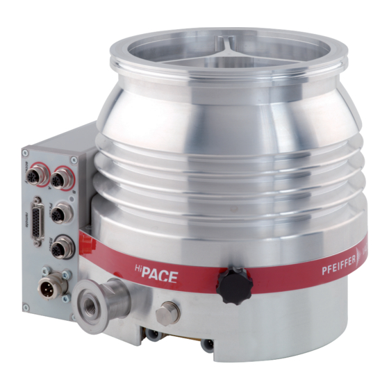
Product description 3 Product description 3.1 Function The turbopump forms a compact unit with the electronic drive unit. Pfeiffer Vacuum power supply packs provide the voltage supply. Fig. 2: HiPace 700 design 1 Electronic drive unit TC 400 Venting screw 2 Ground terminal... -
Page 18: Shipment
ID no. 000021320. 3.3.1 Product types The product designation of Pfeiffer Vacuum turbopumps from the HiPace series is composed of the family name, the size (which is based on the pumping speed of the vacuum pump) and, if required, an additional feature description. -
Page 19: Transportation And Storage
► Do not stack the products. ► Wear protective equipment, e.g. safety shoes. We recommend Pfeiffer Vacuum recommends keeping the transport packaging and original protective cov- Instructions for safe transport ► Transport the turbopump only within the permissible temperature limits. -
Page 20: Installation
Installation 5 Installation The installation of the turbopump and its fastening is of outstanding importance. The rotor of the turbo- pump revolves at very high speed. In practice it is not possible to exclude the risk of the rotor touching the stator (e.g. due to the penetration of foreign bodies into the high vacuum connection). The kinetic energy released acts on the housing and on the anchoring of the turbopump within fractions of a sec- ond. -
Page 21: Considering Earthquake Protection
● If the rotor blocks suddenly, make sure that all the torques generated are absorbed by the system on the operator side, and the high vacuum connection. ● Only use the approved mounting kits of Pfeiffer Vacuum for the high vacuum connec- tion of the turbopump. -
Page 22: Using A Splinter Shield Or Protective Screen
Safety connections, customer-side 5.2.3 Using a splinter shield or protective screen Pfeiffer Vacuum centering rings with splinter shield or protective screen in the high vacuum flange pro- tect the turbopump against foreign matter from the vacuum chamber. The pumping speed of the turbo- pump reduces according to the passage guide values and the size of the high vacuum flange. -
Page 23: Attaching Iso-K Flange Onto Iso-K
Flange connection ISO-K to ISO-F, bracket screws Connection with bracket screw 1. For the connection of the turbopump, use only the approved mounting kits from Pfeiffer Vacuum. 2. Connect the flange with the components of the mounting kit according to the figure. -
Page 24: Fig. 6: Flange Connection Iso-K To Iso-F, Hexagon Head Screw And Tapped Hole
Flange connection ISO-K to ISO-F, hexagon head screw and tapped hole Connection of the hexagon head screw and tapped hole 1. Only use the approved mounting kits of Pfeiffer Vacuum for the connection of the turbopump. 2. Place the collar flange over the high vacuum flange of the turbopump. -
Page 25: Attaching Iso-F Flange To Iso-F
Flange connection ISO-K to ISO-F, stud screw and through hole Connection of the stud screw and through hole 1. Only use the approved mounting kits of Pfeiffer Vacuum for the connection of the turbopump. 2. Place the collar flange over the high vacuum flange of the turbopump. -
Page 26: Attaching Cf Flange To Cf-F
Connection of the stud screw and tapped hole 1. Only use the approved mounting kits of Pfeiffer Vacuum for the connection of the turbopump. 2. Screw in the stud screws with the shorter end in the tapped holes on the counter flange. -
Page 27: Fig. 13: Flange Connection Cf-F, Stud Screw And Tapped Hole
Connection of the hexagon head screw and through holes 1. For the connection of the turbopump, use only the approved mounting kits from Pfeiffer Vacuum. 2. If used: Insert the protective screen or splinter shield with clamping lugs downwards in the turbo- pump high vacuum flange. -
Page 28: Connecting The Fore-Vacuum Side
Use the turbopump only in combination with a suitable backing pump that can deliver up to the required maximum fore-vacuum pressure. To achieve the fore-vacuum pressure, use a suitable vacuum pump or a pumping station from the Pfeiffer Vacuum range. In this case, the backing pump is also controlled directly via the turbopump electronic drive unit interfaces (e.g., relay box or connection cable). -
Page 29: Cooling Water Connection
Installation 5.4 Cooling water connection WARNING Risk of scalding from suddenly escaping hot cooling water The turbopump water connections are open to both sides. When connecting the cooling water supply, there is a risk of scalding from suddenly escaping, hot cooling water at over pressure. ►... -
Page 30: Connecting Accessories
● The use of other accessories for turbopumps is possible and requires settings in the configuration of the electronic drive unit. ● The desired accessory output is configured via RS-485 using Pfeiffer Vacuum display and control units or a PC. -
Page 31: Connecting The Electrical Supply
► Observe the installation instructions in the operating instructions for the relevant accessory. ► Note the existing configuration of existing connections. ► Use the Pfeiffer Vacuum display and control unit DCU 002, or a DCU with integrated power supply pack. -
Page 32: Establishing The Electric Connection
Connecting the electronic drive unit 1. Make sure that you have the correct supply voltage. 2. Make sure that the power supply pack main switch is off prior to connection. 3. Use a suitable connection cable from the Pfeiffer Vacuum accessories range. 32/60... - Page 33 Installation 4. Insert the connecting cable into the connection "DCin" on the electronic drive unit and close the bayonet lock. 5. Insert the connecting cable into the connection "DCout" on the power supply pack and close the bayonet lock. 33/60...
-
Page 34: Operation
Simultaneous loading by means of high drive power (gas throughput, fore-vacuum pressure), high heat radiation, or strong magnetic fields results in uncontrolled heating of the rotor and can destroy the vacuum pump. ► Consult Pfeiffer Vacuum before combining varying loads on the vacuum pump. Lower limit val- ues apply. NOTICE... -
Page 35: Operating Modes
Instructions for operation without control panel 1. Use only the approved Pfeiffer Vacuum mating plug with bridges on the connection of the elec- tronic drive unit. 2. Switch on the mains supply of the turbopump only immediately before operation. -
Page 36: Operation Via Field Bus
6.4.1 Operating mode display via LED LEDs on the electronic drive unit show the basic operating states of the vacuum pump. A differentiated error and warning display is only possible for operation with the Pfeiffer Vacuum display and control unit or a PC. -
Page 37: Temperature Monitoring
Operation Symbol LED status Display Meaning Currentless On, flashing "pumping station OFF", rotation speed ≤ 60 rpm Green On, inverse flashing "pumping station ON", set rotation speed not reached On, constant "pumping station ON", set rotation speed reached On, flashing "pumping station OFF", speed >... -
Page 38: Venting
General information for fast venting We recommend fast venting of larger volumes in 4 steps. 1. Use a Pfeiffer Vacuum venting valve for the turbopump, or match the valve cross-section to the size of the recipient and maximum venting rate. -
Page 39: Maintenance
5. Change the operating fluid reservoir at least every 4 years. 6. Have Pfeiffer Vacuum Service replace the rotor bearing of the turbopump at least every 4 years. 7. Consult with Pfeiffer Vacuum Service about shorter maintenance intervals for extreme loads or im- pure processes. -
Page 40: Fig. 19: Changing The Operating Fluid Reservoir
► Never use sharp, metallic tools (e.g., tweezers). ► Remove sealing rings by hand only, or with wooden or plastic sticks if necessary. You can find the safety data sheet can in the Pfeiffer Vacuum Download Center. Preparatory work 1. Do not apply any mechanical loads to the electronic drive unit. -
Page 41: Replacing The Electronic Drive Unit
Maintenance 5. Remove the operating fluid reservoir from the bearing housing using the tweezers. 6. Pull the old capillary rods out of the pump base with the tweezers. 7. Clean the screw cap with a clean, lint-free cloth. – Do not use cleaning agents. Installing the operating fluid reservoir 1. -
Page 42: Confirming The Rotation Speed Specification
4. Open and edit the parameter [P:777]. 5. Set the parameter [P:777] to the required value of the nominal rotation speed in Hertz. Alternative: A Pfeiffer Vacuum SpeedConfigurator for the one-time immediate setting of parameter [P:777] is included with the replacement units. -
Page 43: Decommissioning
2. Clean the turbopump externally with a lint-free cloth and a little isopropanol. 3. If necessary, arrange for Pfeiffer Vacuum Service to completely clean the turbopump. 4. Observe the total running time of the turbopump and if necessary, arrange for Pfeiffer Vac- uum Service to replace the bearing. -
Page 44: Disposing Of The Vacuum Pump
Decommissioning 8.3 Disposing of the vacuum pump WARNING Health hazard through poisoning from toxic contaminated components or devices Toxic process media result in contamination of devices or parts of them. During maintenance work, there is a risk to health from contact with these poisonous substances. Illegal disposal of toxic sub- stances causes environmental damage. -
Page 45: Malfunctions
► Follow the installation instructions for this turbopump. ► Observe the requirements regarding stability and design of the counter flange. ► Use only original accessories or fixing material approved by Pfeiffer Vacuum for the installation. WARNING Danger to life from poisoning where toxic process media leak from damaged connections Sudden twisting of the turbopump in the event of a fault causes fittings to accelerate. - Page 46 1. Reduce the process gas load. ● Rotor not running 1. Check the turbopump for noise development smoothly, defective bear- 2. Contact Pfeiffer Vacuum Service. ● Run-up time setpoint ad- 1. Extend the run-up time setpoint [P:700] via a dis- justed too low play and control unit.
- Page 47 Malfunctions Unusual noises during operation ● Rotor bearing damaged 1. Contact Pfeiffer Vacuum Service. ● Rotor damaged 1. Contact Pfeiffer Vacuum Service. ● Splinter shield or protec- 1. Check and correct the seat of the splinter shield or tive screen loose protective screen in the high vacuum flange.
-
Page 48: Service Solutions From Pfeiffer Vacuum
We are consistently striving to perfect our core competence, service for vacuum components. And our service is far from over once you’ve purchased a product from Pfeiffer Vacuum. It often enough really just begins then. In proven Pfeiffer Vacuum quality, of course. - Page 49 Service solutions from Pfeiffer Vacuum 5. Prepare the product for transport in accordance with the details in the declaration of contamination. a) Neutralize the product with nitrogen or dry air. b) Close all openings with airtight blank flanges. c) Seal the product in appropriate protective film.
-
Page 50: Spare Parts Hipace 700
Spare parts HiPace 700 11 Spare parts HiPace 700 Fig. 21: Spare parts HiPace 700 Posi- Designation Order number Note Pieces Quanti- tion Electronic drive unit refer to the rating plate depending on the TC 400 connection panel Operating fluid reser- PM 143 452 -T incl. -
Page 51: Accessories
Optionally available with splinter shield or protective screen. Power supply packs and display units Power supply packs for optimum voltage supply of Pfeiffer Vacuum products are characterized by their compact size and adapted power supply with maximum reliability. Display and operating units are used to check and adjust operating parameters. -
Page 52: Tbl. 16: Accessories
HPU 001, Handheld Programming Unit PM 051 510 -T PV TurboViewer Software to Visualize Units with RS-485 PM 061 740 PV TurboControl - Software for Pfeiffer Vacuum products with PV protocol PM 061 741 Extension cable M12 on M12 PM 061 747 -T... -
Page 53: Technical Data And Dimensions
Technical data and dimensions 13 Technical data and dimensions 13.1 General This section describes the basis for the technical data of Pfeiffer Vacuum turbopumps. Technical data Maximum values refer exclusively to the input as a single load. ● Specifications according to PNEUROP committee PN5 ●... - Page 54 Technical data and dimensions Classification advanced HiPace® 700 with HiPace® 700 with HiPace® 700 with TC 400 TC 400 TC 400 Ultimate pressure 1 · 10 5 · 10 1 · 10 Compression ratio for Ar > 1 · 10 >...
- Page 55 -20 – 55 °C -20 – 55 °C ture Weight 11.5 kg 17.4 kg 12.1 kg Tbl. 19: Technical data for HiPace 700 | 48 V Classification advanced HiPace® 700 with HiPace® 700 with HiPace® 700 with TC 400 TC 400 TC 400...
- Page 56 Technical data and dimensions Classification advanced HiPace® 700 with HiPace® 700 with HiPace® 700 with TC 400 TC 400 TC 400 Fore-vacuum max. for N 11 hPa 11 hPa 11 hPa Fore-vacuum max. for Ar 11 hPa 11 hPa 11 hPa Fore-vacuum max.
-
Page 57: Dimensions
Ø8 DN 160 ISO-K DN 25 ISO-KF / G 1/4” M8 (6x) 145.5 Fig. 22: HiPace 700 | TC 400 | DN 160 ISO-K Ø 8 DN 160 CF-F DN 25 ISO-KF / G 1/4“ M8 (6x) 145.5 Fig. 23:... -
Page 58: Fig. 24: Hipace 700 | Tc 400 | Dn 160 Iso-F
Technical data and dimensions Ø 8 DN 160 ISO-F DN 25 ISO-KF / G 1/4“ M8 (6x) 145.5 Fig. 24: HiPace 700 | TC 400 | DN 160 ISO-F 58/60... -
Page 59: Declaration Of Conformity
● Electromagnetic compatibility 2014/30/EU ● Restriction of the use of certain hazardous substances 2011/65/EU The authorized representative for the compilation of technical documents is Mr. Hel- mut Bernhardt, Pfeiffer Vacuum GmbH, Berliner Straße 43, 35614 Aßlar, Germany. Turbopump HiPace 700...
Need help?
Do you have a question about the HIPACE 700 and is the answer not in the manual?
Questions and answers
For cooling is there any specified direction for inlet and outlet.
For the Pfeiffer Vacuum HIPACE 700, the specified direction for the cooling water connections is as follows:
- Inlet (feed line) connects to the cooling water connection marked as "1"
- Outlet (return line) connects to the cooling water connection marked as "3"
This answer is automatically generated