Table of Contents
Advertisement
Quick Links
Advertisement
Table of Contents

Related Manuals for AXIOMTEK Qseven Q7B300


Summary of Contents for AXIOMTEK Qseven Q7B300
- Page 1 Q7B300 Qseven Module Development Board User’s Manual...
- Page 2 Axiomtek does not make any commitment to update the information in this manual. Axiomtek reserves the right to change or revise this document and/or product at any time without notice. No part of this document may be reproduced, stored in a retrieval system, or transmitted, in any form or by any means, electronic, mechanical, photocopying, recording, or otherwise, without the prior written permission of Axiomtek Co., Ltd.
-
Page 3: Esd Precautions
It discharges static electricity from your body. Wear a wrist-grounding strap, available from most electronic component stores, when handling boards and components. Trademarks Acknowledgments Axiomtek is a trademark of Axiomtek Co., Ltd. ® ® Intel and Celeron are trademarks of Intel Corporation. -
Page 4: Table Of Contents
Table of Contents Disclaimers ..................... ii ESD Precautions ................... iii Chapter 1 Introduction ..........1 Features ....................1 Specifications ..................2 Chapter 2 Board and Pin Assignments ....5 Board Dimensions and Fixing Holes ..........5 Board Layout ..................6 Installing Qseven Module and Thermal Solution ...... - Page 5 2.5.16 PCI-Express Mini Card Connector (CN25) ..........24 2.5.17 I2S Connector (CN26) ................25 2.5.18 Digital I/O Connector (CN31) ..............25 2.5.19 PCI-Express x1 Slots (CN32~CN34) ............26 2.5.20 Ethernet and USB 3.0 Ports (CN37 and CN41) ........27 2.5.21 Audio Jack (CN38) ..................
- Page 6 This page is intentionally left blank.
-
Page 7: Chapter 1 Introduction
Q7B300 Qseven Module Development Board Chapter 1 Introduction The Q7B300 is a new development baseboard for embedded Qseven Module and fully compliant with the Qseven Specification 2.0 standard. The Qseven is an open industry standard for Qseven modules, designed to be future proof and to provide a smooth transition path from legacy parallel interfaces to LVDS interfaces. -
Page 8: Specifications
Three USB 3.0 connectors (USB 2.0 compliant). Not supported. Supported. Digital I/O Four inputs and four outputs. Make sure you use the matching Q7B300 heatsink (P/N:7118Q311000E) or heatspreader (P/N : 7128Q311000E) for connecting to Axiomtek Qseven module. Introduction... - Page 9 Q7B300 Qseven Module Development Board Display One 40-pin connector for 18/24-bit single/dual channel LVDS and one 8-pin inverter connector. One eDP connector (switchable to LVDS with jumper setting). One DisplayPort. Expansion Interface Full-size PCI-Express Mini Card socket which comply with PCI-Express Mini Card Spec.
- Page 10 Q7B300 Qseven Module Development Board This page is intentionally left blank. Introduction...
-
Page 11: Board And Pin Assignments
Q7B300 Qseven Module Development Board Chapter 2 Board and Pin Assignments Board Dimensions and Fixing Holes Top View Front View Board and Pin Assignments... -
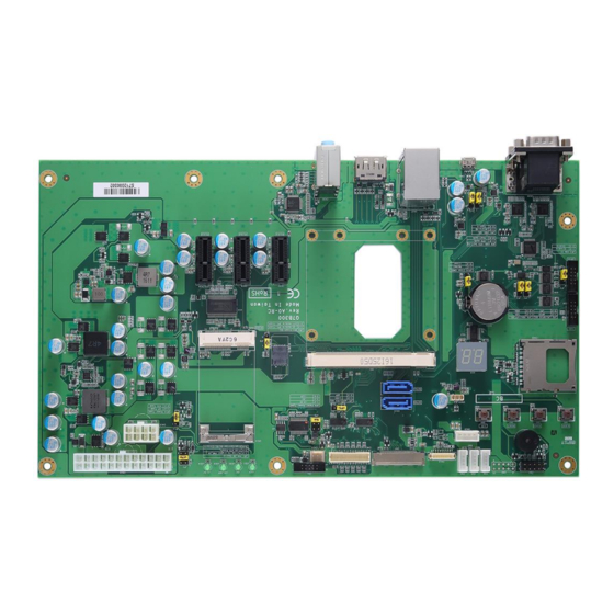
Page 12: Board Layout
Q7B300 Qseven Module Development Board Board Layout Top View Front View Board and Pin Assignments... -
Page 13: Installing Qseven Module And Thermal Solution
Q7B300 Qseven Module Development Board Installing Qseven Module and Thermal Solution For thermal dissipation, a heatsink enables the components on the Qseven module to dissipate heat efficiently. All heat generating components are thermally conducted to the heatsink in order to avoid hot spots. Below images illustrate how to install the heatsink. There is a protective plastic covering on the thermal pads. -
Page 14: Jumper Settings
Q7B300 Qseven Module Development Board Jumper Settings Jumper is a small component consisting of jumper clip and jumper pins. Install jumper clip on 2 jumper pins to close. And remove jumper clip from 2 jumper pins to open. Below illustration shows how to set up jumper. -
Page 15: Pwr_Ok Signal Source Selection (Jp1)
Q7B300 Qseven Module Development Board 2.4.1 PWR_OK Signal Source Selection (JP1) Use JP1 to select PWR_OK signal source. Function Setting Pull up to signal PWR_OK 1-2 close From ATX power (Default) 3-4 close From carrier DC/DC circuit 5-6 close 2.4.2 LPC/GPIO Selection (JP2) Use JP2 to select LPC or GPIO. -
Page 16: Usb Port 1 Otg/Host Mode Selection (Jp6)
Q7B300 Qseven Module Development Board 2.4.6 USB Port 1 OTG/Host Mode Selection (JP6) The USB port 1 supports two modes of operation: USB Host mode and OTG (On-The-Go) mode; they are selectable through jumper JP6. Function Setting Set USB port 1 to OTG mode 1-2 close Set USB port 1 to Host mode (Default) 2-3 close... -
Page 17: At/Atx Power Mode Setting (Jp11)
Q7B300 Qseven Module Development Board 2.4.11 AT/ATX Power Mode Setting (JP11) Use JP11 to select AT or ATX power mode. Function Setting AT mode 1-2 close ATX mode (Default) 2-3 close Board and Pin Assignments... -
Page 18: Connectors
Q7B300 Qseven Module Development Board Connectors Signals go to other parts of the system through connectors. Loose or improper connection might cause problems, please make sure all connectors are properly and firmly connected. Here is a summary table which shows all connectors on the hardware. Connector Description COM Wafer Connector... -
Page 19: Com Connectors (Cn1 And Cn39)
Q7B300 Qseven Module Development Board 2.5.1 COM Connectors (CN1 and CN39) The board has three serial port connectors. The CN1 is a 2x5-pin wafer connector for RS-232 interface from module. Signal Receive Data (RXD) Request To Send (RTS) Transmit Data (TXD) Clear To Send (CTS) Ground (GND) The CN39 is a double-deck DB-9 connector for RS-232/422/485 interface from carrier... -
Page 20: Front Panel Connector (Cn2)
Q7B300 Qseven Module Development Board 2.5.2 Front Panel Connector (CN2) The CN2 is a 2x5-pin connector for front panel interface. Signal Signal ATX_PSON# PWRLED- PWRLED+ PWRSW- PWRSW+ HW RST- HW RST+ HDDLED- HDDLED+ ATX Power Supply ON Short pin 1 and pin 2, ATX power supply is forcing to turn on state. Otherwise, system will control ATX power supply state. -
Page 21: I2C Connector (Cn5)
Q7B300 Qseven Module Development Board 2.5.4 I2C Connector (CN5) The CN5 is a 5-pin connector for I2C interface. Signal +3.3V I2C_CLK I2C_DATA 2.5.5 CAN Connector (CN6) The CN6 is a 5-pin connector for CAN interface. Controller Area Network (CAN or CAN-bus) is a message based protocol designed specifically for automotive applications but now is also used in other areas such as industrial automation and medical equipment. -
Page 22: Edp Connector (Cn7)
Q7B300 Qseven Module Development Board 2.5.6 eDP Connector (CN7) The eDP (embedded DisplayPort) interface is available through 40-pin connector (CN7). The eDP is a design to replace internal digital LVDS links in computer monitor panels and TV panels. You can select LVDS or eDP function with jumper JP7, see section 2.4.7. Also pin 1~4 VCCM can be set to +3.3V, +5V or +12V with jumper JP8, see section 2.4.8. -
Page 23: Lvds Connector (Cn9)
Q7B300 Qseven Module Development Board 2.5.7 LVDS Connector (CN9) This board has a 2x20-pin connector for LVDS LCD interface. It is strongly recommended to use the matching JST SHDR-40VS-B connector for LVDS interface. You can select LVDS or eDP function with jumper JP7, see section 2.4.7. Also pin 1~4 VCCM can be set to +3.3V, +5V or +12V with jumper JP8, see section 2.4.8. -
Page 24: Atx Power Connectors (Cn10 And Cn15)
Q7B300 Qseven Module Development Board 2.5.8 ATX Power Connectors (CN10 and CN15) Steady and sufficient power can be supplied to all components on the board by connecting power connector. Please make sure all components and devices are properly installed before connecting the power connector. External power supply plug fits into this connector in only one orientation. -
Page 25: Inverter Connector (Cn12)
Q7B300 Qseven Module Development Board 2.5.10 Inverter Connector (CN12) The CN12 is an 8-pin connector for LVDS inverter interface. We strongly recommend you to use the matching DF13-8S-1.25C connector to avoid malfunction. Signal VBL1 (+12V ) VBL1 (+12V ) VBL2 (+5V ) LVDS_BLEN LVDS_BLT_CTRL 2.5.11... -
Page 26: Usb 3.0 Wafer Connector (Cn20)
Q7B300 Qseven Module Development Board 2.5.13 USB 3.0 Wafer Connector (CN20) The CN20 is a 19-pin wafer connector for installing versatile USB peripherals such as keyboard, mouse, scanner, etc.; which is also compatible with USB 2.0 devices. Signal Signal USB_SSRX2- USB_SSRX2+ USB_SSTX2- USB_SSTX2+... -
Page 27: Qseven Connector (Cn23)
Q7B300 Qseven Module Development Board 2.5.15 Qseven Connector (CN23) The board comes with MXM 230-pin connector for Qseven interface. The MXM connector is a robust, low-cost edge connector that can handle high-speed signals. Signal Signal GBE_MDI3- GBE_MDI2- GBE_MDI3+ GBE_MDI2+ GBE_LINK100# GBE_LINK1000# GBE_MDI1- GBE_MDI0-... - Page 28 Q7B300 Qseven Module Development Board Signal Signal USB_VBUS USB_ID USB_P1- USB_P0- USB_P1+ USB_P0+ eDP0_TX0+/LVDS_A0+ (Q7B300 JP7) eDP1_TX0+/LVDS_B0+ eDP0_TX0-/LVDS_A0- (Q7B300 JP7) eDP1_TX0-/LVDS_B0- eDP0_TX1+/LVDS_A1+ (Q7B300 JP7) eDP1_TX1+/LVDS_B1+ eDP0_TX1-/LVDS_A1+ (Q7B300 JP7) eDP1_TX1-/LVDS_B1- eDP0_TX2+/LVDS_A2+ (Q7B300 JP7) eDP1_TX2+/LVDS_B2+ eDP0_TX2-/LVDS_A2- (Q7B300 JP7) eDP1_TX2-/LVDS_B2- LVDS_PPEN LVDS_BLEN eDP0_TX3+/LVDS_A3+ (Q7B300 JP7) eDP1_TX3+/LVDS_B3+ eDP0_TX3-/LVDS_A3- (Q7B300 JP7) eDP1_TX3-/LVDS_B3-...
- Page 29 Q7B300 Qseven Module Development Board Signal Signal PCIE0_TX- PCIE0_RX- LPC_AD0/GPIO0(Q7B300 JP2) LPC_AD1/GPIO1(Q7B300 JP2) LPC_AD2/GPIO2(Q7B300 JP2) LPC_AD3/GPIO3(Q7B300 JP2) LPC_CLK/GPIO4(Q7B300 JP2) LPC_FRAME#/GPIO5(Q7B300 JP2) SERIRQ/GPIO6(Q7B300 JP2) LPC_LDRQ#/GPIO7(Q7B300 JP2) VCC_RTC SPKR/GP_PWM_OUT2 FAN_TACHOIN/GP_TIMER_IN FAN_PWMOUT/GP_PWM_OUT1 SPI_MOSI SPI_CS0# SPI_MISO SPI_CS1# SPI_SCK MFG_NC4 VCC_5V_SB VCC_5V_SB MFG_NC0 MFG_NC2 MFG_NC1 MFG_NC3 Board and Pin Assignments...
-
Page 30: Pci-Express Mini Card Connector (Cn25)
Q7B300 Qseven Module Development Board 2.5.16 PCI-Express Mini Card Connector (CN25) The CN25 is a PCI-Express Mini Card connector supporting PCI-Express x1 link and USB 2.0 link. The PCI-Express Mini Card can be applied to either PCI-Express or USB 2.0. Signal Signal WAKE#... -
Page 31: I2S Connector (Cn26)
Q7B300 Qseven Module Development Board 2.5.17 I2S Connector (CN26) The CN26 is a 2x5-pin connector for I2S (Integrated Interchip Sound) interface. The I2S is an electrical serial bus interface standard used for connecting digital audio devices. You can select I2S or HDA support with jumper JP4, see section 2.4.4. Signal I2S_WS +3.3V... -
Page 32: Pci-Express X1 Slots (Cn32~Cn34)
Q7B300 Qseven Module Development Board 2.5.19 PCI-Express x1 Slots (CN32~CN34) The Q7B300 supports up to four PCI-Express x1: PCIe 0~3. The PCIe 0 is routed to CN25, and the PCIe 1~3 are routed to CN32~CN34. Signal Signal +12V PRSNT1# +12V +12V +12V +12V... -
Page 33: Ethernet And Usb 3.0 Ports (Cn37 And Cn41)
Q7B300 Qseven Module Development Board 2.5.20 Ethernet and USB 3.0 Ports (CN37 and CN41) The board is equipped with high performance plug and play Ethernet interface fully compliant with the IEEE 802.3 standard. The Ethernet port uses RJ-45 connector. Connection can be established by plugging one end of the Ethernet cable into this RJ-45 connector and the other end to a 1000/100/10-Base-T hub. -
Page 34: Audio Jack (Cn38)
Q7B300 Qseven Module Development Board 2.5.21 Audio Jack (CN38) The Q7B300 comes equipped with codec AL662. Install audio driver, then attach audio devices to CN38. Pin Color Signal Blue LINE IN Green LINE OUT Pink Use jumper JP4 to select I2S or HDA function, see section 2.4.4. Note 2.5.22 DisplayPort Connector (CN40) -
Page 35: Push Buttons
Q7B300 Qseven Module Development Board Push Buttons The board has four push buttons, see table below. Push Button Description Sleep button Power button Reset button LID button LED Indicators The board has four LEDs and one dual 7-segment LED display. See table below for detailed information.
Need help?
Do you have a question about the Qseven Q7B300 and is the answer not in the manual?
Questions and answers