
Related Manuals for Clarke CGP75F


Summary of Contents for Clarke CGP75F
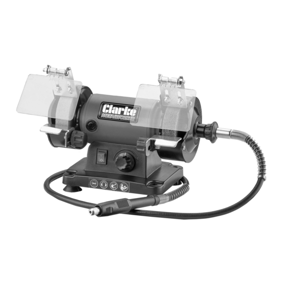
- Page 1 MINI GRINDER-POLISHER WITH FLEX EXTENSION MODEL NO: CGP75F PART NO: 6500072 OPERATION & MAINTENANCE INSTRUCTIONS ORIGINAL INSTRUCTIONS LS1119 - ISS 1...
-
Page 2: Environmental Recycling Policy
INTRODUCTION Thank you for purchasing this CLARKE mini grinder-polisher with flex extension. Before attempting to use this product, please read this manual thoroughly and follow the instructions carefully. In doing so you will ensure the safety of yourself and that of others around you, and you can look forward to your purchase giving you long and satisfactory service. -
Page 3: Specifications
SPECIFICATIONS Model Number CGP75F Part Number 6500072 Dimensions (D x W x H) 127 x 243 x 180 mm Weight 2.71 kg Rated Voltage 230 V~ 50 Hz Rated Input Wattage 120 W Variable Speed 0 - 9900 rpm Wheel dimensions... -
Page 4: Power Tool Safety Warnings
POWER TOOL SAFETY WARNINGS 1) WORK AREA 1. Keep the work area clean and well lit. Cluttered and dark areas invite accidents. 2. Do not operate power tools in explosive atmospheres, such as in the presence of flammable liquids, gases or dust. Power tools create sparks which may ignite the dust or fumes. - Page 5 4) POWER TOOL USE AND CARE 1. Do not force the power tool. Use the correct accessories for your application. The correct power tool will do the job better and safer at the rate which it was designed. 2. Do not use the power tool if the switch does not turn it on and off. Any power tool that cannot be controlled with the switch is dangerous and must be repaired.
-
Page 6: Bench Grinder Safety Warnings
Check for misalignment or binding of moving parts, breakage of parts and any other condition that may affect the tool's operation. A part that is damaged should be properly repaired or replaced at you local CLARKE service department. Following this rule will reduce the risk of electric shock, fire or serious injury. -
Page 7: Electrical Connections
ELECTRICAL CONNECTIONS WARNING: READ THESE ELECTRICAL SAFETY INSTRUCTIONS THOROUGHLY BEFORE CONNECTING THE PRODUCT TO THE MAINS SUPPLY. Connect the mains lead to a standard, 230 Volt (50Hz) electrical supply through an approved BS 1363 plug or a suitably fused isolator switch. If the plug has to be changed because it is not suitable for your socket, or because of damage, it must be removed and a replacement fitted, following the wiring instructions shown below. -
Page 8: Carton Contents
CARTON CONTENTS The following items should be supplied in the carton. If any parts are missing or damaged, please contact the CLARKE dealer where you purchased the Grinder/Polisher. 1 x Grinder/Polisher 2 x Spark Deflector / Eye Shield 1 x Flexible Shaft Attachment... -
Page 9: Before Use
BEFORE USE INSTALLING THE TOOL RESTS 1. Fix the tool rests in place with the thumb screw as shown. • The tool rests are adjustable and should be positioned less then 2 mm from the grinding wheels. • Ensure that the tool rest is firmly fixed and horizontal. -
Page 10: Operation
The grinding wheel may need dressing occasionally. Only dress the wheel with a proper dressing tool whilst wearing safety goggles or glasses. If in doubt seek professional advice. Dressing tools are available from your CLARKE dealer. Grinding wheel dresser model no ET125;- part no 1700225... - Page 11 USING THE FLEXIBLE SHAFT ATTACHMENT CONNECT THE FLEXIBLE SHAFT 1. Insert the flexible shaft into the right side of the grinder as shown and tighten the locking collar as shown. NOTE: The locking collar has a left hand thread FITTING THE BITS 1.
-
Page 12: Replacing The Grinding Wheels
• After mounting, the wheel should be test run for approximately 1 minute without load. If you notice excessive vibration, have your machine checked by the CLARKE service department. Parts & Service: 020 8988 7400 / E-mail: Parts@clarkeinternational.com or Service@clarkeinternational.com... -
Page 13: Parts Diagram
PARTS DIAGRAM Parts & Service: 020 8988 7400 / E-mail: Parts@clarkeinternational.com or Service@clarkeinternational.com... -
Page 14: Part List
PART LIST NOTE: Not all parts are available as a spare item. M10 Nut (left hand thread) Toothed Washer Flange Right Tool Rest Buffing wheel Speed Dial controller Grinding wheel On/Off Switch M10 Nut (right hand thread) Baseplate Shaft Coupler Foot Flexible Shaft attachment Brush... -
Page 15: Declaration Of Conformity
DECLARATION OF CONFORMITY Parts & Service: 020 8988 7400 / E-mail: Parts@clarkeinternational.com or Service@clarkeinternational.com...
Need help?
Do you have a question about the CGP75F and is the answer not in the manual?
Questions and answers