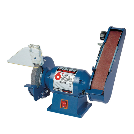
Summary of Contents for Clarke METALWORKER CBG6SB
- Page 1 BENCH GRINDER WITH SANDING BELT MODEL NO: CBG6SB PART NO: 6500032 OPERATING & MAINTENANCE INSTRUCTIONS ORIGINAL INSTRUCTIONS GC0820-rev 3...
-
Page 2: Environmental Protection
INTRODUCTION Thank you for purchasing this CLARKE Bench Grinder with sanding belt. Before attempting to use this product, please read this manual thoroughly and follow the instructions carefully. In doing so you will ensure the safety of yourself and that of others around you, and you can look forward to your purchase giving you long and satisfactory service. -
Page 3: General Safety Rules
GENERAL SAFETY RULES CAUTION: FAILURE TO FOLLOW THESE PRECAUTIONS COULD RESULT IN PERSONAL INJURY, AND/OR DAMAGE TO PROPERTY. PLEASE KEEP THESE INSTRUCTIONS IN A SAFE PLACE FOR FUTURE REFERENCE. WORK ENVIRONMENT 1. Keep the work area clean, tidy and well lit. Cluttered and dark areas invite accidents 2. -
Page 4: Electrical Safety
6. NEVER attempt any repairs yourself. If you have a problem with this product contact your local CLARKE dealer. 7. Do not use the tool for any purpose than that described in this manual. -
Page 5: Grinding Stone Safety
4. When operating a power tool outdoors, use an extension cable suitable for outdoor use. Use of a cable suitable for outdoor use reduces the risk of electric shock. BELT/DISC SANDER SAFETY 1. ALWAYS wear a dust mask when using this machine. Be aware that harmful or toxic dusts could be produced when sanding some woods. -
Page 6: Bench Grinder Safety Warnings
9. Abrasive products shall be handled and transported with care. Abrasive products shall be stored in such a manner that they are not subjected to mechanical damage and harmful environmental influences. 10. Do not use separate reducing bushes or adapters to adapt large hole abrasive wheels. -
Page 7: Electrical Connections
ELECTRICAL CONNECTIONS WARNING! READ THESE ELECTRICAL SAFETY INSTRUCTIONS THOROUGHLY BEFORE CONNECTING THE PRODUCT TO THE MAINS SUPPLY. Before switching the product on, make sure that the voltage of your electricity supply is the same as that indicated on the rating plate. This product is designed to operate on 230VAC 50Hz. - Page 8 Top Roller Securing Knob The items above should be supplied with the grinder. If any items are missing or damaged, please contact the Clarke dealer where you purchased the product. Position the machine in good light, and fixed to a suitable workbench using the boltholes in the machine base.
-
Page 9: Using The Machine
3. Ensure that the bench grinder is mounted securely to a suitable, stable work surface using the four bolt holes provided in the base. We recommend that your Clarke Bench Grinder is secured to your workbench before operation. Do not overtighten the mounting bolts as this could damage the plastic base. - Page 10 2. Allow the machine to reach full speed, then hold the tool firmly on the tool rest and apply slight pressure on to the grinding wheel, allowing the grinder to do the work. NOTE: Never attempt to grind a piece of metal that is thinner than the gap between the tool rest and the grinding wheel (1.6 mm).
-
Page 11: Using Your Grinder
USING YOUR GRINDER WARNING: FRAGMENTS FROM A BROKEN/DETACHED GRINDING WHEEL CAN CAUSE INJURY. WARNING: ENSURE THAT THE WORKING POSITION ADOPTED DOES NOT CAUSE OPERATOR FATIGUE WHICH MAY LEAD TO LOSS OF CONTROL OF THE TOOL BEING GROUND. WARNING: THE GRINDING WHEEL WILL CONTINUE TO ROTATE BRIEFLY AFTER THE OFF SWITCH HAS BEEN PRESSED. -
Page 12: General Maintenance
Do not attempt to repair the bench grinder unless you are qualified to do so. The drive motor and bearings are sealed units and require no regular maintenance. Should you require assistance, contact your local Clarke service agent. Parts & Service: 020 8988 7400 / E-mail: Parts@clarkeinternational.com or Service@clarkeinternational.com... - Page 13 The grinding stone will wear down with use and may well go out of true. Use a dressing wheel or stone grader to correct the trueness and to remove worn, glazed grains from the stone. The stone will have a finite life expectancy, dependant upon the nature of the work being done.
-
Page 14: Dressing A New Stone
New grinding stones are frequently not true or in time can become grooved, glazed (built-up), out of round or otherwise mis-shapen. To correct these defects, a grinding stone dresser is available from your Clarke dealer. • ET125 Grinding Wheel Dresser - Part No:1700225 •... -
Page 15: Cleaning And Storage
5. Slide the belt off and replace with a new one, ensuring it lies centrally on the top and bottom rollers 6. Retighten the top roller securing knob till it becomes firm but NOT too tight. 7. Tighten the belt tension adjuster nut until it also becomes firm. DO NOT overtighten. -
Page 16: Component Parts Diagram
COMPONENT PARTS DIAGRAM Parts & Service: 020 8988 7400 / E-mail: Parts@clarkeinternational.com or Service@clarkeinternational.com... -
Page 17: Component Parts List
COMPONENT PARTS LIST Description Part No Description Part No Bolt HT6SB001 Bolt HT6SB031 Outer Guard HT6SB002 Washer HT6SB032 HT6SB003 Spring Washer HT6SB033 Flange HT6SB004 Screw HT6SB034 Paper Blotter HT6SB005 Switch HT6SB035 Wheel HT6SB006 Base HT6SB036 Ring Guard HT6SB007 Base Plate HT6SB037 Screw HT6SB008... -
Page 18: Specifications
COMPONENT PARTS LIST Description Part No Description Part No Top Roller HT6SB061 HT6SB072 Belt (5-pack) HT6SB062 Spring HT6SB073 Outer cover HT6SB063 Spring Pin HT6SB074 Screw HT6SB064 HT6SB075 Spring Washer HT6SB065 Knob HT6SB076 Washer HT6SB066 Spring Washer HT6SB077 Square Neck Screw HT6SB067 Washer HT6SB078... -
Page 19: Declaration Of Conformity
DECLARATION OF CONFORMITY Parts & Service: 020 8988 7400 / E-mail: Parts@clarkeinternational.com or Service@clarkeinternational.com...


Need help?
Do you have a question about the METALWORKER CBG6SB and is the answer not in the manual?
Questions and answers