Clarke CBG8W Operating & Maintenance Manual
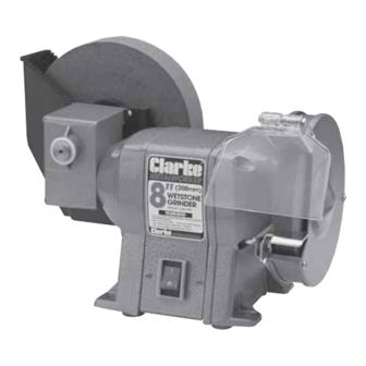
8” wetstone bench grinder
Hide thumbs
Also See for CBG8W:
- Operating & maintenance instructions (17 pages) ,
- Operating & maintenance instructions (17 pages)

Related Manuals for Clarke CBG8W


Summary of Contents for Clarke CBG8W
- Page 1 8” WETSTONE 8” WETSTONE BENCH GRINDER BENCH GRINDER OPERATING & MAINTENANCE INSTRUCTIONS 0805...
- Page 2 Thank you for purchasing this Clarke Bench Grinder. Before attempting to operate this bench grinder please read this instruction manual thoroughly and follow all directions carefully. This is for your own safety and that of others around you, and to help you achieve long and trouble free service from your bench grinder.
- Page 3 ELECTRICAL CONNECTIONS WARNING! THIS MACHINE MUST BE EARTHED This product is provided with a standard 13 amp, 230 volt (50Hz). BS 1363 plug, for connection to a standard, domestic electrical supply. Should the plug need changing at any time, ensure that a plug of identical specification is used. IMPORTANT: The wires in the mains lead should be wired up in accordance with the following colour code: Green &...
- Page 4 ASSEMBLY AND INSTALLATION Fix the grinder to the bench using suitable screws or bolts through the holes In the grinder base. Do not overtighten the securing screws. The grinder has rubber mounting feet to help minimise vibration, and these will not be effective if compressed too tightly. If using bolts, make sure they will not work loose under vibration by fitting locknuts or similar.
- Page 5 MAINTENANCE AND REPLACING WHEELS WARNING Disconnect the grinder from the mains supply before fitting replacement wheels, cleaning or adjustment. Keep the machine clean by wiping off dust with a clean cloth, and occasionally blowing the grinder through with air. Always wear protective goggles when blowing through with compressed air.
- Page 6 PARTS DIAGRAM...
- Page 7 PARTS LIST Item Description Part No. Screw HT8481901 Washer HT8481902 Cover HT8481903 Water Trough HT8481904 Rubber Cork HT8481905 HT8481906 Worm Wheel HT8481907 Worm HT8481908 Both HT8481909 Short Axis HT8481910 Journal Bearing HT8481911 Worm Gear Case HT8481912 Big Washer HT8481913 Wheel Flange HT8481914 Wet Wheel HT8481915...
Need help?
Do you have a question about the CBG8W and is the answer not in the manual?
Questions and answers