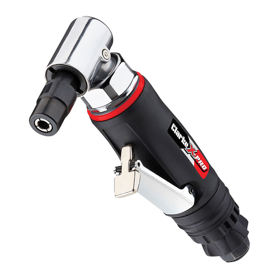
Summary of Contents for Clarke X-Pro CAT206
- Page 1 ¼”RIGHT ANGLE DIE GRINDER MODEL NO: CAT206 PART NO: 3120523 OPERATING & MAINTENANCE INSTRUCTIONS ORIGINAL INSTRUCTIONS GC1019 - ISS 1...
-
Page 2: Specifications
INTRODUCTION Thank you for purchasing this CLARKE Die Grinder which is ideal for light tasks such as automotive porting & polishing applications. Before attempting to use this product, please read this manual thoroughly and follow the instructions carefully. In doing so you will ensure the safety of yourself and that of others around you, and you can look forward to your purchase giving you long and satisfactory service. -
Page 3: General Safety Rules
GENERAL SAFETY RULES CAUTION: FAILURE TO FOLLOW THESE PRECAUTIONS COULD RESULT IN PERSONAL INJURY, AND/OR DAMAGE TO PROPERTY. THE WORK ENVIRONMENT 1. ALWAYS keep the work area clean and tidy. 2. ALWAYS dress appropriately - Do not wear loose clothing or jewellery. Tie long hair out of the way. - Page 4 • The tool is not in use. • The tool will be left unattended. • Moving to another work area. 14. NEVER use the tool if it is defective or operating abnormally. 15. Avoid damaging the tool for example by applying excessive force. 16.
-
Page 5: Compressed Air Requirements
COMPRESSED AIR REQUIREMENTS WARNING: COMPRESSED AIR CAN BE DANGEROUS. ENSURE THAT YOU ARE FAMILIAR WITH ALL PRECAUTIONS RELATING TO THE USE OF COMPRESSORS AND COMPRESSED AIR SUPPLY. A typical air line layout is shown below. If an automatic in-line filter/regulator is used it will keep the tool in good condition, but should be regularly checked and topped up with oil. - Page 6 OVERVIEW When opening the carton for the first time, check that all the items are present. Any damage or deficiency should be reported to your CLARKE dealer immediately. NO DESCRIPTION...
-
Page 7: Before Use
1. Remove the plastic blanking plug from the air inlet connection. 2. Pour 2-3 drops of CLARKE airline oil into the inlet port. This should be done regardless of whether or not a lubricated air supply is to be used. -
Page 8: Adjusting The Speed
INSTALLING THE COLLET 1. Select the grinding stone you require. 2. Two collets of different sizes are provided. Select whichever fits the shank of the stone you have chosen. • The larger collet may already be installed in the grinder. 3. -
Page 9: Operating The Die Grinder
If the tool is to be stored, or is idle for longer than 24 hours, run a few drops of CLARKE air line oil into the air inlet, and run the tool for 5 seconds in order to lubricate the internal parts. -
Page 10: Troubleshooting
2. Motor parts worn. 2. Return to CLARKE dealer for repair. 3. Worn or sticking 3. Drip air tool lubricating mechanism due to oil into air inlet. Allow oil lack of lubricant. -
Page 11: Maintenance
2. After extensive use, remove the inlet screen filter and flush out the mechanism with gum solvent oil or an equal mixture of CLARKE air- line oil and paraffin. Allow to dry before use. SERVICE AND REPAIR 1. If the tool runs erratically or becomes inefficient although the air supply is in good order, it may be necessary to dismantle the air motor and replace any worn or damaged parts. - Page 12 3. You may prefer to take the tool to your CLARKE dealer if internal maintenance is required. GREASING The right angle drive is fitted with a grease nipple to provide a facility for lubrication of the drive gears. 1. After extensive use, apply a shot of general purpose grease using a suitable grease gun.
-
Page 13: Declaration Of Conformity
DECLARATION OF CONFORMITY Parts & Service: 020 8988 7400 / E-mail: Parts@clarkeinternational.com or Service@clarkeinternational.com... -
Page 14: Parts List
PARTS LIST Description No Description Main Housing Set pin Housing liner Rotor Bushing Rotor blade O-ring Cylinder Trigger Bushing Lever Front plate Spring Steel ball Bearing Trigger pin Gear Air inlet Seal ring Spring Lock ring Hex nut O-ring Right angle gear head Air regulator Grease cap O-ring... -
Page 15: Component Parts Diagram
COMPONENT PARTS DIAGRAM GUARANTEE This product is guaranteed against faulty manufacture for a period of 12 months from the date of purchase. Please keep your receipt which will be required as proof of purchase. This guarantee is invalid if the product is found to have been abused or tampered with in any way, or not used for the purpose for which it was intended.


Need help?
Do you have a question about the X-Pro CAT206 and is the answer not in the manual?
Questions and answers