Table of Contents
Advertisement
Quick Links
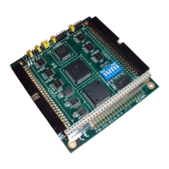
PCM-3724
PC/104 48-bit Digital I/O Module
Packing List
Before installation, please make sure that you have:
• PCM-3724 Module
• Startup Manual
If anything is missing or damaged, contact your
distributor or sales representative immediately.
User Manual
For more detailed information on this product,
please refer to the PCM-3724 User Manual on the
CD-ROM (PDF format).
Documents\Hardware Manuals\PCM\PCM-3724
Declaration of Conformity
FCC Class A
This equipment has been tested and found to comply with
the limits for a Class A digital device, pursuant to part 15 of
the FCC Rules. These limits are designed to provide reason-
able protection against harmful interference when the
equipment is operated in a commercial environment. This
equipment generates, uses, and can radiate radio frequency
energy and, if not installed and used in accordance with the
instruction manual, may cause harmful interference to radio
communications. Operation of this equipment in a residen-
tial area is likely to cause interference in which case the
user is required to correct interference at his own expense.
CE
This product has passed the CE test for environmental spec-
ifications when shielded cables are used for external wiring.
We recommend the use of shielded cables. This kind of
cable is available from Advantech. Please contact your local
supplier for ordering information.
Overview
The PCM-3724 is a PC/104-standard DI/O module which
attaches to the piggyback connector on your CPU card or
PC/104 CPU module. The PCM-3724's two Intel 8255 PPI
compatible chips provide 48 bits of parallel digital input/
output. Buffered inputs and outputs offer high driving
capacity.The module's 48 bits are divided into six 8-bit I/O
ports: A0, B0, C0, A1, B1 and C1. You can configure each
port as either an input or output in software.
Notes
For more information on this and other Advantech
products, please visit our websites at:
http://www.advantech.com/eAutomation
For technical support and service:
http://www.advantech.com/support/
This startup manual is for PCM-3724.
Part No. 2003724111
1
Startup Manual
• Driver CD
2nd Edition
June 2011
Switch and Jumper Settings
Base Address Selection (SW1)
Switch SW1 sets the module's base (beginning)
address. Valid base addresses range from Hex 000 to
Hex 3F0. We set the PCM-3724 for a base address
of Hex 300 at the factory. If you need to adjust it to
some other address range, set switch SW1 as shown
below:
Advertisement
Table of Contents

Related Manuals for Advantech PCM-3724


Summary of Contents for Advantech PCM-3724
- Page 1 Hex 3F0. We set the PCM-3724 for a base address communications. Operation of this equipment in a residen- of Hex 300 at the factory. If you need to adjust it to...
- Page 2 Hardware Installation After the device driver installation is completed, you Interrupt Mode (JP5, JP6) can now go on to install the PCM-3724 module on your Jumpers JP5 controls interrupt line PC00, and jumper computer. JP6 controls interrupt line PC10. The DIS setting for...
- Page 3 PIN Assignments J4 - Port 2 J3 - Port 1 Startup Manual...
Need help?
Do you have a question about the PCM-3724 and is the answer not in the manual?
Questions and answers