Table of Contents
Advertisement
Quick Links
Advertisement
Table of Contents

Related Manuals for Advantech PCL-722


Summary of Contents for Advantech PCL-722
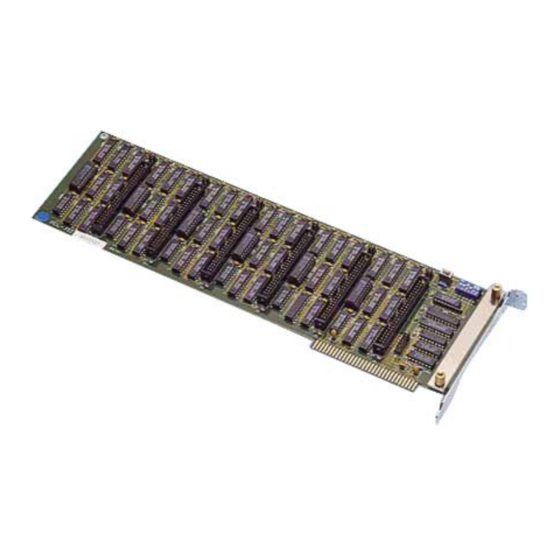
- Page 1 PCL-722 144-ch Digital I/O ISA Card User Manual...
- Page 2 No part of this man- ual may be reproduced, copied, translated or transmitted in any form or by any means without the prior written permission of Advantech Co., Ltd. Information provided in this manual is intended to be accurate and reli- able.
- Page 3 Product Warranty (2 years) Advantech warrants to you, the original purchaser, that each of its prod- ucts will be free from defects in materials and workmanship for two years from the date of purchase. This warranty does not apply to any products which have been repaired or...
- Page 4 This product has passed the CE test for environmental specifications when shielded cables are used for external wiring. We recommend the use of shielded cables. This kind of cable is available from Advantech. Please contact your local supplier for ordering information.
- Page 5 Safety Instructions Read these safety instructions carefully. Keep this User's Manual for later reference. Disconnect this equipment from any AC outlet before cleaning. Use a damp cloth. Do not use liquid detergents for cleaning. For plug-in equipment, the power outlet socket must be located near the equipment and must be easily accessible.
- Page 6 The sound pressure level at the operator's position according to IEC 704- 1:1982 is no more than 70 dB (A). DISCLAIMER: This set of instructions is given according to IEC 704-1. Advantech disclaims all responsibility for the accuracy of any statements contained herein. Safety Precaution - Static Electricity Follow these simple precautions to protect yourself from harm and the products from damage.
-
Page 7: Table Of Contents
Software Overview............5 Chapter 2 Installation ............8 Unpacking ................. 8 Driver Installation ............. 9 Figure 2.1: Advantech Automation Software Setup ..9 Figure 2.2:Different Options for Driver Setup .... 10 Hardware Installation ............11 Chapter 3 Signal Connections ........14 Overview ................. - Page 8 PCL-722 User Manual viii...
- Page 9 Introduction This chapter contains information on the PCL-722 and instruction on card config- uration in order to match your applica- tion and prepare it for installation on your system. Sections include: • Features • Specifications • Applications • Installation Guide...
-
Page 10: Chapter 1 Introduction
These inputs are buffered and can be con- nected to IRQ 2, 3, 4, 5, 6 and 7. The PCL-722 is a full-size PC add-on card and can fit any full-length expansion slot in the IBM PC XT/AT or compatible computer running at any clock rate. -
Page 11: Digital Output
1.2.2 Digital Output Channels: 144 (24 channels x 6 ports) shared with input Compatibility: 5V/TTL Output Voltage: Port A, B, C Logic 0: 0.4 V max. @ 24 mA Logic 1: 2.4 V min. @ -15 mA 1.2.3 General Specifications Power Consumption: Typical: +5 V @ 1.3 A Max.: +5 V @ 1.8 A Operating Temperature: 0 ~ 60°C (32 ~ 140°F) -
Page 12: Installation Guide
1.4 Installation Guide Before you install your PCL-722 card, please make sure you have the fol- lowing necessary components: • PCL-722 DA&C card • PCL-722 User Manual • Driver software Advantech DLL drivers (in the companion CD-ROM) • PC or workstation with a ISA-bus slot... -
Page 13: Software Overview
1.5 Software Overview Advantech offers a rich set of DLL drivers, third-party driver support and application software to help fully exploit the functions of your PCL-722 card: • Device Drivers (on the companion CD-ROM) • LabVIEW driver • Advantech ActiveDAQ Pro Programming Choices for DA&C Cards... - Page 14 PCL-722 User Manual...
- Page 15 Installation This chapter contains a package item checklist, proper instructions for unpacking and step-by-step procedures for card installation. Sections include: • Unpacking • Driver Installation • Hardware Installation • Device Configuration...
-
Page 16: Chapter 2 Installation
Chapter 2 Installation 2.1 Unpacking After receiving your PCL-722 package, please inspect its contents first. The package should contain the following items: • PCL-722 card • Companion CD-ROM (Device Drivers included) • User Manual The PCL-722 cards harbor certain electronic components vulnerable to electrostatic discharge (ESD). -
Page 17: Driver Installation
2.2 Driver Installation We recommend you install the driver before you plug the PCL-722 into your system, since this will guarantee a smooth installation process. The Advantech Device Drivers Setup program for the PCL-722 card is included in the companion CD-ROM that is shipped with your DA&C card package. -
Page 18: Figure 2.2:Different Options For Driver Setup
Figure 2.2: Different Options for Driver Setup For further information on driver-related issues, an online version of the Device Drivers Manual is available by accessing the following path: Start/Advantech Automation/Device Manager/Device Driver’s Manual PCL-722 User Manual... -
Page 19: Hardware Installation
4. Touch the metal part on the surface of your computer to neutralize the static electricity that might be on your body. 5. Insert the PCL-722 card into a ISA slot. Hold the card only by its edges and carefully align it with the slot. Insert the card firmly into place. - Page 20 PCL-722 User Manual...
- Page 21 Signal Connections This chapter provides useful informa- tion about how to connect input and output signals to the PCL-722 via the I/O connector. Sections include: • Overview • Switch & Jumper Settings • Signal Connections...
-
Page 22: Chapter 3 Signal Connections
A good signal connection can avoid unnecessary and costly dam- age to your PC and other hardware devices. This chapter provides useful information on how to connect input and output signals to the PCL-722 via the I/O connector. 3.2 Switch & Jumper Settings The PCL-722 card has two function jumper settings. -
Page 23: Base Address Selection
I/O space. Some I/O address locations will be occupied by internal I/O and your peripherals. In order to avoid conflict with these devices, the PCL-722 address can be set by a 6 position DIP switch and placed anywhere in the IBM PC decoded external UO space. -
Page 24: 96/144-Bit Mode Setting
3.2.2 96/144-bit Mode Setting The PCL-722 can limit the 32 required addresses to 16, there- fore, the digital I/O is limited to 96 bits. SW2 (see Fig. 3.2 below) sets the number of usable I/O. The PCL-722 card should be left in the 144 bit mode unless this address con- flicts with the addresses of other peripherals already installed or those to be installed in neighbouring slots. -
Page 25: Interrupt Settings
You can set the address according to the information given in Table 3.1. 3.2.3 Interrupt Settings Pins PC-0 and PC-3 of each channel of the PCL-722 generate hardware interrupts and can be set to any of the interrupt request lines IRQ2, 3, 4, 5, 6 and 7. -
Page 26: Signal Connections
3.3 Signal Connections The PCL-722 card emulates MODE 0 of 8255 PPI, and is pin compatible with popular industrial solid state I/O racks and modules such as those manufactured by OPTO-22, Potter Brumfield, Gordos, and others. The PCL-722 has six 50-pin male IDC connectors that inter- face with position OPTO-22 racks 8, 16 and 24. -
Page 27: Table 3.3:Cfg Register Format (Mode 0)
Table 3.2: 8255 Address Map Register Address Function Port A BASE ADDRESS +0 Read/Write Port B BASE ADDRESS +1 Read/Write Port C BASE ADDRESS +2 Read/Write CFG REG BASE ADDRESS +3 Write Only Example” Base address set at 300 Table 3.3: CFG register format (mode 0) Port A Port B Port C... -
Page 28: Table 3.4:8255 Mode 0 Configuration Table
PC 2 PC 1 PC 0 PB 7 PB 6 PB 5 PB 4 PB 3 PB 2 PB 1 PB 0 PA 7 PA 6 PA 5 PA 4 PA 3 PA 2 PA 1 PA 0 PCL-722 User Manual... -
Page 29: Interrupt Handling
3.4 Interrupt Handling The PCL-722 has two lines (PC-0, PC-3) for each channel to generate hardware interrupt. The interrupts are edge-triggered. PC-0 traps a rising edge signal, while PC-3 traps a falling edge signal. To use the interrupts, simply insert the appropriate IRQ jumper to select the desired interrupt level (IRQ 2-7). - Page 30 For example, lxx0 (1000, 1010, 1100, 1110) Although interrupt signals are normally received from external peripherals, the PCL-722 can also execute a (test) output signal to simulate an interrupt being inputted from an external device. See the example in Appendix.
- Page 31 Programming Examples...
-
Page 32: Appendix A Programming Examples
Appendix A Programming Examples The PCL-722 is easily programmed and the following section lists some program examples. All the program examples below have been fully tested on PC-XT/AT or compatible computers. Note: The following programs should be run under Turbo C version 1.5 or 2.0. - Page 33 Appendix A...
- Page 34 PCL-722 User Manual...
- Page 35 Appendix A...
- Page 36 PCL-722 User Manual...
- Page 37 Block Diagram...
-
Page 38: Appendix B Block Diagram
Appendix B Block Diagram PCL-722 User Manual... - Page 39 PC I/O PORT ADDRESS MAP...
-
Page 40: Appendix C Pc I/O Port Address Map
Appendix C PC I/O Port Address Map I/O Address Range (Hex) Function 000-1FF Base system Reserved Came control 202-277 Reserved 278-27F Second printer port 280-2F7 Reserved 2F8-2FF COM2 300-377 Reserved 3713-37F First printer port 380-3AF Reserved 3B0-3BF Mono Disp/Print adapter 3C0-3CF Reserved 3D0-3DF...
Need help?
Do you have a question about the PCL-722 and is the answer not in the manual?
Questions and answers