Table of Contents
Advertisement
Quick Links
Advertisement
Table of Contents

Related Manuals for Advantech PCI-1727U


Summary of Contents for Advantech PCI-1727U
- Page 1 Artisan Technology Group is your source new and certified-used/pre-owned equip SERVICE CENTER REPAIRS WE BUY USED E • FAST SHIPPING AND DELIVERY Experienced engineers and technicians on staff Sell your exce at our full-service, in-house repair center We also offer •...
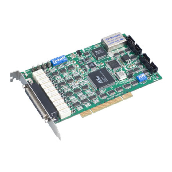
- Page 2 PCI-1727U 12-ch Analog Output Card with Universal PCI User Manual...
- Page 3 No part of this man- ual may be reproduced, copied, translated or transmitted in any form or by any means without the prior written permission of Advantech Co., Ltd. Information provided in this manual is intended to be accurate and reli- able.
- Page 4 Product Warranty (2 years) Advantech warrants to you, the original purchaser, that each of its prod- ucts will be free from defects in materials and workmanship for two years from the date of purchase. This warranty does not apply to any products which have been repaired or...
- Page 5 This product has passed the CE test for environmental specifications when shielded cables are used for external wiring. We recommend the use of shielded cables. This kind of cable is available from Advantech. Please contact your local supplier for ordering information.
- Page 6 Safety Instructions Read these safety instructions carefully. Keep this User's Manual for later reference. Disconnect this equipment from any AC outlet before cleaning. Use a damp cloth. Do not use liquid detergents for cleaning. For plug-in equipment, the power outlet socket must be located near the equipment and must be easily accessible.
- Page 7 The sound pressure level at the operator's position according to IEC 704- 1:1982 is no more than 70 dB (A). DISCLAIMER: This set of instructions is given according to IEC 704-1. Advantech disclaims all responsibility for the accuracy of any statements contained herein. Safety Precaution - Static Electricity Follow these simple precautions to protect yourself from harm and the products from damage.
-
Page 8: Table Of Contents
Chapter 2 Installation ............. 10 Unpacking ............... 10 Driver Installation ............11 Figure 2.1: Advantech Automation Software Setup ..12 Figure 2.2:Different Options for Driver Setup .... 12 Hardware Installation ............13 Device Configuration ............14 Figure 2.3:The Device Manager Dialog Box ....14 Figure 2.4:The Device Setting Dialog Box .... - Page 9 PCI-1727U User Manual viii...
- Page 10 Introduction This chapter contains information on the PCI-1727U and instruction on card con- figuration in order to match your appli- cation and prepare it for installation on your system. Sections include: • Features • Applications • Installations Guide • Software Overview •...
-
Page 11: Chapter 1 Introduction
PCI-1727U is an ideal, economical solution for the applications which require multiple PID control loops. In addition to its analog outputs, PCI-1727U provides 16 TTL DI and 16 TTL DO channels that are easily applied with industrial on/off control applications. -
Page 12: Applications
BoardID The PCI-1727U has a built-in DIP Switch that helps define each card’s ID when multiple PCI-1727U cards have been installed on the same PC chassis. With correct BoardID settings, you can easily identify and access each card during hardware configuration and software programming. -
Page 13: Figure 1.1:Installation Flow Chart
Figure 1.1 provides a concise flow chart to give users a broad picture of the software and hardware installation procedures: Figure 1.1: Installation Flow Chart PCI-1727U User Manual... -
Page 14: Software Overview
1.4 Software Overview Advantech offers a rich set of DLL drivers, third-party driver support and application software to help fully exploit the functions of your PCI-1727U card: • Device Drivers (on the companion CD-ROM) • LabVIEW driver • Advantech ActiveDAQ Pro Programming Choices for DA&C Cards... -
Page 15: Device Driver Programming Roadmap
• C++ Builder For instructions on how to begin programming in each development tool, Advantech offers a Tutorial Chapter in the Device Drivers Manual for your reference. Please refer to the corresponding sections in this chapter on the Device Drivers Manual to begin your programming efforts. You can also look at the example source code provided for each programming tool, since they can get you very well oriented. -
Page 16: Programming With Device Drivers Function Library
1.5.2 Programming with Device Drivers Function Library Advantech Device Drivers offer a rich function library that can be utilized in various application programs. This function library consists of numer- ous APIs that support many development tools, such as Visual C++, Visual Basic, Delphi and C++ Builder. -
Page 17: Wiring Boards
ADAM-3937 - The ADAM-3937 is a 37-pin D-type wiring terminal module for DIN-rail mounting. This terminal module can be easily connected to the Advantech PC-Lab cards and allows easy yet reliable access to individual pin connec- tions for the PCI-1727U card. - Page 18 Installation This chapter contains a package item checklist, proper instructions for unpacking and step-by-step procedures for card installation. Sections include: • Unpacking • Driver Installation • Hardware Installation • Device Configuration...
-
Page 19: Chapter 2 Installation
Chapter 2 Installation 2.1 Unpacking After receiving your PCI-1727U package, please inspect its contents first. The package should contain the following items: • PCI-1727U card • Companion CD-ROM (Device Drivers included) • User Manual The PCI-1727U cards harbor certain electronic components vulnerable to electrostatic discharge (ESD). -
Page 20: Driver Installation
PC or transport it else- where. 2.2 Driver Installation We recommend you install the driver before you plug the PCI-1727U into your system, since this will guarantee a smooth installation process. The Advantech Device Drivers Setup program for the PCI-1727U card is included in the companion CD-ROM that is shipped with your DA&C... -
Page 21: Figure 2.1: Advantech Automation Software Setup
Figure 2.1: Advantech Automation Software Setup 3. First, install the Advantech Device Manager. 4. Select the "Individual Drivers" to install the specific device driver then just follow the installation instructions step by step to complete your device driver installation and setup. -
Page 22: Hardware Installation
4. Touch the metal part on the surface of your computer to neutralize the static electricity that might be on your body. 5. Insert the PCI-1727U card into a PCI slot. Hold the card only by its edges and carefully align it with the slot. Insert the card firmly into place. -
Page 23: Device Configuration
2.4 Device Configuration The Advantech Device Manager Program is a utility that allows you to set up, configure and test your device, and later stores your settings on the system registry. These settings will be used when you call the APIs of Advantech Device Drivers. -
Page 24: Figure 2.4:The Device Setting Dialog Box
Figure 2.4: The Device Setting Dialog Box After your card is properly installed and configured, you can click the ‘Test’ button to test your hardware by using the testing utility. Figure 2.5: Analog Output Test Utility For more detailed information, please refer to Chapter 2 of the Device Drivers Manual. - Page 25 PCI-1727U User Manual...
- Page 26 Signal Connections This chapter provides useful informa- tion about how to connect input and output signals to the PCI-1727U via the I/O connector. Sections include: • Overview • Switch & Jumper Settings • Signal Connections...
-
Page 27: Chapter 3 Signal Connections
A good signal connection can avoid unnecessary and costly dam- age to your PC and other hardware devices. This chapter provides useful information on how to connect input and output signals to the PCI-1727U via the I/O connector. 3.2 Switch & Jumper Settings The PCI-1727U card has two function jumper settings. -
Page 28: Table 3.1:Summary Of Jumper Settings
Table 3.1: Summary of Jumper Settings Jumper Name Function Description Retain last status after hot reset Default configuration Table 3.2: Summary of Jumper Settings Jumper/Switch Setting & Function Description JP2~JP5 Set AO channels to VOLTAGE MODE. JP2~JP5 Set AO channels to CURRENT MODE. -
Page 29: Signal Connections
On: 1, Off: 0 3.3 Signal Connections Pin Assignment The PCI-1727U is equipped with a 37-pin D-type connector, accessible from the rear plate, and two on-board 20-pin insulation displacement con- nectors. All connectors accommodate the same type of flat cable, or can be connected to 37-pin D-type connectors through our PCLD-880 indus- trial wiring kit. - Page 30 Connector 1 (CN1) - Digital Output Connector 2 (CN2) – Digital Input Chapter 3...
- Page 31 Connector 3(CN3) – D/A output PCI-1727U User Manual...
-
Page 32: Table 3.3:I/O Connection Signal Description
Analog ground. Voltage Output Connections The PCI-1727U supports 12 channels of Analog voltage output. There is only one output signal wire for each channel, as the voltage is referenced to the common ground. A standard wiring diagram showing how to con- nect a voltage output channel with a load as shown below. - Page 33 0 to 20 mA Current Output Connections The PCI-1727U provides 12 channels of 0 to 20 mA current output. The current loop utilizes 0 to 5 V (unipolar) voltage output as the driving source. The PCI-1727U's current drive circuit consists of a power FET, and a constant current source.
- Page 34 3. Floating load with the internal 12 V supply Digital Signal Connections The PCI-1727U has 16 digital input and 16 digital output channels. The digital I/O levels are TTL compatible. To transmit or receive digital sig- nals to and from other TTL devices, the connection should be as follows.
- Page 35 Field Wiring Considerations When the PCI-1727U acquires data from outside, noise in the environ- ment might affect the accuracy of your measurements if preventative measures are not taken. The following is helpful to reduce running signal wire interference between signal sources and the PCI-1727U.
- Page 36 Specifications...
-
Page 37: Appendix A Specifications
• Logic0 : 0.8V max • Logic1 : 2.0V min • Input loading : 0.5V@0.4mA max.(low) 2.7V@50µA max(high) Digital Output • Channel : 16 channel • Level : TTL compatible • Logic0 : 0.5V@8mA(sink) • Logic1 : 2.4V @0.4mA (source) PCI-1727U User Manual... - Page 38 Power supply • +5V :250mA typical,500mA max • +12V:150 mA typical,300mA max • -12V:100 mA typical,130mA max General • Connector 37-pin D-type female • Dimension 175×100mm (6.9” ×3.9”) • Operation temperature 0 ~ 50° C (32~149° F) • Storage temperature -20 ~ 60C °...
- Page 39 PCI-1727U User Manual...
- Page 40 Block Diagram...
-
Page 41: Appendix B Block Diagram
PCI BRI DGE Vout D/ A[ 8] I out Vout D/ A[ 9] I out Vout D/ A[ 10] I out Vout D/ A[ 11] I out D/ I [ 15. . 0] D/ O[ 15. . 0] PCI-1727U User Manual... - Page 42 Artisan Technology Group is your source new and certified-used/pre-owned equip SERVICE CENTER REPAIRS WE BUY USED E • FAST SHIPPING AND DELIVERY Experienced engineers and technicians on staff Sell your exce at our full-service, in-house repair center We also offer •...
Need help?
Do you have a question about the PCI-1727U and is the answer not in the manual?
Questions and answers