Table of Contents
Advertisement
Advertisement
Table of Contents

Subscribe to Our Youtube Channel
Related Manuals for Nidek Medical ICE mini


Summary of Contents for Nidek Medical ICE mini
- Page 1 INTELLIGENT BLOCKER ICE mini Model OPERATOR’S MANUAL...
- Page 2 NIDEK CO., LTD. : 34-14, Maehama, Hiroishi-cho, Gamagori, Aichi 443-0038, Japan (Legal Manufacturer) Telephone: (81-533) 67-6611 Facsimile: (81-533) 67-6610 NIDEK CO., LTD : 3F Sumitomo Fudosan Hongo Bldg., 3-22-5, Hongo, (Tokyo Office) Bunkyo-Ku, Tokyo 113-0033, Japan Telephone: (81-3) 5844-2641 Facsimile: (81-3) 5844-2642 NIDEK INCORPORATED : 47651 Westinghouse Drive, Fremont, California 94539, U.
- Page 3 BEFORE USE, READ THIS MANUAL. This operator's manual includes operating procedures, safety precautions and specifications for the Nidek Intelligent Blocker ICE mini. IEC standards are applied in this manual. The cautions for safety and operating procedures must be thoroughly understood before using the instrument.
- Page 4 Use precautions Before Use • Do not use the instrument for other than the intended purpose. CAUTION NIDEK is not responsible for accidents or malfunctions caused by careless use. • Never disassemble nor touch the inside of the instrument. This may result in electric shock or malfunction. •...
- Page 5 During Use • Connect the cable to the interface connector securely, maintaining the correct CAUTION orientation of the cable connector. Data transmission is not performed properly. • In the event of smoke or strange odors, immediately turn off the instrument and disconnect the power plug from the outlet.
- Page 6 After Use • Do not yank the power cord to disconnect it from a wall outlet but hold the plug. CAUTION This can damage the metal core of the cord and may result in fire, short circuit or elec- tric shock. •...
- Page 7 [Operating area and maintenance work area] Maintenance work area About 500 mm About 500 mm Operating area About 1000 mm Disposal • Follow the local ordinances and recycling regulations regarding disposal or recycling CAUTION of the components. It is recommended to commission the disposal to a designated industrial waste disposal contractor.
-
Page 9: Table Of Contents
Table of Contents 1. BEFORE USE ........1 1.1 Outline of the Blocker . - Page 10 Setting the ICE mini ........
-
Page 11: Before Use
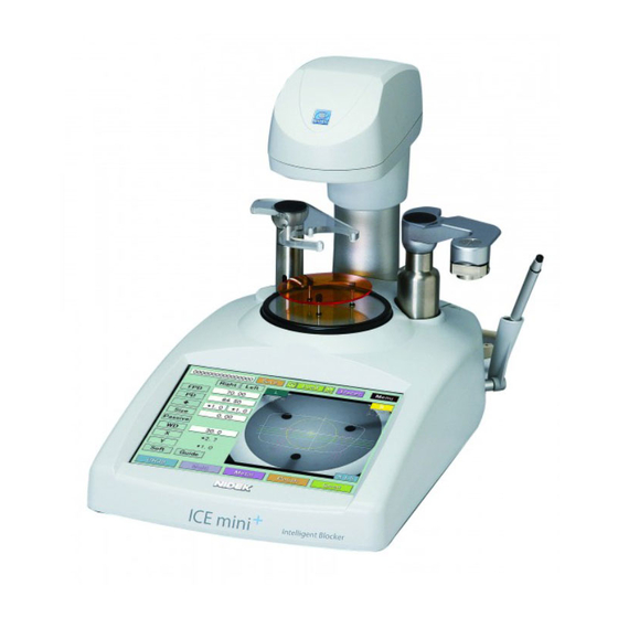
The NIDEK intelligent blocker, ICE mini, blocks the lens with a lens cup. In the Blocker/LE and Mini LAB systems, the ICE mini, when connected to a tracer equipped lens edger, loads shape data and displays the data on the LCD touch screen. In the Blocker LAB, VCA (Preset), and VCA (Auto) systems, the ICE mini loads JOB data and blocks the lens. -
Page 12: Configuration
BEFORE USE: Configuration Configuration Front view Lens clamp Blocking arm Lens table Cup holder LCD touch screen Touch pen holder USB memory slot Lens clamp Holds the lens convex side level. Lower the lens clamp Lift it once and lower it gently. Lift the lens clamp Lift it until it clicks. - Page 13 BEFORE USE: Configuration LCD screen 8.4-inch color LCD touch screen. Used to display or enter various items. Blocking arm Blocks the lens after the arm head is rotated on the lens holder and pushed down. Cup holder The lens cup is attached here. Insert the lens cup aligning the top mark with the circle on the cup Circle indicating the holder.
- Page 14 Fuse holder Inlet BARCODE connector TRACER connector Power switch Turns on power to the ICE mini. Fuse holder Contains two fuses (T 1 A 250 V). Inlet This is for the power cord. This is integrated with the fuse holder.
- Page 15 Used to connect the tracer when the Mini LAB system is used. Ethernet: Standards on wirings, and access to the wirings to allow mutual accessing of various information processing terminals to the LAN. The ICE mini exchanges data through the 10BASE-T.
-
Page 16: Displays
BEFORE USE: Displays Displays 1.3.1 Blocker/LE and Mini LAB systems [Layout screen (Other than Multi)] Block the lens aligning to the lens markings or eye point mark of the progressive lens. JOB#/PTN# Frame pupil distance Pupillary distance Optical center height Size Layout mode X inside value... - Page 17 BEFORE USE: Displays Optical center height ( Indicates the optical center height from the frame (boxing) center, which is entered manually. Range: [-15.0 to +15.0 mm (in increments of 0.1 mm)] and BT can also be entered for the optical center height. Size Indicates the enlarged or reduced lateral size from a loaded lens shape.
- Page 18 Displays data measured by the tracer on the LCD touch screen. MENU Displays the pop-up menu that includes the two options of initial screen memorization and shape change. When this button is pressed for about three seconds, the Parameter 1 screen for ICE mini customizing appears. Right/Left indication Specifies the lens data for the left-eye or right-eye.
- Page 19 BEFORE USE: Displays Alignment scale This scale serves as a guide during alignment of the markings on the lens. The optical center of the lens must be aligned to the scale center. Position the lens so that the middle marking on the lens is aligned with the center of this alignment scale or the markings become parallel to the horizontal scales.
- Page 20 BEFORE USE: Displays [Layout screen (Multi)] Block the lens at the frame center aligning with the lens segment. * Descriptions for items not listed below are the same as for those in Other than Multi. Segment mark Indicates the width of a segment. (Unit: mm) Enter the WD depending on the segment size for easy alignment.
-
Page 21: Blocker Lab System
1.3.2 Blocker LAB system In the Blocker LAB system, the ICE mini loads the data specified by JOB# from the server PC, changes the layout, and blocks the lens. The data is sent to the server PC after blocking. The memory function of the ICE mini is not available. Therefore, the indications and buttons for saving or loading data to the memory are not displayed. -
Page 22: Vca (Preset) And Vca (Auto) Systems
1.3.3 VCA (Preset) and VCA (Auto) systems In the VCA (Preset) and VCA (Auto) systems, the ICE mini loads the data specified by JOB# from the server PC and blocks the lens without changing the layout. The ICE mini functions just as a blocker terminal. -
Page 23: Labels
BEFORE USE: Labels Labels Cautionary labels are provided on the ICE mini. If labels are curling up or characters fading and becoming barely legible, contact NIDEK or your authorized distributor. Indicates that caution must be taken. Refer to the operator's manual before use. - Page 24 BEFORE USE: Labels [Side and rear views]...
-
Page 25: Checking Contents
BEFORE USE: Checking Contents [Side view] Checking Contents Unpack the contents from the shipping carton and check them. The following are included in the standard configuration. • Main body • Touch pen • Communication cable • Power cord • Frame change holder •... -
Page 26: Before First Use
• The electrical outlet must have a grounding terminal. CAUTION Electric shock or fire may occur in the event of malfunction or power leakage. Turn the power switch ON ( The initial screen is displayed on the LCD touch screen and the ICE mini is initialized. ICE mini... - Page 27 BEFORE USE: Before First Use Check that the layout screen is displayed after the ICE mini is initialized. This is all you have to do before use. • Set the parameters to suit your needs or preferences. See “4.1 Parameter Settings” (Page 63) for the parameters and their setting methods.
- Page 28 BEFORE USE: Before First Use...
-
Page 29: Operating Procedures
A branch outlet that is concurrently used with other instruments may cause overheating and fire. Make sure that the cables from the connected instruments are securely connected to the ICE mini, and the power for each instrument is turned on. See “4.2 Connection” (Page 67) for the connecting method. - Page 30 OPERATING PROCEDURES: Start-up 2) The layout display appears. The ICE mini is now ready for use. Numeric keypad display position The numeric keypad display position can be moved with the Move button ( Move the numeric keypad by dragging it while pressing the Move button when the keypad overlays any display.
-
Page 31: Operating Procedures
Tracing in the Blocker/LE system: 1) Trace the lens frames with the lens edger connected to the ICE mini. 2) The data is transferred to the ICE mini automatically after tracing. The data is displayed on the layout screen. Tracing in the Mini LAB system: 1) Enter the JOB#. - Page 32 OPERATING PROCEDURES: Operating Procedures Enter the lens layout data. See “2.3.2 Entering lens layout data for lenses other than Multi” (Page 37) or “2.3.3 Entering lens layout data for bifocal lenses” (Page 44) for the lens layout data entry procedure. When blocking the single vision lens, mark it using a lensmeter according to prescription.
- Page 33 OPERATING PROCEDURES: Operating Procedures Place the lens on the lens support with the convex side up. Hold the lens with the lens clamp. 1) Rotate the lens clamp while lifting it over the lens. 2) Slightly raise the lens clamp and lower it slowly while holding it by hand.
- Page 34 OPERATING PROCEDURES: Operating Procedures When the lens type is other than Multi: When the lens type is Multi: Align the middle marking or eye point mark for Align the segment with the segment mark. far vision with the center of the alignment scale. Block the lens.
- Page 35 OPERATING PROCEDURES: Operating Procedures 4) Lightly press the blocking arm to release it. Rotate it to the stand-by position. 5) Raise the lens clamp at the top position and rotate it to the stand-by position while lifting it. 6) Take the blocked lens off. Save the JOB data as necessary.
-
Page 36: Blocker Lab System
2.2.2 Blocker LAB system In the Blocker LAB system, the ICE mini loads the data specified by JOB# from the server PC, changes the layout, and blocks the lens. The data is sent to the server PC after blocking. The memory function of the ICE mini is not available. - Page 37 OPERATING PROCEDURES: Operating Procedures Press the Send button when the lens layout data is changed. The JOB data is transferred to the server PC. Store the blocked lens in a tray etc. with the JOB# on it. Clearly mark the left- or right-eye lens on the tray etc. when storing the lens. To block the other lenses subsequently, enter the JOB# to load the data.
-
Page 38: Vca (Preset) And Vca (Auto) Systems
2.2.3 VCA (Preset) and VCA (Auto) systems In the VCA (Preset) and VCA (Auto) systems, the ICE mini loads the data specified by JOB# from the server PC and blocks the lens without changing the layout. The memory function of the ICE mini is not available. -
Page 39: Saving Data
OPERATING PROCEDURES: Operating Procedures 2.2.4 Saving Data Save JOB data into the internal memory. Select the data is saved as JOB or PTN (registered shape) depending on the numbering method. • When the data is saved as PTN (registered shape) with the PTN# including alphanumeric characters, set the Input Interface (JOB/PTN Code) to KEYPAD. -
Page 40: Blocking With Frame Change Holder
OPERATING PROCEDURES: Operating Procedures 2.2.5 Blocking with frame change holder Use the provided holder when the lens can not be held with the three pins on the lens table because the lens diameter is small as for when lenses are being reused in different frames. Place the frame change holder on the center of the lens table. -
Page 41: Blocking With Sheet
OPERATING PROCEDURES: Operating Procedures 2.2.6 Blocking with sheet Use the provided sheet to block the positive power or bifocal lens when the lens shape and/or segment are not seen clearly. The patterns on the sheet enhance the lens shape and Patterns for lens shape segment. -
Page 42: Setting Processing Conditions And Entering Lens Layout Data
OPERATING PROCEDURES: Setting Processing Conditions and Entering Lens Layout Data Setting Processing Conditions and Entering Lens Layout Data Load traced data before setting processing conditions and entering lens layout data. Lens layout data Processing conditions 2.3.1 Setting processing conditions As processing conditions, set the lens material, lens type, frame type, whether or not to polish lenses, and whether or not to safety bevel lenses. - Page 43 OPERATING PROCEDURES: Setting Processing Conditions and Entering Lens Layout Data • Lens type Select the lens type. Each press of this button switches the lens type between Multi and other than Multi. • Multi...Shown in white (high-lightened) • Other than Multi...Shown in gray •...
- Page 44 • Setting this mode applies the guided beveling automatically during lens processing. This prevents the lens from being processed in auto mode. • For guided beveling in the ICE mini, the software version of the lens edger must be compatible.
- Page 45 OPERATING PROCEDURES: Setting Processing Conditions and Entering Lens Layout Data • Safety beveling Select whether the lens edge is safety-beveled. The selectable options depend on the connected lens edger. When the Polish/S.B Setting parameter is set to LE: Each press of the S.F.B. button switches safety beveling ON and OFF. •...
- Page 46 • Soft processing mode is on...The Soft button is pressed. • Soft processing mode is off...The Soft button is not pressed. • For soft processing in the ICE mini, the software version of the lens edger must be compatible. • Setting this mode applies the soft processing automatically during lens processing.
-
Page 47: Entering Lens Layout Data For Lenses Other Than Multi
OPERATING PROCEDURES: Setting Processing Conditions and Entering Lens Layout Data 2.3.2 Entering lens layout data for lenses other than Multi Block the lens aligning to the lens markings or eye point mark of the progressive lens when the lens type is other than Multi. According to prescription, enter lens layout data (FPD, PD, and optical center height). - Page 48 OPERATING PROCEDURES: Setting Processing Conditions and Entering Lens Layout Data The DBL (width between the nasal ends of the left and right frames) can also be entered instead of the FPD. Pressing the FPD button displays the pup-up menu. Press the DBL button to enter the DBL value.
- Page 49 OPERATING PROCEDURES: Setting Processing Conditions and Entering Lens Layout Data 3) Optical center height Enter the optical center height for the left- and right-eye lenses respectively. Press the (or PD , BT ) numeric button to display the numeric keypad. Enter any value and press the Ent button.
- Page 50 OPERATING PROCEDURES: Setting Processing Conditions and Entering Lens Layout Data 4) Size (Enlarged or reduced lateral size of a lens shape) Enter arbitrary value in the Size field if necessary. Press the Size numeric button to display the numeric keypad. Enter any value and press the Ent but- ton.
- Page 51 OPERATING PROCEDURES: Setting Processing Conditions and Entering Lens Layout Data Changes in the cup mark shape according to the layout setting When the lens shape contacts the circle of the cup mark, the circle changes into an oblate ellipse. The oblate ellipse shows the minimum lens size with a lens cup for half-eye lens.
- Page 52 OPERATING PROCEDURES: Setting Processing Conditions and Entering Lens Layout Data Minimum lens diameter for processing with the lens edger Minimum lens Minimum horizontal Minimum vertical Lens edger diameter for the length for lens to be length for lens to be standard lens cup processed processed...
- Page 53 OPERATING PROCEDURES: Setting Processing Conditions and Entering Lens Layout Data Setting alignment scale The height of the horizontally long ellipse and the spacing between the horizontal lines of the alignment scale can be changed by the corresponding parameters. See “4.1 Parameter Settings” (Page 63) for the parameter setting procedure. Alignment scale: (A in the figure) Select the spacing between horizontal lines: 0 mm, 1.0 mm, 2.0 mm, or 3.0 mm.
-
Page 54: Entering Lens Layout Data For Bifocal Lenses
OPERATING PROCEDURES: Setting Processing Conditions and Entering Lens Layout Data 2.3.3 Entering lens layout data for bifocal lenses Block the bifocal lens aligning to the segment base point (top line center of segment). According to prescription, enter lens layout data (FPD, near PD, and optical center height). Select the passive as the layout mode. - Page 55 OPERATING PROCEDURES: Setting Processing Conditions and Entering Lens Layout Data Select either of the following. Enter the distance from the center point on the top line of the segment straight down to the point on the lens shape. Enter the height from the point level with the center of the segment on the top line straight down to the lowest point on the...
-
Page 56: Shape Change Function
OPERATING PROCEDURES: Shape Change Function Shape Change Function This function changes the loaded lens shape data into the desired shape. There are two entering methods for changes. • Changes in shape by changing the horizontal and vertical numeric values. • Changes in shape by dragging the lens shape with the touch pen. There is also a method to determine the area that is not to be changed and other area that can be changed. - Page 57 OPERATING PROCEDURES: Shape Change Function As necessary, specify the area that is not to be changed in shape. Shape Editor 1) Press the Fix Area button to switch to fixed area specification mode. Numeric values disappear and a section of the lens shape is displayed in yellow.
- Page 58 OPERATING PROCEDURES: Shape Change Function Shape change with numeric values 1) Select a step to be changed from the pop- up menu displayed by pressing the Step Shape Editor button. Select the desired step button from Tenkey, 0.10, 0.25, or 0.50. 2) Press a numeric value to be changed.
- Page 59 OPERATING PROCEDURES: Shape Change Function Shape change by dragging 1) Click the area to be changed with the touch pen and change it to the desired Shape Editor shape. When dragging starts, the numeric values dis- appear and the changed shape is displayed in red.
- Page 60 OPERATING PROCEDURES: Shape Change Function Buttons on the Shape Editor screen Step Increases or decreases with the +/- buttons. Undo Undoes the last change (undo function). Up to three changes can be restored. Redo Restores the change by undo (redo function). Undo operation can be canceled.
-
Page 61: Grooving Settings
The grooving data is transferred to the lens edger together with the normal processing data; it is unnecessary to set the grooving specifications in the lens edger. • The setting is possible only when the ICE mini is connected to equipment having the grooving function in the Mini LAB system (ME-1000 or SE-9090 Express/AHM-1000 system). - Page 62 OPERATING PROCEDURES: Grooving Settings • Curve 1) Press the Curve button. The pop-up menu is displayed. 2) Select the desired curve from the menu. Auto Computer-calculated curve Guide Sets guided grooving to be automatic when processing. Manually enter the desired curve. Curve Pressing the numeric button displays the numeric keypad.
- Page 63 In the ICE mini, the groove specifications are set without measuring the lens curve. Therefore, the set specifications may make the groove to be off the lens edge.
-
Page 64: Daily Checks
OPERATING PROCEDURES: Daily Checks Daily Checks Check the following before and after every use each day. It is recommended that a checklist is prepared and the check results are recorded. Check before use 1) Are there any appearant deformations or dirt which might interfere with proper operation? Especially confirm that there are no foreign substances or dirt on the lens table. -
Page 65: Initial Layout Screen Save Function
OPERATING PROCEDURES: Initial Layout Screen Save Function Initial Layout Screen Save Function This function sets the items on the layout screen displayed when the power is turned on. When the factory settings on the layout display differ from those ordinary used, it is possible to change and save the items to be displayed on the initial layout screen upon system activation. - Page 66 OPERATING PROCEDURES: Initial Layout Screen Save Function Save the settings. 1) Press the MENU button. The pop-up menu is displayed. 2) Press the Mem. Screen button. The "Do you want to memorize initial screen?" message, which ask the operator whether or not to save the settings on the screen as default, appears.
-
Page 67: Maintenance
MAINTENANCE Troubleshooting In the event that the blocker does not work correctly, correct the problem according to the following table before contacting NIDEK or your authorized distributor. Symptom Actions • Make sure that the power cord is properly connected. • Make sure that the voltage applied to the outlet is within the range specified. The blocker does not work at all. -
Page 68: Replacing Fuses
MAINTENANCE: Replacing Fuses Replacing Fuses If the system is not started even though the power switch is turned on, the fuses may be blown. Replace the fuses with spare ones. • Be sure to turn off the power and disconnect the power cord from the outlet before CAUTION replacing the fuses. -
Page 69: Setting Time And Date
MAINTENANCE: Setting Time and Date Setting Time and Date Display the Parameter 1 screen. Press the MENU button on the layout screen for about three seconds until beep sounds are audible. Press the >> button twice to display the Clock screen. -
Page 70: Adjusting Cup Holder
MAINTENANCE: Adjusting Cup Holder Adjusting Cup Holder When the plunger inside the cup holder is loosen or worn out, the cup holder may not hold the lens cup securely. In such a case, insert the hexagonal wrench into the hole at the front of the cup holder and turn the plunger so that the lens cup is fixed securely and it is detached or inserted smoothly. -
Page 71: List Of Replacement Parts
MAINTENANCE: List of Replacement Parts List of Replacement Parts Part name Part number Note Fuse 80402-02155 T 1 A 250 V 5 × 20 mm * After replacing consumables, restock them. - Page 72 MAINTENANCE: List of Replacement Parts...
-
Page 73: Connection And Settings
CONNECTION AND SETTINGS Parameter Settings The parameters can be changed according to the needs of the operator. Display the Parameter 1 screen. Press the MENU button on the layout screen for about three seconds until beep sounds are audible. Press the button of the desired parameter to select and change the setting. The parameter setting is shown next to the button. - Page 74 Blocker/LE 9000SX (maximum of two units) Mini LAB Small- or middle-scale system where the ICE mini acts as a data server System connecting the ICE mini and server PC via a LAN port. Blocker LAB The communication protocol is NIDEK-LAN.
- Page 75 CONNECTION AND SETTINGS: Parameter Settings 2) RS-232C Baudrate: 9600, 38400 Factory setting: 38400 Sets the communication speed (baud rate) for data communication using the EDGER 1 and EDGER 2 ports. 3) Cup Mode: STD, Pliable, Mini Factory setting: STD Sets the lens cup to be used. Selecting STD makes the following two functions available: •...
- Page 76 CONNECTION AND SETTINGS: Parameter Settings [Parameter description: Parameter 2 screen] 10) Layout Preset: -5.0 to 5.0mm Factory setting: 2.0 mm Sets the default optical center height. Set any value from -5.0 to 5.0 mm (in increments of 0.1 mm). 11) Alignment Scale: 0.0, 1.0, 2.0, 3.0 Factory setting: 2.0 Selects the spacing between horizontal lines of the alignment scale, displayed on the layout screen when the lens type is other than Multi, from 0, 1.0 mm, 2.0 mm, and 3.0 mm.
-
Page 77: Connection
4.2.1 Connection samples Connect a lens edger and/or LAN cable etc. to the ICE mini. • Confirm that all instruments are turned off before connecting them to the ICE mini. CAUTION Blocker/LE system The smallest system comprised of the ICE mini connected directly to the LE-9000SX/LX (maximum of two units). - Page 78 CONNECTION AND SETTINGS: Connection Mini LAB system In this small- or middle-scale system, the ICE mini serves as a data server. Tracing is performed with the LT-900 connected to the ICE mini. When connecting two lens edgers at the maximum:...
- Page 79 CONNECTION AND SETTINGS: Connection Method of connection to the ICE mini: LAN-RS232C Converter LE-9000EX LAN cable LAN port EDGER 1 connector RS-232C cable EDGER 2 connector BARCODE TRACER connector connector LE-9000EX * Connects to the RS- RS-232C cable 232C connector.
- Page 80 CONNECTION AND SETTINGS: Connection Blocker LAB system It is the system connecting the ICE mini and server PC via a LAN port. The communication protocol is NIDEK-LAN. LAN cable LAN-RS232C Converter FA-11 RS-232C cable Barcode scanner (option) LE-9000EX SE-9090 Server PC...
- Page 81 CONNECTION AND SETTINGS: Connection Method of connection to the ICE mini: LAN (Ethernet) LAN cable LAN port BARCODE connector Barcode scanner (option)
- Page 82 CONNECTION AND SETTINGS: Connection VCA (Preset) and VCA (Auto) systems The ICE mini is connected to the server PC with the RS-232 cable via the Edger 1 port. The communication protocol of each system is VCA. RS-232C cable Server PC...
-
Page 83: Setting The Ice Mini
*4: Never change the factory setting of Mac Address that had been set uniquely for each individual ICE mini before shipment. *5: Set these parameters in accordance with the network to which the ICE mini is connected. *6: Set the LAN-RS232C converter for connecting to the PC when other edgers are connected with the LAN-RS232C converter in the same network and TCP is selected. -
Page 84: Setting Connected Instruments
CONNECTION AND SETTINGS: Connection 4.2.3 Setting connected instruments Set the external interface depending on the system configuration including the ICE mini: Settings of the LE-9000 Blocker LAB Parameter Blocker/LE Mini LAB Ext. interface BK/LE Layout memory Exec Exec Exec SERVER No. - Page 85 Blocker LAB port is used) Ext. interface Communication port/ RS232C protocol Select the same baud Baud rate – rate as the ICE mini. Never change the MAC address — factory setting. * Set the parameter uniquely for each IP address —...
- Page 86 CONNECTION AND SETTINGS: Connection Settings of the LT-900 To directly connect the LT-900 to the ICE mini, connect the LT-900 to the TRACER connec- tor of the ICE mini. Parameter Mini LAB Setting - Communication Select the same baud rate as Baud Rate the LT-900.
-
Page 87: Specifications And Accessories
SPECIFICATIONS AND ACCESSORIES Specifications Blocking function • Method Imaging of projected image • Maximum lens diameter φ80 mm • Blocking method Manual • Blocking precision φ0.5 mm or less Position Axis angle ±0.5° or less Range of data for lens layout •... - Page 88 SPECIFICATIONS AND ACCESSORIES: Specifications Display • 8.4-inch SVGA color LCD (touch screen) Other function • Screen saving function • Update function • Memory function • Shape change function Dimensions, weight, etc. • Dimensions 230 (W) x 367 (D) x 392 (H) mm * Excluding options and protrusions •...
-
Page 89: Standard Configuration
SPECIFICATIONS AND ACCESSORIES: Standard Configuration Standard Configuration 5.2.1 Standard accessories • Touch pen 1 unit • Communication cable 1 unit • Power cord 1 unit • Frame change holder 1 unit • Sheet 1 unit • Spare fuse 2 units •... - Page 90 SPECIFICATIONS AND ACCESSORIES: Standard Configuration...
-
Page 91: Index
INDEX Lens clamp ........2 Numerics Lens material . - Page 92 INDEX: X inside value ........7 Y inside value ........7...
Need help?
Do you have a question about the ICE mini and is the answer not in the manual?
Questions and answers