
Related Manuals for Nidek Medical RS-3000


Summary of Contents for Nidek Medical RS-3000
- Page 1 OPTICAL COHERENCE TOMOGRAPHY RS-3000 Model SERVICE MANUAL 2009.05 Pages in total:144 XSO1**RDA002A...
- Page 2 NIDEK CO., LTD. : 34-14, Maehama, Hiroishi-cho, Gamagori, Aichi 443-0038, Japan (Manufacturer) Telephone: 81-533- 67-6611 Facsimile: 81-533-67-6610 NIDEK CO., LTD : 3F Sumitomo Fudosan Hongo Bldg., 3-22-5, Hongo, (Tokyo Office) Bunkyo-Ku, Tokyo 113-0033, Japan Telephone: 81-3-5844-2641 Facsimile: 81-3-5844-2642 NIDEK INCORPORATED : 47651 Westinghouse Drive, Fremont, California 94539, U.
-
Page 3: Table Of Contents
XSO1**RDA002A Table of Contents 1. INTRODUCTION ........1 2. - Page 4 5 . 4 . 3 RS-3000 Capture is not activated ......25 5 . 4 . 4 RS3K Capture error appears on LCD monitor of PC .
- Page 5 XSO1**RDA002A 6 . 1 . 4 Chinrest ASSY front cover (10701-M502) ..... 43 6 . 1 . 5 Front cover (10701-M701) ....... . . 44 6 .
- Page 6 8 . 6 . 2 Error log file of RS-3000 Capture ......87 8 .
- Page 7 XSO1**RDA002A 9 . 2 . 2 Main body..........98 9 .
- Page 8 XSO1**RDA002A This page is intentionally left blank...
-
Page 9: Introduction
XSO1**RDA002A 1 INTRODUCTION This Service Manual is for the NIDEK OPTICAL COHERENCE TOMOGRAPHY, RS-3000. For correct service, thorough understanding of the contents in this manual is required prior to the service. Refer to the Operator’s Manual and Parts List for the RS-3000. - Page 10 XSO1**RDA002A This page is intentionally left blank...
-
Page 11: Safety Precautions
XSO1**RDA002A 2 SAFETY PRECAUTIONS 1 . General precautions 1 ) Servicing must be performed by NIDEK service persons or other qualified personnel. 2 ) In case the system cannot be repaired by the procedures described in this manual, please report the serial number of the system and details of the symptom or symp- toms. - Page 12 XSO1**RDA002A 3 . Adjustment precautions 1 ) Confirm that the following conditions are met before installation. a . A place which is level and stable without vibration and shock b . No exposure to direct sunlight or ultraviolet rays c . A place with minimal external light source d .
-
Page 13: Specifications
XSO1**RDA002A 3 SPECIFICATIONS 1 . Specifications 1 ) Measurement principle SLO image: Confocal laser scanning method (refraction) OCT image: Spectral OCT (spectral domain OCT) Anterior eye observation image: CCD 2 ) Source wavelength SLO: 785 nm OCT: 880 nm Internal fixation target: 635 nm 3 ) Optical resolution SLO: 25 µm (XY direction) OCT: 20 µm (XY direction) 7 µm (Z direction, eye interior) - Page 14 XSO1**RDA002A This page is intentionally left blank...
-
Page 15: Troubleshooting
XSO1**RDA002A 4 TROUBLESHOOTING Turn on power to the isolation transformer. Does the pilot lamp of the isolation transformer light 5.1 Pilot Lamp of Isolation Transformer does not Light Up Turn on power to the main body. Does the main 5.2 Main Body does not Start Properly body start properly? Is the anterior eye displayed? 5.3 Anterior Eye is not Displayed... - Page 16 XSO1**RDA002A Does the external fixation target light up? 5.8 External Fixation Target does not Light Up Does the internal fixation target light up? 5.9 Internal Fixation Target does not Light Up Does the hand light go on? 5.10 Hand Light does not Go On Can image capture be performed? 5.11 Images cannot be Captured Can printout be performed properly?
-
Page 17: Subtroubleshooting
XSO1**RDA002A 5 SUBTROUBLESHOOTING 5.1 Pilot Lamp of Isolation Transformer does not Light Up Is the power supply voltage proper? Use the wall outlet that supplies proper voltage. Are there any breaks in the power cord of the Replace the power cord of the isolation transformer isolation transformer? (see 9.3). -
Page 18: Main Body Does Not Start Properly
XSO1**RDA002A 5.2 Main Body does not Start Properly Turn on power to the main body. Does the pilot 5.2.1 Pilot lamp of main body does not light up lamp of the main body light up? Does the startup screen appear on the LCD 5.2.2 Startup screen does not appear on LCD monitor of the main body? monitor of main body... -
Page 19: Pilot Lamp Of Main Body Does Not Light Up
XSO1**RDA002A 5.2.1 Pilot lamp of main body does not light up Are the fuses of the main body blown? Replace the fuses of the main body (see 7.1.3.5). Are there any breaks in the power cord of the main Replace the ULHP grade power cord (80511- body (ULHP grade power cord [80511-00038])? 00038) (see 9.3). -
Page 20: Startup Screen Does Not Appear On Lcd Monitor Of Main Body
XSO1**RDA002A 5.2.2 Startup screen does not appear on LCD monitor of main body Does the error beep sound (continuously 10 times) and the function indicator of the operation panel 5.2.4.8 ERROR: 008 (LCD Backlight) blink in blue and white alternately? Is the voltage between each TP and GND of the power filter board (10701-BA06) as below? Between TP1 and GND: +24 V... -
Page 21: Voltage Between Each Tp And Gnd Of Power Filter Board (10701-Ba06) Is Abnormal
XSO1**RDA002A 5.2.3 Voltage between each TP and GND of power filter board (10701-BA06) is abnormal Replace the power filter board (10701-BA06) (see 7.1.2.4). Is the problem resolved? Replace the main body (see 7.1.1.1). -
Page 22: Error Message Appears On Lcd Monitor Of Main Body
XSO1**RDA002A 5.2.4 Error message appears on LCD monitor of main body 5.2.4.1 ERROR: 001 (EEPROM data) Replace the main body (see 7.1.1.1). 5.2.4.2 ERROR: 002 (Connection with PC software) Are the following cables connected properly? Camera link cable (10701-E023) Connect the cables properly. CAPTRG cable (10701-EA05) Replace the camera link cable (10701-E023) (see 9.3). -
Page 23: Error: 003 (Optical Axis Adjustment)
XSO1**RDA002A Replace the capture board (OCT) (10701-BA20) (see 7.3.2). Is the problem resolved? Replace the PC (see 7.3.1). Is the problem resolved? Replace the main body (see 7.1.1.1). 5.2.4.3 ERROR: 003 (Optical axis adjustment) Replace the main body (see 7.1.1.1). 5.2.4.4 ERROR: 004 (Body cover open) Check the attachment of the inner covers. -
Page 24: Error: 005 (Body Cover Dip Switch)
XSO1**RDA002A 5.2.4.5 ERROR: 005 (Body cover DIP switch) Is SW1 on the sub-control board (10701-BA02) set Set SW1 on the sub-control board (10701-BA02) to to the OFF position? the OFF position. Replace the main body (see 7.1.1.1). 5.2.4.6 ERROR: 006 (Base cover) Replace the main body (see 7.1.1.1). -
Page 25: Error: 011 (Spectrometer Motor Overrun)
XSO1**RDA002A 5.2.4.9 ERROR: 011 (Spectrometer motor overrun) Replace the main body (see 7.1.1.1). 5.2.4.10 ERROR: 012 (Spectrometer motor stop) Replace the main body (see 7.1.1.1). 5.2.4.11 ERROR: 013 (OPL motor overrun) Replace the main body (see 7.1.1.1). 5.2.4.12 ERROR: 014 (OPL motor stop) Replace the main body (see 7.1.1.1). -
Page 26: Error: 018 (Up/Down Motor)
XSO1**RDA002A 5.2.4.16 ERROR: 018 (Up/Down motor) Are there any breaks in the U/B motor cable Replace the main body (see 7.1.1.1). (10701-EA42)? Replace the UDM DRV board (10701-BA04) (see 7.1.2.3). Is the problem resolved? Are there any breaks in UDM DRV cable (10701- Replace UDM DRV cable (10701-EA34) (see 9.3). -
Page 27: Error: 021 (Oct X Galvano Driver)
XSO1**RDA002A 5.2.4.17 ERROR: 021 (OCT X galvano driver) Replace the main body (see 7.1.1.1). 5.2.4.18 ERROR: 022 (OCT Y galvano driver) Replace the main body (see 7.1.1.1). 5.2.4.19 ERROR: 023 (OCT galvano mirror) Replace the main body (see 7.1.1.1). 5.2.4.20 ERROR: 024 (OCT SLD Replace the main body (see 7.1.1.1). -
Page 28: Error: 029 (Oct Galvano Synchronization)
XSO1**RDA002A 5.2.4.25 ERROR: 029 (OCT galvano synchronization) Does the image capture application in the PC Activate the image capture application again. freeze? Check the connection of the CAPTRG cable (10701-EA05) (see 9.3). Is the problem resolved? Replace the CAPTRG cable (10701-EA05) (see 9.3). -
Page 29: Error: 031 (Slo Galvano Driver)
XSO1**RDA002A Replace the PC (see 7.3.1). Is the problem resolved? Replace the main body (see 7.1.1.1). 5.2.4.26 ERROR: 031 (SLO galvano driver) Replace the main body (see 7.1.1.1). 5.2.4.27 ERROR: 032 (SLO galvano mirror) Replace the main body (see 7.1.1.1). 5.2.4.28 ERROR: 033 (SLO polygon mirror) Replace the main body (see 7.1.1.1). -
Page 30: Anterior Eye Is Not Displayed
XSO1**RDA002A 5.3 Anterior Eye is not Displayed Is the anterior eye illumination lit (see 8.2)? 5.3.1 Anterior eye illumination is not lit Are there any breaks in the observe CCD cable Replace the observe CCD cable (10701-EA31) (10701-EA19)? (see 9.3). Replace the main board (10701-BA01) (see 7.1.2.1). -
Page 31: Pc Does Not Start Properly
Is Windows XP activated? 5.4.2 OS is not activated properly Is RS-3000 Capture activated? 5.4.3 RS-3000 Capture is not activated Does any error message appear on the LCD 5.4.4 RS3K Capture error appears on LCD monitor monitor of the PC? -
Page 32: Pc Cannot Be Turned On
XSO1**RDA002A 5.4.1 PC cannot be turned on Is the power switch of the PC monitor (10701- Turn on the power switch of the PC monitor E013) turned on? (10701-E013). Is the power switch on the rear of the PC turned Turn on the power switch on the rear of the PC. -
Page 33: Os Is Not Activated Properly
Is the problem resolved? Replace the system disk (10701-E102) (see 7.3.7). Is the problem resolved? Replace the PC (see 7.3.1). 5.4.3 RS-3000 Capture is not activated Replace the system disk (10701-E102) (see 7.3.7). Is the problem resolved? Replace the PC (see 7.3.1). -
Page 34: Rs3K Capture Error Appears On Lcd Monitor Of Pc
XSO1**RDA002A 5.4.4 RS3K Capture error appears on LCD monitor of PC 5.4.4.1 ERROR: 1001 (Connection with DB software) Replace the PC (see 7.3.1). 5.4.4.2 ERROR: 1002 (SLO capture board) Reinsert the capture board (SLO) (10701-BA20). Is the problem resolved? Are the settings of SWs on the capture board (SLO) (10701-BA20) as below? SW1-1 ON Set the SWs (see 8.3.1). -
Page 35: Error: 1003 (Oct Capture Board)
XSO1**RDA002A 5.4.4.3 ERROR: 1003 (OCT capture board) Reinsert the capture board (OCT) (10701-BA20). Is the problem resolved? Are the settings of SWs on the capture board (OCT) (10701-BA20) as below? SW1-1 OFF Set the SWs (see 8.3.1). SW1-2 ON SW1-3 OFF SW1-4 OFF Replace the capture board (OCT) (10701-BA20) (see 7.3.2). -
Page 36: Error: 1012 (Trigger Cable [Input])
XSO1**RDA002A 5.4.4.6 ERROR: 1012 (Trigger cable [input]) Is the CAPTRG cable (10701-EA05) connected Connect the CAPTRG cable (10701-EA05) properly (see 9.3)? properly. Reinsert the capture board (OCT) (10701-BA20). Is the problem resolved? Replace the CAPTRG cable (10701-EA05) (see 9.3). Is the problem resolved? Replace the capture board (OCT) (10701-BA20) (see 7.3.2). -
Page 37: Error: 1014 (Connection With Ccd Camera)
XSO1**RDA002A 5.4.4.8 ERROR: 1014 (Connection with CCD camera) Is the camera link cable (10701-E023) connected Connect the camera link cable (10701-E023) properly? properly. Reinsert the capture board (OCT) (10701-BA20). Is the problem resolved? Replace the camera link cable (10701-E023) (see 9.3). -
Page 38: Image Capturing Unit Does Not Move Smoothly Along Base Unit
XSO1**RDA002A 5.5 Image Capturing Unit does not Move Smoothly along Base Unit Clean the sliding plate (32105-M102). Is the problem resolved? Replace the sliding plate (32105-M102) (see 7.1.4.3). Is the problem resolved? Replace the main body (see 7.1.1.1). -
Page 39: Turning Joystick Does Not Move Image Capturing Unit Up Or Down
XSO1**RDA002A 5.6 Turning Joystick does not Move Image Capturing Unit Up or Down Are there any breaks in SW DRV cable (10701- Replace SW DRV cable (10701-EA31) (see 9.3). EA31)? Is the voltage between the P215 (J15) 1st and 2nd pins on the sub-control board (10701-BA02) DC +5 Replace the main body (see 7.1.1.1). - Page 40 XSO1**RDA002A Are there any breaks in the U/D sensor cable Replace the U/D sensor cable (10701-EA47) (see (10701-EA47)? 9.3). When each sensor on the UD sensor board (10701-BA24) is shaded, is the voltage of P2401 (J1) as below? POS_U/D (PI1): Voltage between the 2nd and 4th Replace the UD SEMSOR board (10701-BA24) pins (see 7.1.2.6).
-
Page 41: Chinrest Does Not Move
XSO1**RDA002A 5.7 Chinrest does not Move Are there any breaks in SW DRV cable (10701- Replace the SW DRV cable (10701-EA31) (see EA31)? 9.3). Replace the SW board (10701-BA03) (see 7.1.2.2). Is the problem resolved? When each sensor of the chinrest cable (10701- EA53) is shaded, does the voltage between the following pins of P005 (J005)of the chin link cable Replace the chinrest ASSY (10701-1500) (see... -
Page 42: External Fixation Target Does Not Light Up
XSO1**RDA002A 5.8 External Fixation Target does not Light Up Replace the external fixation target ASSY (10701- 1520) (see 7.1.1.5). Is the problem resolved? Replace the chinrest ASSY (10701-1500) (see 7.1.1.4). Is the problem resolved? Replace the main board (10701-BA01) (see 7.1.2.1). -
Page 43: Hand Light Does Not Go On
XSO1**RDA002A 5.10 Hand Light does not Go On Are there any breaks in the OP ILL cable (10701- Replace the OP ILL cable (10701-EA39) (see 9.3). EA39)? Replace the hand light (10701-BA23) (see 7.1.2.5). Is the problem resolved? Replace the main body (see 7.1.1.1). -
Page 44: Images Cannot Be Captured
XSO1**RDA002A 5.11 Images cannot be Captured Are the PC and main body synchronized? 5.11.1 PC and main body cannot be synchronized Is the operation panel operational? 5.11.2 Operation panel is not operational 5.11.3 Image capturing cannot be performed Can image capturing be performed properly? properly Can captured images be saved? Check the free space in the hard disk drive. -
Page 45: Operation Panel Is Not Operational
XSO1**RDA002A 5.11.2 Operation panel is not operational Are the function toggle switch and control knob 5.11.2.1 Function toggle switch and control knob operational? are not operational Is the operation panel other than the function 5.11.2.2 Operation panel other than function toggle switch and control knob operational? toggle switch and control knob is not operational 5.11.2.1 Function toggle switch and control knob are not opera-... -
Page 46: Operation Panel Other Than Function Toggle Switch And Control Knob Is Not Operational
XSO1**RDA002A 5.11.2.2 Operation panel other than function toggle switch and con- trol knob is not operational Are there any breaks in SW DRV cable (10701- Replace the SW DRV cable (10701-EA31) (see EA31)? 9.3). Replace the SW board (10701-BA03) (see 7.1.2.2). Is the problem resolved? Are there any breaks in the PIO cable (10701- Replace the PIO cable (10701-EA13) (see 9.3). -
Page 47: Printout Cannot Be Performed Properly
XSO1**RDA002A 5.12 Printout cannot be Performed Properly Is the printer turned on? Turn on power to the printer. Are the printer and PC connected with the USB Connect the printer and PC with the USB cable. cable? Does the printer driver operate properly? Install the printer driver. -
Page 48: Motorized Optical Table Does Not Move Up Or Down
XSO1**RDA002A 5.13 Motorized Optical Table does not Move Up or Down Turn on power to the isolation transformer. Turn on power to the motorized optical table. Does it move up and down? Is the power cord of the motorized optical table Connect the power cord of the motorized optical connected to the isolation transformer? table to the isolation transformer. -
Page 49: Removal Procedure
XSO1**RDA002A 6 REMOVAL PROCEDURE 6.1 Removing Main Body Covers 6.1.1 Objective lens cover ASSY (10701-2200) 1 . Remove the front cover (10701-M701) (see 6.1.5). 2 . Remove the caps (34500-M363 [n =2]). 3 . Unscrew BS3 × 8 (n = 2). 4 . -
Page 50: Lid (10701-M462)
XSO1**RDA002A 8 . Remove the rear cover ASSY (10701- 2300). 9 . Reassemble the parts in the reverse order. 6.1.3 Lid (10701-M462) 1 . Unscrew TC3 × 4 (n = 2). 2 . Remove the lid (10701-M462). 3 . Reassemble the parts in the reverse order. -
Page 51: Chinrest Assy Front Cover (10701-M502)
XSO1**RDA002A 6.1.4 Chinrest ASSY front cover (10701-M502) 1 . Remove the caps (32909-M541 [n =4]). 2 . Unscrew BS3 × 6 (n = 4). 3 . Follow the steps below to release the six hooks and remove the front cover (10701- M502). -
Page 52: Front Cover (10701-M701)
XSO1**RDA002A 6.1.5 Front cover (10701-M701) 1 . Remove the left cover (10701-M704) (see 6.1.7). 2 . Remove the right cover (10701-M705) (see 6.1.8). 3 . Unscrew BS3 × 8 (n = 2). 4 . Remove the front cover (10701-M701). 5 . Reassemble the parts in the reverse order. -
Page 53: Left Cover (10701-M704)
XSO1**RDA002A 6.1.7 Left cover (10701-M704) 1 . Remove the caps (32105-M730 [n = 3]). 2 . Unscrew BS3 × 8 (n = 3). 3 . Remove the left cover (10701-M704). 4 . Reassemble the parts in the reverse order. 6.1.8 Right cover (10701-M705) 1 . -
Page 54: Body Front Cover (10701-M722)
XSO1**RDA002A 6.1.9 Body front cover (10701-M722) 1 . Remove the left cover (10701-M704) (see 6.1.7). 2 . Remove the right cover (10701-M705) (see 6.1.8). 3 . Remove the caps (32105-M730 [n = 4]). 4 . Unscrew BS3 × 8 (n = 4). 5 . -
Page 55: Brake Cover (10701-M723)
XSO1**RDA002A 6.1.10 Brake cover (10701-M723) 1 . Remove the body front cover (10701-M722) (see 6.1.9). 2 . Unscrew PT3 × 8. 3 . Unscrew PT3 × 8. 4 . Raise the locking lever. Locking lever... - Page 56 XSO1**RDA002A 5 . Tilt the LCD ASSY (10701-1300). 6 . Put your fingers on the A areas of the brake cover (10701-M723) and pull the cover toward you. * The hooks of the brake cover (10701- M723) are released. 7 . Remove the brake cover (10701-M723). 8 .
-
Page 57: Removing Board Covers
XSO1**RDA002A 6.1.11 Removing board covers 6.1.11.1 Board cover (10701-M221) 1 . Remove the brake cover (10701-M723) (see 6.1.10). 2 . Loosen BS3 × 6. 3 . Unscrew BS3 × 6 (n = 8) to remove the board cover (10701-M221). 4 . Reassemble the parts in the reverse order. -
Page 58: Removing Isolation Transformer Cover
XSO1**RDA002A 6.2 Removing Isolation Transformer Cover 6.2.1 Cover (10701-M782) 1 . Unscrew TC3 × 5 (n = 4). 2 . Remove the cover (10701-M782). 3 . Reassemble the parts in the reverse order. 6.2.2 Power cord guard 1 (10701-M783) 1 . Unscrew BS3 × 8 (n = 2). 2 . -
Page 59: Removing Pc Covers
XSO1**RDA002A 6.3 Removing PC Covers 1 . Turn off the power switch of the PC. STEP1 2 . Disconnect all cables from the PC (see 7.3.1). 3 . Unscrew the knurled screws (n = 2). 4 . Insert the key into the keyhole on the rear Knurled screw of the PC. - Page 60 XSO1**RDA002A This page is intentionally left blank...
-
Page 61: Replacement Procedure
XSO1**RDA002A 7 REPLACEMENT PROCEDURE 7.1 Main Body 7.1.1 ASSYs 7.1.1.1 Main body Replacement part: 10701-0021 (for USA) 10701-0041 (for outside USA) 1 . Disconnect the power cord. 2 . Disconnect the following cables from the side of the main body. 1 ) CAPTRG cable (10701-EA05) * White 2 ) Camera link cable (10701-E010) -
Page 62: Operation Panel Assy (10701-1220)
XSO1**RDA002A 7.1.1.2 Operation panel ASSY (10701-1220) Replacement part:10701-1220 1 . Move the image capturing unit to the highest position. 2 . Remove the brake cover (10701-M723) (see 6.1.10). 3 . Disconnect J15 (P215) and J24 (P224) from the sub-control board (10701-BA02). 4 . -
Page 63: Lcd Assy (10701-1300)
XSO1**RDA002A 7.1.1.3 LCD ASSY (10701-1300) Replacement part:10701-1300 1 . Remove the top cover (10701-M702) (see 6.1.6). 2 . Disconnect J5 (P105) and J6 (P106) from the main board (10701-BA01). 3 . Loosen BS3 × 8 (n = 2). 4 . Unscrew BS3 × 8 (n = 2) to remove the LCD ASSY (10701-1300). -
Page 64: External Fixation Target Assy (10701-1520)
XSO1**RDA002A 7.1.1.5 External fixation target ASSY (10701-1520) Replacement part:10701-1520 1 . Pull out the external fixation target ASSY (10701-1250). 2 . Replace the external fixation target ASSY (10701-1520) with a new one. 7.1.1.6 Lens cap ASSY (10701-2400) Replacement part:10701-2400 1 . Peel off the lens cap ASSY (10701-2400) from the main body. -
Page 65: Joystick Assy (30601-2600)
XSO1**RDA002A 7.1.1.7 Joystick ASSY (30601-2600) Replacement part: 30601-2600 1 . Remove the operation panel ASSY (10701-1220) (see 7.1.1.2). 2 . Unscrew BS3 × 6 to disconnect the earth cable from the joystick ASSY (30601- 2600). 3 . Unscrew BS3 × 6 (n = 4) to remove the joystick ASSY (30601-2600). -
Page 66: Boards
XSO1**RDA002A 7.1.2 Boards 7.1.2.1 Main board (10701-BA01) Replacement part: 10701-BA01 1 . Remove the board cover (10701-M222) (see 6.1.11.2). 2 . Disconnect all connectors from the main board (10701-BA01). 3 . Remove the following parts to remove the main board (10701-BA01). 1 ) BS3 ×... -
Page 67: Sw Board (10701-Ba03)
XSO1**RDA002A 7.1.2.2 SW board (10701-BA03) Replacement part: 10701-BA03 10701-M729 1 . Replace the operation panel ASSY (10701-1220) (see 7.1.1.2). 2 . Disconnect all connectors from the SW board (10701-BA03). 3 . Pull out the knob (10701-M729). 4 . Unscrew BS3 × 6 (n = 9) to remove the SW board (10701-BA03). -
Page 68: Udm Drv Board (10701-Ba04)
XSO1**RDA002A 7.1.2.3 UDM DRV board (10701-BA04) Replacement part: 10701-BA04 1 . Remove the body front cover (10701-M722) (see 6.1.9). 2 . Unscrew BS3 × 6 (n = 4) to remove the UDM DRV board (10701-BA04). 3 . Replace the UDM DRV board (10701- BA04). -
Page 69: Hand Light Board (10701-Ba23)
XSO1**RDA002A 7.1.2.5 Hand light board (10701-BA23) Replacement part: 10701-BA23 1 . Remove the rear cover ASSY (10701-2300) (see 6.1.2). 2 . Disconnect J1 from the hand light board (10701-BA23). 3 . Unscrew BS3 × 6 to remove the hand light board (10701-BA23). -
Page 70: Electrical Components
XSO1**RDA002A 7.1.3 Electrical components 7.1.3.1 L. body fan cable (10701-EA55) Replacement part: 10701-EA55 1 . Remove the board cover (10701-M221) (see 6.1.11.1). 2 . Disconnect J22 (P222) from the sub-con- trol board (10701-BA02). 3 . Unscrew SB3 × 25 (n = 4) to remove the L. body fan cable (10701-EA55). -
Page 71: Rotary Encoder
XSO1**RDA002A 7.1.3.4 Rotary encoder Replacement part: 34085-E202 15401-M611 15401-M612 1 . Remove the operation panel ASSY (10701-1220) (see 7.1.1.2). 2 . Disconnect J4 (P304) from the SW board (10701-BA03). 3 . Pull out knob 1 (15401-M611) and switch 1 (15401-M612). 4 . - Page 72 XSO1**RDA002A 5 . Remove the supplied nut, washers (n = 2), and switch bracket (10701-M251) from the rotary encoder (34085-E202). 6 . Replace the rotary encoder (34085-E202). 7 . Replace the parts in the reverse order. * Replace the following parts. 1 ) Knob 1 (15401-M611) 2 ) Switch 1 (15401-M612)
-
Page 73: Fuses Of Main Body
XSO1**RDA002A 7.1.3.5 Fuses of main body Replacement part: 80402-02121 1 . Turn off power to the main body. Disconnect the power cord from the inlet. 2 . Press down the locking lever of the fuse holder to remove the fuses along with the Locking lever of fuse holder. -
Page 74: Other Parts
XSO1**RDA002A 7.1.4 Other parts 7.1.4.1 Lens cap (15401-M811) Replacement part: 15401-M811 1 . Remove the lens cap (15401-M811). 2 . Replace the lens cap (15401-M811) with a new one. 7.1.4.2 Coil cord (15401-M814) Replacement part: 15401-M814 1 . Disconnect the coil cord (15401-M814). 2 . -
Page 75: Sliding Plate (32105-M102)
XSO1**RDA002A 7.1.4.3 Sliding plate (32105-M102) Replacement part: 32105-M102 1 . Replace the operation panel ASSY (10701-1220) (see 7.1.1.2). 2 . Move the image capturing unit toward the subject. 3 . Unscrew CK2.6 × 6 (n = 2) through the holes of the sliding base (10701-M203). 4 . -
Page 76: Isolation Transformer
XSO1**RDA002A 7.2 Isolation Transformer 7.2.1 Indicator cable (10701-EA71) Replacement part: 10701-EA71 1 . Remove the cover (10701-M782) (see 6.2.1). 2 . Unscrew the 9th and 12th square washer screws (n = 2) from the terminal block Yellow (55732-E060). Brown 3 . Remove the indicator cable (10701- EA71). -
Page 77: Fuses Of Isolation Transformer
XSO1**RDA002A 7.2.2 Fuses of isolation transformer Replacement part: 36570-E084 (for 100 V) 36570-E081 (for 200 V) 1 . Turn off power to the isolation transformer. 2 . Turn the fuse caps (36570-E098) counter- clockwise. Turn the fuse caps counter- clockwise. 3 . -
Page 78: Pc Assy
XSO1**RDA002A 7.3 PC 7.3.1 PC ASSY Replacement part: 10701-4200 (English OS) 1 . Back up the data saved in the PC. 2 . Turn off the power switch of the isolation transformer. 3 . Turn off the power switch of the PC. 4 . -
Page 79: Capture Board (10701-Ba20)
XSO1**RDA002A 7.3.2 Capture board (10701-BA20) Replacement part: 10701-BA20 1 . Turn off the power switch of the isolation transformer. 2 . Turn off the power switch of the PC. 3 . Disconnect all cables from the PC (see 7.3.1). 4 . Remove the PC cover (see 6.3). 5 . - Page 80 XSO1**RDA002A 7 . Remove supplied screws A (n = 2) and B (n = 2) from the capture board (10701- BA20) to remove the front panel (10701- M791). 8 . Replace the capture board (10701-BA20). 9 . Set SWs on the capture board (10701- BA20) (see 8.3.1).
-
Page 81: Pc Monitor (10701-E013)
XSO1**RDA002A 7.3.3 PC monitor (10701-E013) Replacement part: 10701-E013 1 . Remove power cord guard 1 (10701-M783) (see 6.2.2). 2 . Disconnect the power cord of the PC monitor (10701-E013) from the isolation transformer. 3 . Disconnect the signal cable of the PC monitor (10701-E013) from the PC (see 7.3.1). 4 . -
Page 82: Coin-Shaped Lithium Battery (10701-E100)
XSO1**RDA002A 7.3.5 Coin-shaped lithium battery (10701-E100) Replacement part: 10701-E100 * Replace the battery with the specified one. * If the battery is replaced with an improper one, an explosion may occur. * If the battery is used after its validity date has expired, the system may not operate properly. -
Page 83: Memory Module (10701-E101)
XSO1**RDA002A 7.3.6 Memory module (10701-E101) Replacement part: 10701-E101 * Never do the following: Touching the terminals or memory chip by fingers or making them dirty Handling or storing the memory module where static electricity is prone to gener- Attaching the memory module reversed or at an angle 1 . -
Page 84: System Disk (10701-E102)
XSO1**RDA002A 7.3.7 System disk (10701-E102) Replacement part: 10701-E102 1 . Turn off power to the PC. 2 . Confirm that the pilot lamp of the system disk (10701-E102) goes out. Pilot lamp 3 . Remove the system disk (10701-E102). 1 ) Insert the provided key into the key switch and turn it counterclockwise. -
Page 85: Graphic Board (10701-E103)
XSO1**RDA002A 7.3.8 Graphic board (10701-E103) Replacement part:10701-E103 * Never do the following: Touching the terminals or board surface by fingers or making them dirty Handling or storing the graphic board where static electricity is prone to generate 1 . Remove the PC cover (see 6.3). 2 . -
Page 86: Motorized Optical Table
XSO1**RDA002A 7.4 Motorized Optical Table 7.4.1 Fuses of motorized optical table Replacement part: 10730-M117 1 . Turn off power to the motorized optical table. 2 . Turn the fuse caps counterclockwise. 3 . Remove the fuses along with the fuse caps. -
Page 87: Adjustment
XSO1**RDA002A 8 ADJUSTMENT 8.1 Mode 8.1.1 Service mode 8.1.1.1 Activating service mode 1 . Turn on the power switch while pressing the Menu button and Start/Stop button. * Press and hold the buttons until a beep sounds. 2 . Enter the password on the PASS WORD screen. -
Page 88: Maintenance Mode
XSO1**RDA002A 8.1.1.2 MAINTENANCE mode 1 . Activate the service mode (see 8.1.1.1). 2 . Move the Pointing stick forward or backward to select MAINTENANCE. 3 . Press the center of the Pointing stick to determine it. 4 . The MAINTENANCE mode menu is dis- played. -
Page 89: Error History
XSO1**RDA002A 8.1.1.4 ERROR HISTORY 1 . Activate the MAINTENANCE mode (see 8.1.1.2). 2 . Move the Pointing stick forward or backward to select ERROR HISTORY. 3 . Press the center of the Pointing stick to determine it. 4 . Check the error history during the use of the device. -
Page 90: E2Prom
XSO1**RDA002A 8.1.1.5 E2PROM 1 . Activate the MAINTENANCE mode (see 8.1.1.2). 2 . Move the Pointing stick forward or backward to select E2PROM. 3 . Press the center of the Pointing stick to determine it. 4 . Move the Pointing stick forward or back- ward to select the desired item. -
Page 91: Checking Anterior Eye Illumination
XSO1**RDA002A 8.2 Checking Anterior Eye Illumination 1 . Start the device. 2 . Hold the IR sensor card TW (10670-M113) to the Anterior eye illumination. 3 . When the Anterior eye illumination is lit, the IR sensor card TW emits orange light. 8.3 Setting Boards 8.3.1 Capture board (10701-BA20) 1 . -
Page 92: Loading Oct Calibration File
1 . Turn on power to the isolation transformer. 2 . Turn on power to the main body and PC. 3 . Activate RS-3000 Capture. 4 . Set the SO-1 calibration data (10701-E602) to the optical drive. 5 . Select “Setting” in the menu bar. -
Page 93: Upgrading Software Version
XSO1**RDA002A 8.5 Upgrading Software Version 8.5.1 Main body software upgrade 1 . Type of writing software 1 ) Boot loader Activates the application and upgrades it with the USB flash drive. 2 ) Application SO-1 operation program 2 . Writing software 1 ) Copy the file for writing firmware in the PC to the root directory of the USB flash drive. - Page 94 XSO1**RDA002A 4 ) Start writing. 5 ) After the upgrade is completed, turn off the power. 3 . Operational procedure 1 ) Pressing the Clear button: Toggles between the boot loader writing and application writing. 2 ) Turning the Scan length/angle knob: Scan length/angle knob Selects the file to be written.
-
Page 95: Checking Error Log
1 . Select ERROR HISTORY. 2 . Check the error history during the use of the device. 8.6.2 Error log file of RS-3000 Capture 1 . Turn on power to the main body and PC. 2 . Activate RS-3000 Capture. -
Page 96: Free Space In Hard Disk Drive
XSO1**RDA002A 8.7 Free Space in Hard Disk Drive 1 . If there is not enough free space in the hard disk drive, captured data cannot be saved. Obtain sufficient free space. 8.8 PC Settings 8.8.1 BIOS setting * When the PC battery is replaced, the internal clock date and time is cleared. 1 . - Page 97 XSO1**RDA002A 8 . Set “Drive A”. 1 ) Select “Drive A” and press the Enter key. 2 ) Move the cursor from “1.44M, 3.5 in.” to “None”, then press the Enter key. 3 ) Press the ESC key (Exit) to return to the BIOS setting screen.
-
Page 98: Date And Time Setting
XSO1**RDA002A 2 ) Move the cursor from “Floppy” to “USB FDD”, then press the Enter key. 3 ) Press the ESC key (Exit) to return to the BIOS setting screen. ↑↓ 12. Press the F10 key (Save & Exit Setup), then the Enter key. -
Page 99: Time Zone Setting
XSO1**RDA002A 8.8.3 Time zone setting 1 . Click the start button of the PC, then click Control Panel. 2 . Click “Date, Time, Language, and Regional Options.” 3 . Click the Time Zone tab. 4 . Click the arrow at the right end of the box displayed and select from the list the region where the PC is used. -
Page 100: Motorized Optical Table
XSO1**RDA002A 8.9 Motorized Optical Table 8.9.1 Injecting grease 1 . Prepare the grease gun (35930-M991) and grease (10730-M142). Grease (10730-M142): Sumitec 304 (SUMICO LUBRICANT CO., LTD) * Never use a grease gun that was used with any grease other than 10730-M142. 2 . -
Page 101: Supplement
XSO1**RDA002A 9 SUPPLEMENT 9.1 Appearance 9.1.1 System configuration Main body PC rack (option) PC monitor Printer table for the PC rack (option) Motorized optical table PC power switch (option) Isolation trans- former NNNNNN NNNNNN XXXX XXXX Power switch... -
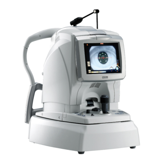
Page 102: Main Body
XSO1**RDA002A 9.1.2 Main body Anterior eye illumination and LEDs for alignment Hand light Objective lens Head rest External fixa- tion target Chinrest Grip Image cap- turing unit Main unit Base unit Power switch Operation panel Joystick Fuse holder... -
Page 103: Operation Panel
XSO1**RDA002A 9.1.3 Operation panel Function indicator Function toggle switch Menu button Anterior eye/fundus observation toggle switch Control knob Optimize button Clear button Pointing stick Start/Stop button Scan length/angle knob Chinrest Up/Down buttons Pilot lamp Release button 9.1.4 Isolation transformer Outlets (n = 6) Pilot lamp NNNNNN XXXX... -
Page 104: Labels
XSO1**RDA002A 9.2 Labels 9.2.1 Transformer box Front view For USA For 100 V regions NNNNNN XXXX For 200 V regions XXXX NNNNNN... - Page 105 XSO1**RDA002A Rear view For 200 V regions For 100 V regions...
-
Page 106: Main Body
XSO1**RDA002A 9.2.2 Main body Side view For USA For outside USA NNNNNN XXXX XXXX NNNNNN... - Page 107 XSO1**RDA002A Top view...
-
Page 108: Motorized Optical Table
XSO1**RDA002A 9.2.3 Motorized optical table Wiring aperture cap Power switch Grease aperture Inlet Fuse holder... -
Page 109: Wiring Diagram
XSO1**RDA002A 9.3 Wiring Diagram... - Page 110 XSO1**RDA002A Transformer box...
-
Page 111: Connector Cable
XSO1**RDA002A 9.4 Connector Cable 10701-EA01 10701-EA02... - Page 112 XSO1**RDA002A 10701-EA04 10701-EA05 10701-EA06...
- Page 113 XSO1**RDA002A 10701-EA07 10701-EA10...
- Page 114 XSO1**RDA002A 10701-EA11...
- Page 115 XSO1**RDA002A 10701-EA13 10701-EA14...
- Page 116 XSO1**RDA002A 10701-EA15 10701-EA16 10701-EA17...
- Page 117 XSO1**RDA002A 10701-EA18 10701-EA19 10701-EA20...
- Page 118 XSO1**RDA002A 10701-EA21 10701-EA24 10701-EA25...
- Page 119 XSO1**RDA002A 10701-EA26 10701-EA28 10701-EA29 10701-EA30...
- Page 120 XSO1**RDA002A 10701-EA31...
- Page 121 XSO1**RDA002A 10701-EA32...
- Page 122 XSO1**RDA002A 10701-EA34 10701-EA35...
- Page 123 XSO1**RDA002A 10701-EA38 10701-EA39...
- Page 124 XSO1**RDA002A 10701-EA42 10701-EA45 10701-EA46 10701-EA47...
- Page 125 XSO1**RDA002A 10701-EA48 10701-EA49 10701-EA53...
- Page 126 XSO1**RDA002A 10701-EA54 10701-EA55 10701-EA56 10701-EA57...
- Page 127 XSO1**RDA002A 10701-EA58 10701-EA59 10701-EA61 10701-EA63...
- Page 128 XSO1**RDA002A 10701-EA65 10701-EA66 10701-EA67...
- Page 129 XSO1**RDA002A 10701-EA68 10701-EA69 10701-EA70...
- Page 130 XSO1**RDA002A 10701-EA71...
-
Page 131: Switch Positions On Boards
XSO1**RDA002A 9.5 Switch Positions on Boards 10701-BA01... - Page 132 XSO1**RDA002A 10701-BA02...
- Page 133 XSO1**RDA002A 10701-BA06 10701-BA20...
-
Page 134: Parameter List
XSO1**RDA002A 9.6 Parameter List SETUP PARAMETER English MACHINE SETTING STARTUP SETTING VERSION INFO MACHINE SETTING Factory Setting item Alternative Remarks setting HIGH BEEP NONE After 5 min SLEEP After 10 min After 15 min HIGH LCD BACKLIGHT HIGH HAND LIGHT RL DISP OD/OS SCAN WIDTH DISP... - Page 135 XSO1**RDA002A BASIC SETTING Factory Setting item Alternative Remarks setting MACULA LINE MACULA CROSS MACULA MAP STARTUP OCT SETTING MACULA MULTI DISC CIRCLE DISC MAP WIDE 40º × 30º STARTUP SLO SETTING ZOOM 20º × 15º NORMAL Cross (small) LARGE Cross (large) STARTUP FIX MODE EXTERNAL RED EXTERNAL GREEN...
- Page 136 XSO1**RDA002A MACULA MAP Factory Setting item Alternative Remarks setting 3 - 9 mm (10 – 30º) 0.3 mm (1º) increments (WIDE) MAP X WIDTH 6 mm (20º) 3 - 9 mm (10 – 30º) 0.3 mm (1º) increments (WIDE) MAP Y WIDTH 6 mm (20º) 3 - 4.5 mm (10 –...
- Page 137 XSO1**RDA002A DISC CIRCLE Factory Setting item Alternative Remarks setting 3 - 9 mm (10 – 30º) 0.3 mm (1º) increments (WIDE) CIRCLE DIAMETER 3.3 mm (11º) 3 - 4.5 mm (10 – 15º) 0.3 mm (1º) increments (ZOOM) CIRCLE DIAMETER 3.3 mm (11º) A-SCAN POINT 1024...
-
Page 138: Error Code List
XSO1**RDA002A 9.7 Error Code List 9.7.1 Main body Contents Main cause Error code EEPROM failure EEPROM data EEPROM data corruption Disconnection of the OCT camera link cable Failure or break of the OCT camera link cable Connection with PC software Disconnection of the trigger cable Failure or break of the trigger cable Line CCD motor failure... - Page 139 XSO1**RDA002A OCT X galvano driver failure OCT X galvano driver OCT X galvano failure OCT X or Y galvano driver failure OCT Y galvano driver OCT X or Y galvano failure OCT X or Y galvano driver failure OCT galvano mirror OCT X or Y galvano failure OCT SLD SLD module failure...
- Page 140 The system information received from the data base software is not correct. 1001 Connection with DB software RS-3000 Capture is not compatible with the version of the data base software. SLO capture board is not installed. 1002 SLO capture board The setting of the DIP SW on the SLO capture board is not correct.
-
Page 141: Layout Drawing
XSO1**RDA002A 9.8 Layout Drawing 9.8.1 ASSYs 9.8.2 Boards... -
Page 142: Electrical Components
XSO1**RDA002A 9.8.3 Electrical components 9.9 Jigs Part No. Part name 10670-M113 IR sensor card TW Grease gun [High pressure lever gun]: PH-100 [TRUSCO NAKAYAMA 35930-M991 CORP.] 9.10 Consumable Part No. Part name 10730-M142 Grease [Sumitec 304: SUMICO LUBRICANT CO., LTD]... -
Page 143: List Of Replacement Parts And Required Adjustments
XSO1**RDA002A 9.11 List of Replacement Parts and Required Adjustments : Required, : Not required, : Check 7.1.1.1 Main body 7.1.1.2 Operation panel ASSY (10701- 1220) 7.1.1.3 LCD ASSY (10701-1300) 7.1.1.4 Chinrest ASSY (10701-1500) 7.1.1.5 External fixation target ASSY (10701-1520) 7.1.1.6 Lens cap ASSY (10701-2400) 7.1.1.7 Joystick ASSY (30601-2600) 7.1.2.1 Main board (10701-BA01) 7.1.2.2 SW board (10701-BA03) -
Page 144: Screw List
XSO1**RDA002A 9.12 Screw List...
Need help?
Do you have a question about the RS-3000 and is the answer not in the manual?
Questions and answers
Free download software of OCT TS3000