
Related Manuals for Meler Micron Gear Series


Summary of Contents for Meler Micron Gear Series
- Page 1 GLUING SOLUTIONS ADHESIVE INSTRUCTIONS MANUAL MELTER MICRON GEAR SERIES MA-5079-ENG 200718...
- Page 2 The specifications and information contained in this manual may be modified without prior notice. This manual is a translation of the original that was written by Focke Meler Gluing Solutions, S. A. in spanish language. If there is any discrepancy between the different versions of this manual, the original written in the spanish language shall prevail.
-
Page 3: Table Of Contents
Hot-melt melter identification Main components Main components Micron gear with two motor-pumps Control card components Pumping control card components Micron gear series range Micron gear range option accessories Automatic feeder option Gas injection option Air dryer system Bypass valve pressure control system... - Page 4 FOCKE MELER GLUING SOLUTIONS TABLE OF CONTENTS Level control system Warning light option Optional equipment 3. INSTALLATION Introduction Installation requirements Free space Electrical Consumption Compressed air Other factors Unpacking Contents Mounting the equipment Electrical power connection Pneumatic connection Hose and applicator connection...
- Page 5 TABLE OF CONTENTS MA-5079-ENG MICRON GEAR ADHESIVE MELTER 4. MELTER OPERATION General information Filling the tank Starting up the melter equipment Melter equipment displays Displaying the temperature for each component Alarm displays Hot-melt level display (optional) Display and adjustment of the working speed Temperature adjustment Programming the applicator parameters Programming process...
- Page 6 FOCKE MELER GLUING SOLUTIONS TABLE OF CONTENTS Modes of operation 4-24 Mode of operation with internal pumping control and internal speed control 4-24 Mode of operation with internal pumping control and external speed control 4-25 Mode of operation with external pumping control and internal speed control...
- Page 7 TABLE OF CONTENTS MA-5079-ENG MICRON GEAR ADHESIVE MELTER Pump maintenance Inspecting for leaks Gear motor maintenance Cleaning the motor fan Checking the lubricant Recommended lubricants Safety Thermostat Air dryer filter maintenance Remove the equipment from its base 6. TROUBLESHOOTING Melter The unit does not turn on (5, 10 and 20 adhesive melters) The unit does not turn on (35 adhesive melter) Equipment shortcircuit malfunction...
- Page 8 FOCKE MELER GLUING SOLUTIONS TABLE OF CONTENTS Check that the machine is working in the correct operating mode All of the previous premises are OK but the unit still does not perform any pumping operations Level sensor The unit does not indicate the absence of adhesive...
- Page 9 TABLE OF CONTENTS MA-5079-ENG MICRON GEAR ADHESIVE MELTER 8. ELECTRICAL DRAWINGS 9. PNEUMATIC DIAGRAM Components list Pneumatic by-pass valve control system (optional) Air drying system (optional) 10. SPARE PARTS LIST 10-1 A. TANK ASSEMBLY 10-4 B. DISTRIBUTOR UNIT 10-5 C. DISTRIBUTOR SIMPLE/ DOUBLE ASSEMBLY 10-6 D.
- Page 10 FOCKE MELER GLUING SOLUTIONS TABLE OF CONTENTS This page is intentionally left blank.
-
Page 11: Safety Guidelines
SAFETY GUIDELINES MA-5079-ENG MICRON GEAR ADHESIVE MELTER 1. SAFETY GUIDELINES General The information contained in this section applies not only to everyday equipment operation, but also to any procedure carried out on it, whether for preventive maintenance or in the case of repairs and the replacement of worn out parts. -
Page 12: Mechanical Components
FOCKE MELER GLUING SOLUTIONS SAFETY GUIDELINES Mechanical components The hot-melt installation, which is installed to this device, requires moving parts that can cause damage. Use the equipment correctly, and do not remove the safety guards while the equipment is in operation; prevent the risk of possible entrapment due to moving mechanical parts. -
Page 13: Thermal Components
Safety Information Sheet of the adhesive. Materials Meler systems are designed for use with hot-melt adhesives. They should not be used with any other type of material, and especially not with solvents, which may cause personal injury or damage to internal system components. -
Page 14: Intended Use
Note: Do not modify the equipment or use components that were not supplied by Meler. For any modification of a component of the equipment or part of the installation, you must firstly consult the After-Sales Service... -
Page 15: Introduction
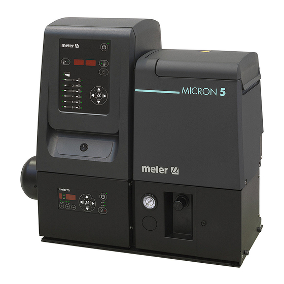
Description These melters are designed for use with Meler hoses and applicators in hot- melt adhesive applications. Their different variations – line, coating or swirl- spray – cover a wide range of applications, being very versatile in all markets... -
Page 16: Modes Of Operation
FOCKE MELER GLUING SOLUTIONS INTRODUCTION Modes of operation These melters may be used in all of the following modes: Work mode_The hot-melt melter keeps materials hot at the pre- selected temperature indicated on the display. The pump is kept activated, waiting for the consumption command when one or more applicators are activated. -
Page 17: Main Components
INTRODUCTION MA-5079-ENG MICRON GEAR ADHESIVE MELTER Main components 1. Front control card. 2. Access door to the electric/pneumatic area. 3. Tank access lid. 4. Main switch ON/OFF. 5. Pumping control card. 6. Air pressure gauge for pneumatic by-pass valve. 7. Pressure regulator of by-pass valve (opcionally pneumatic or mechanical regulator). -
Page 18: Main Components Micron Gear With Two Motor-Pumps
FOCKE MELER GLUING SOLUTIONS INTRODUCTION Main components Micron gear with two motor-pumps Marking of the Micron gear components is the same for all models with two motor-pumps. In this case the pictures refers to the 20-liter model. For each motor-pump assembly installed: 1. -
Page 19: Control Card Components
INTRODUCTION MA-5079-ENG MICRON GEAR ADHESIVE MELTER Control card components 1. Tank indicator LED. 2. Applicator indicator LED. 3. Temperature set point. 4. Real temperature. 5. ON/OFF switch. 6. Standby function. 7. Temperature OK LED. 8. Time scheduling. 9. Left/right button - channel selection. 10. -
Page 20: Pumping Control Card Components
FOCKE MELER GLUING SOLUTIONS INTRODUCTION Pumping control card components 1. Main switch ON/OFF. 2. External start-stop LED. 3. External speed control LED. 4. Pumping permission LED. 5. Up/down arrow keys for selecting values. 6. Left/right arrow keys for selecting options. -
Page 21: Micron Gear Series Range
INTRODUCTION MA-5079-ENG MICRON GEAR ADHESIVE MELTER Micron gear series range Micron low level warning light - B0: no warning light / B1: with warning light low level detector - LD0: no detector LD1: floating-type det. / LD2: capacitive det. bypass valve pressure control system - PC: pneumatic reg. -
Page 22: Gas Injection Option
FOCKE MELER GLUING SOLUTIONS INTRODUCTION Gas injection option There is the possibility of preparing the equipment with an air or gas input into the reservoir. This entrance is done from the top and the equipment is prepared from the factory. -
Page 23: Installation
• Optionally, a gas ventilation system. Installation requirements Before installing Micron gear series melter equipment, we must make sure that the space assigned to it permits installing, connecting and using the entire system. Similarly, we must check to see that the electrical and pneumatic supplies meet the necessary requirements of the melter equipment being installed. -
Page 24: Electrical Consumption
FOCKE MELER GLUING SOLUTIONS INSTALLATION To calculate the space necessary to install the equipment in terms of its length, you must add at least 280 mm to the measurements indicated in the table in order to be able to open the distributor’s filter-purger access door. -
Page 25: Compressed Air
Communicate any defect, even to the outer packing materials, to your Meler Representative or to the Main Office. Contents The equipment packing materials may contain accessories that form part of the same order. -
Page 26: Mounting The Equipment
Slide the unit to its final position. Lock the wheels once again, lowering the levers. Electrical power connection Micron gear series melters are designed to be connected to the electrical power supply in two possible ways, depending on the power of different elements connected: •... -
Page 27: Pneumatic Connection
INSTALLATION MA-5079-ENG MICRON GEAR ADHESIVE MELTER L3 N PE L1 L2 L3 N PE LN~230V 50/60Hz + PE 3N~400V 50/60Hz + PE WITHOUT NEUTRAL L1 L2 L3 PE 3~230V 50/60Hz + PE Warning: Risk of electrical shock. Carelessness may cause injury or death. Open the electric cabinet door as far as possible. -
Page 28: Hose And Applicator Connection
Once the melter and its components are installed, you will need to program the operational parameters appropriate for the specific application that will be performed. Micron gear series simplify this task as much as possible, allowing the operator to modify only those parameters that are necessarily variable for each application. -
Page 29: Programming Working Temperatures
INSTALLATION MA-5079-ENG MICRON GEAR ADHESIVE MELTER in advanced systems, although the factory default values are perfectly valid for operational purposes. Programming working temperatures The melters leave the factory with the following set point temperatures: • 160 °C for the tank and the distributor. •... -
Page 30: Keeping A Component On Display
FOCKE MELER GLUING SOLUTIONS INSTALLATION 4. Use the right arrow to advance to the next screen. 5. Exit the special menu using the left arrow and the tank temperatures will once again be displayed. All the special menu values will be saved. -
Page 31: Temperature Ok
INSTALLATION MA-5079-ENG MICRON GEAR ADHESIVE MELTER • Output disabled_disabled input signal for each hose-applicator output via a non-voltage contact. With a closed contact, the output remains activated (output on); with an open contact, it is deactivated (output off). • Motor start up_for each pump installed, the motor start up may be controlled by closing an external non-voltage contact. -
Page 32: External Standby
FOCKE MELER GLUING SOLUTIONS INSTALLATION 3. Connect the two wires from the start-up signal to the terminals Tok1 and Tok2. This is a double terminal, which makes it necessary to connect each wire in one of the two holes in the terminal. Since this contact is not under voltage, there is no connection polarity. -
Page 33: Output Disabled
INSTALLATION MA-5079-ENG MICRON GEAR ADHESIVE MELTER 2. Thread the power cord (max. Ø12.5mm) through the electrical wall bushing Pg13.5 and fasten it to the inside anchor, making sure that the cord reaches the power card connector at the position where it will be installed (CN 1). -
Page 34: Starting Up The Motor (Ok Ext)
FOCKE MELER GLUING SOLUTIONS INSTALLATION 4. Reconnect the card connector. 5. Make sure that the cable is well connected and that its path through the electrical cabinet presents no risks of snagging, being cut or any other accidental deterioration. It is possible to select the channels that you want to control from the outside using the small switches located above the connecter. -
Page 35: Failures Output In Pump Control Card
INSTALLATION MA-5079-ENG MICRON GEAR ADHESIVE MELTER 3. Connect the two wires from the start-up signal to the terminals XV1 and XV2. This is a double terminal, which makes it necessary to connect each wire in one of the two holes in the terminal. The positive signal wire must be connected to point XV2 of the terminal, while the negative wire must be connected to point XV1. - Page 36 FOCKE MELER GLUING SOLUTIONS INSTALLATION This page is intentionally left blank. 3-14...
-
Page 37: Melter Operation
MELTER OPERATION MA-5079-ENG MICRON GEAR ADHESIVE MELTER 4. MELTER OPERATION In this section we will introduce the method for using the melter. Although its operation is very simple, it should not be used by untrained personnel. Warning: Improper use may cause damage to the machine or injury and even death to the person using it. -
Page 38: Filling The Tank
FOCKE MELER GLUING SOLUTIONS MELTER OPERATION Filling the tank The tank may be equipped optionally with two types of detectors: capacitive or float detectors. The capacitive detector issues a warning when the adhesive reaches the programmed level, thanks to a low adhesive level signal. A float type detector issues a warning when the molten hot-melt drops to one third of its capacity. -
Page 39: Melter Equipment Displays
MELTER OPERATION MA-5079-ENG MICRON GEAR ADHESIVE MELTER If the control card was on the last time that the machine was disconnected, it will turn on when the machine is started up again. 2. Press the ON/OFF button on the control card to turn it on, if it not already activated. -
Page 40: Displaying The Temperature For Each Component
FOCKE MELER GLUING SOLUTIONS MELTER OPERATION LED display On/off Standby constantly lit turned off unit function activated deactivation programmed for the activation programmed for the blinking slowly current day current day activation/deactivation activation/deactivation blinking rapidly programming mode programming mode unit in operation... -
Page 41: Alarm Displays
MELTER OPERATION MA-5079-ENG MICRON GEAR ADHESIVE MELTER Alarm displays The melter equipments tell the user when a malfunction has occurred in the unit, sending warning messages that may be seen on the control panel display. When an alarm appears, the control unit takes a series of steps to protect the unit. - Page 42 FOCKE MELER GLUING SOLUTIONS MELTER OPERATION Actions Code Source Heating Pump Main machine signal tank broken sensor only tank off distributor1 broken sensor only distributor1 off null distributor2 broken sensor only distributor2 off null hose1 broken sensor only hose1 off...
-
Page 43: Hot-Melt Level Display (Optional)
MELTER OPERATION MA-5079-ENG MICRON GEAR ADHESIVE MELTER Standby function does not generate any alarm. If a temperature sensor is broken, the system heats all the elements except the one where the failure is located. In case of overheating the system cuts off inmediately the damaged element. After three minutes if the failure continues all the system will be shut down. -
Page 44: Temperature Adjustment
FOCKE MELER GLUING SOLUTIONS MELTER OPERATION Temperature adjustment The melters leave the factory with the following set point temperature values: • 160 °C for the tank and distributor • 160 ºC for the hoses and applicators • °C displayed • Overheating value: 20°C •... -
Page 45: Programming The Applicator Parameters
MELTER OPERATION MA-5079-ENG MICRON GEAR ADHESIVE MELTER Programming the applicator parameters The access to the parameters is performed from the special menu. Simulta- neously press the buttons with the clock symbol and the down arrow to enter this menu. The navigation order is as follows: Symbol on the dis- Function Default value... - Page 46 FOCKE MELER GLUING SOLUTIONS MELTER OPERATION 3. Use the right arrow to move to the next display where the overheating symbol appears. 4. Select the desired value (between 10 and 25) using the up-down arrow. The value shown corresponds to the increase in real temperature allowed over the set point temperature without activating the alarm message.
- Page 47 MELTER OPERATION MA-5079-ENG MICRON GEAR ADHESIVE MELTER 12. Use the up-down arrow to select the desired value (see ‘Timer to switch between ON - Standby - OFF modes’). 13. Use the right arrow to go to the next display. 14. Use the up-down arrow to select the desired value (see ‘Timer to switch between ON - Standby - OFF modes’).
- Page 48 FOCKE MELER GLUING SOLUTIONS MELTER OPERATION 18. Use the right arrow to go to the next display. 19. Use the up-down arrow to select the desired value (see ‘Counter that warns of the need to change the adhesive agent filter’).
-
Page 49: Timer To Switch Between On - Standby - Off Modes
MELTER OPERATION MA-5079-ENG MICRON GEAR ADHESIVE MELTER Timer to switch between ON - Standby - OFF modes This function is used to program automatic switching from the ON mode to Standby mode after an inactive period of time (S-1) and from STANDBY mode to OFF mode after another waiting period (S-2) during which activity has not been resumed. -
Page 50: Password To Access Parameter Programming
FOCKE MELER GLUING SOLUTIONS MELTER OPERATION Password to access parameter programming A Password can be programmed to protect access to certain equipment pro- gramming functions by unauthorised users. The special menu can be used to program a value between 000 (disabled) and 999. -
Page 51: Counter That Warns Of The Need To Change The Adhesive Agent Filter
MELTER OPERATION MA-5079-ENG MICRON GEAR ADHESIVE MELTER Counter that warns of the need to change the adhesive agent filter This function is a partial countdown counter that registers the hours of equi- pment operation, that is, with service temperature OK activated, from tP1000 hours to tP0000 hours. -
Page 52: Setting The Clock
FOCKE MELER GLUING SOLUTIONS MELTER OPERATION Setting the clock ‘micron’ series melters are equipped with a weekly programmable system controlling equipment connection and disconnection and activating and deac- tivating the standby function. Before programming these functions, it is necessary to introduce into the control unit data corresponding to the day and hour used to execute these programs. -
Page 53: Programming Equipment Activation/Deactivation
MELTER OPERATION MA-5079-ENG MICRON GEAR ADHESIVE MELTER Programming equipment activation/deactivation You may program an activation and a deactivation time for every day of the week, from Monday (1) to Sunday (7). Time is expressed in 15 minute increments, so we cycle from 10.0 (10 hours and 0 minutes) to 10.1 (10 hours and 15 minutes) to 10.2 (10 hours and 30 minutes) to 10.3 (10 hours and 45 minutes). -
Page 54: Disabling The Equipment Activation/Deactivation Program
FOCKE MELER GLUING SOLUTIONS MELTER OPERATION Disabling the equipment activation/deactivation program It is possible to disable the equipment activation/deactivation programming without canceling the daily programming. This way the programmed data is saved, but the programming will have no effect on the equipment. -
Page 55: Disabling The Equipment Standby Function Programming
MELTER OPERATION MA-5079-ENG MICRON GEAR ADHESIVE MELTER Two times will appear, one in each display. The left display shows the start time, while the right display shows the finish time. 5. The blinking dot next to the start time indicates that this is the time that may be modified. -
Page 56: Special Function Buttons
FOCKE MELER GLUING SOLUTIONS MELTER OPERATION 4. Press the button with the clock symbol once again. The status will alternate each time you press the button. 5. Pressing either the left or the right arrow button will exit this program and return to the tank temperature display. -
Page 57: Pumping Control
MELTER OPERATION MA-5079-ENG MICRON GEAR ADHESIVE MELTER Pumping control Starting up the pump control card The pump control card (hereingafter also control card), features an ON-OFF button that allows us to turn off the displays and LEDs (leaving on only the 24 Vdc power supply LED) The control card will turn off automatically depending on the status of pumping permission input:... -
Page 58: Password Security
FOCKE MELER GLUING SOLUTIONS MELTER OPERATION • Whenever an error occurs, the control disables pumping (red ON-OFF button LED is illuminated) and prevents the operation of the pump until the error is reset, the pumping ON-OFF button is pressed again and the red LED turns off. -
Page 59: Led Indicators
MELTER OPERATION MA-5079-ENG MICRON GEAR ADHESIVE MELTER LED indicators Described below are the LED indicators on the pump control card to identify the status of the equipment: 1. Control card ON/OFF LED: when the external 24 Vdc power supply is present, this LED will always be illuminated;... -
Page 60: Modes Of Operation
FOCKE MELER GLUING SOLUTIONS MELTER OPERATION Modes of operation First of all, we must bear in mind that when password security is enabled and the control card is not manipulated during one minute, it is blocked and you need to enter the password. To prevent this from happening, password security may be disabled following the steps in the section ‘Password security’. -
Page 61: Mode Of Operation With Internal Pumping Control And External Speed Control
MELTER OPERATION MA-5079-ENG MICRON GEAR ADHESIVE MELTER Mode of operation with internal pumping control and external speed control In this operating mode, pumping is controlled from the equipment and speed is controlled by a 0-10 V external signal from the main machine. Follow the steps below to use this operating mode: 1. -
Page 62: Mode Of Operation With External Pumping Control And Internal Speed Control
FOCKE MELER GLUING SOLUTIONS MELTER OPERATION Mode of operation with external pumping control and internal speed control In this operating mode, pumping is controlled from the main machine while speed is controlled from the equipment. Follow the steps below to use this operating mode: 1. -
Page 63: Mode Of Operation With External Pumping Control And External Speed Control
MELTER OPERATION MA-5079-ENG MICRON GEAR ADHESIVE MELTER Mode of operation with external pumping control and external speed control In this working mode, both pumping and speed are controlled from the main machine. Follow the steps below to use this operating mode: 1. -
Page 64: User Configuration Menu
‘User configuration menu’, ‘1. MAXIMUM RPM’. The pump control card is designed with certain parameters programmed at Meler that can be modified if necessary to meet your requirements. Modifications may be made through the user configuration and programming speed ramp menus. -
Page 65: Displaying Alarms And Reset Function
MELTER OPERATION MA-5079-ENG MICRON GEAR ADHESIVE MELTER Displaying alarms and reset function Maximum rpm alarm This alarm will be triggered when the motor rotates at a speed exceeding the MAXIMUM RPM ALARM value for the period established in the MAXIMUM RPM ALARM TIME field. -
Page 66: Configuring Speed Ramp
FOCKE MELER GLUING SOLUTIONS MELTER OPERATION Configuring speed ramp For equipment operating in external reference, the display will show the current pump rotation set point (input reference conversion as per the full scale and the conversion table). The conversion table may be programmed with up to 5 points (input voltage (V) and output speed (RPM)). -
Page 67: Programming Speed Ramp
MELTER OPERATION MA-5079-ENG MICRON GEAR ADHESIVE MELTER Programming speed ramp To access this menu and program the different points corresponding to the voltage- speed ratio, you must select external reference (‘ref ext’ LED is illuminated) and press the right arrow key. Then the following message is displayed: The IN LED to the position ON and the OUT LED to the position OFF, 1 000, NOT EDITABLE;... -
Page 68: Current Vin Voltage Display
FOCKE MELER GLUING SOLUTIONS MELTER OPERATION Current Vin voltage display Whenever the Vin key is held pressed, the three digits on the right will show the input voltage reading to one decimal point. If the values for any point in the speed ramp table is being edited, and the Vin key is held pressed for 3 seconds, the voltage value which is operating at this time it will be copied to that value on the table. -
Page 69: Using The Air Drying System (Optional)
MELTER OPERATION MA-5079-ENG MICRON GEAR ADHESIVE MELTER Warning: Do not exceed 6 bar of pressure. This corresponds to 80 bar on the hydraulic circuit. Using the air drying system (optional) regulators inlet solenoid valve Polyurethane-based reactive adhesives require a completely dry environment before they can be applied, since when they come in contact with atmospheric humidity, they reticulate, hardening quickly. - Page 70 FOCKE MELER GLUING SOLUTIONS MELTER OPERATION This page is intentionally left blank. 4-34...
-
Page 71: Maintenance
MAINTENANCE MA-5079-ENG MICRON GEAR ADHESIVE MELTER 5. MAINTENANCE Warning: The melter equipment is equipped with current technology, but has certain foreseeable risks. Therefore, only allow qualified personnel with enough training and experience to operate install or repair this equipment. The following table briefly summarizes the indications for adequate melter/ equipment maintenance. - Page 72 FOCKE MELER GLUING SOLUTIONS MAINTENANCE To carry out external cleaning: • Use cleaning products compatible with polyamide materials. • Apply the cleaning product with a soft cloth. • Do not use sharp tools or scrapers with sharp edges. Removing and changing exterior panels: 1.
-
Page 73: System Depressurisation
MAINTENANCE MA-5079-ENG MICRON GEAR ADHESIVE MELTER System depressurisation Even with the motor turned off, residual pressure may exist in the circuit. This must be kept in mind when performing any operation on the hydraulic circuit. Before disconnecting any hydraulic element or opening any distributor outlet, it is necessary to perform the following steps: 1. -
Page 74: Filter Maintenance
FOCKE MELER GLUING SOLUTIONS MAINTENANCE Filter maintenance Micron gear series melter equipment is equipped with a 50 mesh pump filter. The filter prevents impurities and burnt adhesive remains from being pushed out from the tank by the pump. Warning: It is a good idea to also use a grill in the tank. This grill performs a first-step filtration, preventing great impurities. -
Page 75: Cleaning The Tank
MAINTENANCE MA-5079-ENG MICRON GEAR ADHESIVE MELTER 7. Replace the assembly inside the distributor and fasten it clockwise. Tighten the purge screw clockwise with a flat blade screwdriver. 8. Continue working as usual. Cleaning the tank The hot-melt tank must be cleaned on occasion to maintain its fusion and anti-adherence properties. -
Page 76: Emptying The Tank
FOCKE MELER GLUING SOLUTIONS MAINTENANCE 4. Remove the filter cartridge and clean it, if necessary (see the section ‘Filter maintenance’). 5. Reassemble the filter without the cartridge. 6. Pump a minimum of one tank through any distributor output. 7. Remove the filter and attach it to the corresponding cartridge. Reinstall it in the distributor. -
Page 77: Pump Maintenance
Before making any changes, establish the location of the leak. However, before replacing any parts and in case of any doubt, we recommend that you consult the Meler Technical Service Centre. Warning: Always wear protective gloves and goggles. Risk of burns. -
Page 78: Recommended Lubricants
FOCKE MELER GLUING SOLUTIONS MAINTENANCE Recommended lubricants BRAND TYPE OF OIL Telesia Compound A SHELL Tivela Compound A MOBIL Glygoyle Grease 00 Safety Thermostat If there is a deactivation of the thermostat, dismantle the tank casing with the cover and slide the electrical cabinet along. When you can see the thermostat, press the button indicated to reset it. -
Page 79: Remove The Equipment From Its Base
MAINTENANCE MA-5079-ENG MICRON GEAR ADHESIVE MELTER Remove the equipment from its base For more thorough equipment maintenance, it is necessary to remove it from its present location to be able to perform operations more comfortably and with greater accessibility. To do this, the equipment should be removed from its base following these indications: 1. - Page 80 FOCKE MELER GLUING SOLUTIONS MAINTENANCE This page is intentionally left blank. 5-10...
-
Page 81: Troubleshooting
If you do not reach the cause follow to the next problem. If you are unable to solve the problem with the help provided in this chapter, contact your Area Technical Service Center or Meler headquarter directly. -
Page 82: Melter
FOCKE MELER GLUING SOLUTIONS TROUBLESHOOTING Melter The unit does not turn on (5, 10 and 20 adhesive melters) Causes Checking Comments Actions Check voltage between phases Check wiring. Equipment power and neutrals in the main terminal. Voltages will vary depending on Check net power supply malfunction. -
Page 83: Equipment Shortcircuit Malfunction
TROUBLESHOOTING MA-5079-ENG MICRON GEAR ADHESIVE MELTER Equipment shortcircuit malfunction Causes Checking Comments Actions If the tank is shortcircuited, the Check wiring, some Disconnect CN6 connector system will turn on. Reconnect CN6 Shortcircuit in tank. cables might be bypassed. from the power board. and release the wires from the tank Change tank. -
Page 84: The Tank Does Not Stop Heating (5, 10 And 20 Adhesive Melters)
FOCKE MELER GLUING SOLUTIONS TROUBLESHOOTING Causes Checking Comments Actions Check for continuity in If there is continuity between the Faulty power contacts the power contacts of the contacts of the contactor and it receives Replace the contactor. in the contactor. -
Page 85: Manifold
TROUBLESHOOTING MA-5079-ENG MICRON GEAR ADHESIVE MELTER Manifold The manifold does not heat (Micron, 1 geared motor) Causes Checking Comments Actions Check voltage between Check wiring. Check net Equipment power phases and neutrals. Voltages will vary depending on power supply. Change supply malfunction. -
Page 86: The Manifold Does Not Stop Heating (Micron, 2 Geared Motores)
FOCKE MELER GLUING SOLUTIONS TROUBLESHOOTING The manifold does not stop heating (Micron, 2 geared motores) Causes Checking Comments Actions Power board Check the power board. LED indicator DL(*) remains off. Change power board. (4 ) malfunction. Control board Check the control board. -
Page 87: Check That The Machine Is Working In The Correct Operating Mode
E.U Error on the board Check possible causes of the error Contact Meler's Service Variator alarm. display. in the Siemens variator. Centre. Check that the machine is working in the correct operating mode... -
Page 88: Level Sensor
The lack of adhesive If you do not know how to open Check the parameter in Change the parameter in warning is not this menu, contact Meler's Service the setup menu. the menu. activated in the board Centre. Check for continuity in pins... -
Page 89: Hose
TROUBLESHOOTING MA-5079-ENG MICRON GEAR ADHESIVE MELTER Hose Hose does not heat Causes Checking Comments Actions Replace the hose by Hose damaged. Change hose channel. Change hose. another one that works. Check voltage between Pins and wiring board and hose-output CN(*) connector (black wire-neutral Change connectors. -
Page 90: Applicator
FOCKE MELER GLUING SOLUTIONS TROUBLESHOOTING Micron with 2 geared motor Note Hose 1 Hose 2 Hose 3 Hose 4 CN10 / M3 CN10 / M4 CN11 / M5 CN11 / M6 CN10 / M3 / DL7 CN10 / M4 / DL9... - Page 91 TROUBLESHOOTING MA-5079-ENG MICRON GEAR ADHESIVE MELTER Micron 1 geared motor Note Applicator 1 Applicator 2 Applicator 3 Applicator 4 Applicator 5 Applicator 6 CN9 / P1 CN9 / P2 CN10 / P3 CN10 / P4 CN11 / P5 CN11 / P6 CN9 / P1 / DL4 CN9 / P2 / DL6 CN10 / P3 / DL8...
-
Page 92: Lay Out Power Board
FOCKE MELER GLUING SOLUTIONS TROUBLESHOOTING LAY OUT POWER BOARD CN10 DL10 CN11 DL11 DL12 DL14 DL13 CN9,CN10 and CN11 Channel 2, 4 or 6 Channel 1, 3 or 5 Applicator Tank Common Hose Distributor 6-12... -
Page 93: Lay Out Control Board
TROUBLESHOOTING MA-5079-ENG MICRON GEAR ADHESIVE MELTER LAY OUT CONTROL BOARD LAY OUT SENSOR BOARD CN11 Distributor Tank CN2, CN3, CN4, CN5, CN6,CN7 Applicator Hose LAY OUT PUMP CONTROL BOARD S6 S5 E3 E4 6-13... - Page 94 FOCKE MELER GLUING SOLUTIONS TROUBLESHOOTING This page is intentionally left blank. 6-14...
-
Page 95: Technical Characteristics
TECHNICAL CHARACTERISTICS MA-5079-ENG MICRON GEAR ADHESIVE MELTER 7. TECHNICAL CHARACTERISTICS Generals Tank capacity 5,15 liters 9,7 liters Pumping rate simple pump 1, 2.5, 4, 8 cc/rev (*) 1, 2.5, 4, 8 cc/rev (*) double pump (per output 2x0.93, 2x1.86, 2x3.71, 2x4.8 cc/rev (*) 2x0.93, 2x1.86, 2x3.71, 2x4.8 cc/rev (*) Melting rate 9,0 kg/h (*) - Page 96 FOCKE MELER GLUING SOLUTIONS TECHNICAL CHARACTERISTICS Tank capacity 19,7 liters 37,4 liters Pumping rate simple pump 1, 2.5, 4, 8 cc/rev (*) 1, 2.5, 4, 8 cc/rev (*) double pump (per output 2x0.93, 2x1.86, 2x3.71, 2x4.8 cc/rev (*) 2x0.93, 2x1.86, 2x3.71, 2x4.8 cc/rev (*)
-
Page 97: Dimensions
TECHNICAL CHARACTERISTICS MA-5079-ENG MICRON GEAR ADHESIVE MELTER Dimensions Micron 5, 10 670+250 (Micron 10) 730 (Micron 10) 670 (Micron 10) Micron 10 590 (Micron 5) 730 (Micron 5) 590+250 (Micron 5) Micron 20, 35 740+250 (Micron 35) 740 (Micron 35) Micron 35 Micron 35 Formación requerida... - Page 98 FOCKE MELER GLUING SOLUTIONS TECHNICAL CHARACTERISTICS MOUNTING THE EQUIPMENT Micron 5 377,5 MOUNTING THE EQUIPMENT Micron 10 569,5 Ø9 Formación requerida EQUIPO ZAPATOS GUANTES GAFAS OTROS ón Calidad Producción Piezas en proceso MANTENER ORDEN Y LIMPIEZA operario EN EL PUESTO Y...
-
Page 99: Micron Gear Range Option Accessories
Micron gear range option accessories Automatic feeder system Meler adhesive loaders ensure a continuous level of adhesive inside the tanks of the melting units, eliminating the need for manual loading by the user. Each time the tank sensor detects a low level of adhesive, it sends a signal to the suction system, which transfers a load of pellets to the melting tank from the adhesive container (or directly from the bag it comes in). -
Page 100: Optional Equipment
FOCKE MELER GLUING SOLUTIONS TECHNICAL CHARACTERISTICS Optional equipment Wheel system For all the Micron gear machines there is the option to add 4 wheels to the base of the machine to make it easier to move. -
Page 101: Electrical Drawings
ELECTRICAL DRAWINGS MA-5079-ENG MICRON GEAR ADHESIVE MELTER 8. ELECTRICAL DRAWINGS To view the the electrical drawing of the purchased equipment, see the CD of electrical drawings included. - Page 102 FOCKE MELER GLUING SOLUTIONS ELECTRICAL DRAWINGS This page is intentionally left blank.
-
Page 103: Pneumatic Diagram
PNEUMATIC DIAGRAM MA-5079-ENG MICRON GEAR ADHESIVE MELTER 9. PNEUMATIC DIAGRAM Components list Pneumatic by-pass valve control system (optional) Pressure regulator 1-10 bar Pressure gauge 0-10 bar Pneumatic limit control valve REGULADOR DE PRESIÓN MANÓMETRO PRESSURE REGULATOR MANOMETER P: 0-10 bar P: 0-10 bar VÁLVULA LIMITADORA / PRESSURE LIMIT VALVE RELACIÓN / RATIO 1:15... -
Page 104: Air Drying System (Optional)
FOCKE MELER GLUING SOLUTIONS PNEUMATIC DIAGRAM Air drying system (optional) Filter– 1st stage, grade 7 Filter – 2nd stage, grade 5 Air dryer 3/2 solenoid valve with manual control Pressure regulator 1-10 bar Pneumatic relief valve 0.5 bar Pressure regulator 0.1-0.7 bar Pressure gauge 0-1.6 bar... -
Page 105: 10. Spare Parts List
MICRON GEAR ADHESIVE MELTER 10. SPARE PARTS LIST The list of the most common spare parts for Micron gear series machines appears in this section, providing a quick and reliable guide to choosing them. The spare parts are grouped together naturally, in the same way as they are located in the melters. - Page 106 FOCKE MELER GLUING SOLUTIONS SPARE PARTS LIST This page is intentionally left blank. 10-2...
- Page 107 SPARE PARTS LIST MA-5079-ENG MICRON GEAR ADHESIVE MELTER CHASSIS ASSEMBLY GAS INJECTION ASSEMBLY TANK ASSEMBLY AIR DRYER ASSEMBLY TANK- DISTRIBUTOR DISTRIBUTOR UNION ASSEMBLY ASSEMBLY PNEUMATIC COMPONENTS GEARED MOTOR- PUMP ASSEMBLY ELECTRIC ASSEMBLY ELECTRONIC ASSEMBLY EQUIPO ZAPATOS GUANTES GAFAS OTROS Producción Calidad MANTENER ORDEN Y LIMPIEZA EN EL PUESTO Y...
-
Page 108: Tank Assembly
FOCKE MELER GLUING SOLUTIONS SPARE PARTS LIST A. TANK ASSEMBLY Nº Ref. Description 150113470 Complete tank assembly micron 5 230V 150113480 Complete tank assembly micron 10 230V 150113490 Complete tank assembly micron 20 230V 150114890 Complete tank assembly micron 35 230V... -
Page 109: Distributor Unit
SPARE PARTS LIST MA-5079-ENG MICRON GEAR ADHESIVE MELTER B. DISTRIBUTOR UNIT Nº Ref. Description 150113570 Tank-distributor union o-rings. Micron 5, 10, 20 150026380 Coupling tank-distributor o-rings. Micron 5, 10, 20 150090360 Tank-distributor union o-rings. Micron 35 150023950 Coupling tank-distributor o-rings. Micron 35 10-5... -
Page 110: Distributor Simple/ Double Assembly
FOCKE MELER GLUING SOLUTIONS SPARE PARTS LIST C. DISTRIBUTOR SIMPLE/ DOUBLE ASSEMBLY Nº Ref. Description 150026270 Pneumatic pressure regulator 150026300 Pneumatic pressure regulator o-rings 150121390 Filter assembly 150121380 Filter head with purger 150029250 Filter mesh 150029260 O-ring Ø23X3 150026340 O-ring 7 x 1.5... -
Page 111: Geared Motor-Pump Assembly
SPARE PARTS LIST MA-5079-ENG MICRON GEAR ADHESIVE MELTER D. GEARED MOTOR-PUMP ASSEMBLY Nº Ref. Description 150117170 Geared motor 0.375 KW with booster fun 150117150 Simple pump motor coumpling 150117160 Double pump motor coumpling 150026430 Simple pump o-rings 150111890 Double pump o-rings 150025960 Simple gear pump 1 cc/rev 150114020... -
Page 112: Chassis Assembly
FOCKE MELER GLUING SOLUTIONS SPARE PARTS LIST E. CHASSIS ASSEMBLY Nº Ref. Description 1 (*) 150117140 Micron electrical cabinet door casing 150113290 Electrical cabinet casing assembly without warning light 150113360 Electrical cabinet casing assembly with warning light 150113300 Micron 5 tank housing assembly... -
Page 113: Electric Assembly
SPARE PARTS LIST MA-5079-ENG MICRON GEAR ADHESIVE MELTER F. ELECTRIC ASSEMBLY Nº Ref. Description 10010300 Fuse 6,3A 5x20 150028860 Fuse 6,3A 6x32 150021540 Fuse 16A 10x38 150114450 Control to power board ribbon cable assembly 150024740 Control to sensor board cable assembly 16010003 Female connector 8 pin (base housing) 150020720... -
Page 114: Electronic Assembly
FOCKE MELER GLUING SOLUTIONS SPARE PARTS LIST G. ELECTRONIC ASSEMBLY Nº Ref. Description 150113660 Control board Micron 150113670 Power board Micron 2 outlets 150113680 Power board Micron 6 outlets 150024710 Sensor board Micron Pt100/Ni120 150110970 Fuse 0,315A 5x20 150117100 Pump control board... -
Page 115: Pneumatic Components
SPARE PARTS LIST MA-5079-ENG MICRON GEAR ADHESIVE MELTER H. PNEUMATIC COMPONENTS Nº Ref. Description 150110730 Pneumatic limit valve 150114480 Pressure gauge 10110031 Pressure regulator Note: these elements are added to the equipment when by-pass pneumatic regulation. I. GAS INJECTION ASSEMBLY (OPTIONAL) Nº... -
Page 116: Air Dryer Assembly (Optional)
FOCKE MELER GLUING SOLUTIONS SPARE PARTS LIST J. AIR DRYER ASSEMBLY (OPTIONAL) Nº Ref. Description 150110410 Air dryer excelon pro 92 series 150110390 Filter F92C-NND-AT0 150110400 Filter F92G-NNN-AT1 10110031 Pressure regulator 150029540 Pressure regulator 0,1-0,7 bar 150029550 Pressure gauge 0-1,6 bar 150028380 Pneumatic limit vale 0.5 bar 1/4’... -
Page 117: Ec Declaration Of Conformity
EC DECLARATION OF CONFORMITY Original Declaration The manufacturer, Focke Meler Gluing Solutions, S.A. Pol. Los Agustinos, c/G, nave D-43 E-31160 Orkoien, Navarra - Spain — A Focke Group Company — declaring that the machinery, Type: Model: Serial Number: fulfils all the relevant provisions of the Directive 2006/42/EC on machinery,... - Page 118 For more information speak with your Focke Meler representative: Focke Meler Gluing Solutions, S. A. Pol. Los Agustinos, c/G, nave D-43 E-31160 Orkoien - Navarra - Spain Phone: +34 948 351 110 Fax: +34 948 351 130 info@meler.eu - www.meler.eu...
Need help?
Do you have a question about the Micron Gear Series and is the answer not in the manual?
Questions and answers