
Related Manuals for Meler MACRO FOAM Series


Summary of Contents for Meler MACRO FOAM Series
- Page 1 GLUING SOLUTIONS ADHESIVE INSTRUCTIONS MANUAL MELTER MACRO FOAM SERIES MA-5127-ENG 231220...
- Page 2 Published by: Focke Meler Gluing Solutions, S.A. Pol. Arazuri-Orkoien, c/B, nº3 A E-31170 Arazuri - Navarra - Spain Phone: +34 948 351 110 info@meler.eu - www.meler.eu Focke Group Edition December 2020 © Copyright by Focke Meler All rights reserved. Its reproduction, diffusion or use by electronic or other means of all or any part of this document without the express authorization of its owner is strictly prohibited.
-
Page 3: Table Of Contents
TABLE OF CONTENTS MA-5127-ENG MACRO FOAM SERIES MELTER MANUAL TABLE OF CONTENTS 1. SAFETY GUIDELINES General Symbols Mechanical components Electrical components Hydraulic components Pneumatic components Thermal components Materials Noise emission declaration Intended use Limited use 2. INTRODUCTION Description Intended use... - Page 4 FOCKE MELER GLUING SOLUTIONS TABLE OF CONTENTS 3. INSTALLATION Introduction Installation requirements Free space Electrical Consumption Compressed air Other factors Unpacking Contents Mounting the equipment Electrical power connection Pneumatic connection Hose and applicator connection Parameter Programming Programming working temperatures Selecting the overheating value...
- Page 5 TABLE OF CONTENTS MA-5127-ENG MACRO FOAM SERIES MELTER MANUAL 4. MELTER OPERATION General information Filling the tank Starting up the melter equipment Melter equipment displays Displaying the temperature for each component Alarm displays Hot-melt display level (optional) Display and adjustment of the working pressure...
- Page 6 FOCKE MELER GLUING SOLUTIONS TABLE OF CONTENTS Displaying alarms and reset function 4-23 Maximum pressure alarm 4-23 Minimum pressure alarm 4-23 Variator alarm 4-23 Configuring pressure curve 4-23 Programming pressure curve 4-25 Current Vin voltage display 4-26 By-pass valve regulation...
- Page 7 TABLE OF CONTENTS MA-5127-ENG MACRO FOAM SERIES MELTER MANUAL Pump maintenance Inspecting for leaks Changing the pump probe Gas injection valve cleaning Motor-gear maintenance Cleaning the motor fan Checking the lubricant Recommended lubricants Thermostats maintenance 6. TECHNICAL CHARACTERISTICS General Dimensions 7.
- Page 8 FOCKE MELER GLUING SOLUTIONS TABLE OF CONTENTS This page is intentionally left blank.
-
Page 9: Safety Guidelines
SAFETY GUIDELINES MA-5127-ENG MACRO FOAM SERIES MELTER MANUAL 1. SAFETY GUIDELINES General The information contained in this section applies not only to everyday equipment operation, but also to any procedure carried out on it, whether for preventive maintenance or in the case of repairs and the replacement of worn out parts. -
Page 10: Mechanical Components
FOCKE MELER GLUING SOLUTIONS SAFETY GUIDELINES Mechanical components The hot-melt installation, which is installed to this device, requires moving parts that can cause damage. Use the equipment correctly, and do not remove the safety guards while the equipment is in operation; prevent the risk of possible entrapment due to moving mechanical parts. -
Page 11: Thermal Components
Safety Information Sheet of the adhesive. Materials Meler systems are designed for use with hot-melt adhesives. They should not be used with any other type of material, and especially not with solvents, which may cause personal injury or damage to internal system components. -
Page 12: Intended Use
Note: Do not modify the equipment or use components that were not supplied by Meler. For any modification of a component of the equipment or part of the installation, you must firstly consult the After-Sales Service... -
Page 13: Introduction
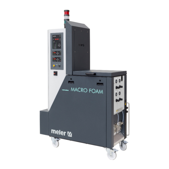
2. INTRODUCTION In this manual you will find information about the installation, use and maintenance of the hot-melt adhesive melter in meler’s Macro Foam series. The Macro series includes the 35, 50 and 120 liter range of hot-melt adhesive melters. -
Page 14: Description
– cover a wide range of applications, being very versatile in all markets where they are used. Intended use The hot-melt melters in the Macro Foam series are designed to be used in the following conditions: • Hot-melt adhesive fusion and pumping at temperatures up to 200°C. -
Page 15: Hot-Melt Melter Identification
INTRODUCTION MA-5127-ENG MACRO FOAM SERIES MELTER MANUAL Control of internal pumping and external pressure_Switches in the position ok ‘int’ and ref ’ext’. This mode of operation is performed through internal pumping control and pressure control by means of an external 0-10 V signal sent from the main machine. -
Page 16: Main Components
FOCKE MELER GLUING SOLUTIONS, S.A. INTRODUCTION Main components... - Page 17 INTRODUCTION MA-5127-ENG MACRO FOAM SERIES MELTER MANUAL 1. Access door to the electronic section and connections. 2. Front control card. 3. Pumping control card 1. 4. Pumping control card 2. 5. Control system of the external adhesive feeding (optional). 6. Main power switch.
-
Page 18: Control Card Components
FOCKE MELER GLUING SOLUTIONS, S.A. INTRODUCTION Control card components 1. Temperature OK LED and pumping allow. 2. Tank indicator LED. 3. Distribuitors indicators LEDS. 4. Temperature set point. 5. Real temperature. 6. ON/OFF switch. 7. Standby function. 8. Time scheduling. -
Page 19: Pumping Control Card Components
INTRODUCTION MA-5127-ENG MACRO FOAM SERIES MELTER MANUAL Pumping control card components 1. Main switch ON/OFF. 2. External start-stop LED. 3. External speed control LED. 4. Pumping permission LED. 5. Up/down arrow keys for selecting values. 6. Left/right arrow keys for selecting options. -
Page 20: Optional Equipment
FOCKE MELER GLUING SOLUTIONS, S.A. INTRODUCTION Optional Equipment In order to provide the melting equipment with more functions, the following optional elements may be added: • Low melted adhesive level detection system. • Light tower system. • Automatic tank filling system. -
Page 21: Installation
Introduction The Macro Foam series melters are delivered with all the materials necessary for their installation. However, some components must be provided by the user himself, according to the location and connections in each particular installation: •... -
Page 22: Electrical Consumption
1510 mm 1875 mm Electrical Consumption In order to install a Macro Foam series melter, we should take into consideration the total consumption of the installation, including the consumption of the installed hoses and applicators. Before connecting, make sure that the voltage that is being connected to the melter is the correct one appearing on the equipment’s characteristics plate. -
Page 23: Unpacking
• Connector for external I/O (included on the power card). Mounting the equipment The Macro Foam series melting equipment are equipped with wheels for their easy transport and positioning near the main machine. The four wheels turn 360°, and two are equipped with brakes. To move the unit, unlock the two wheels by lifting the lever. -
Page 24: Electrical Power Connection
FOCKE MELER GLUING SOLUTIONS, S.A. INSTALLATION Electrical power connection Macro Foam series melters are designed to be connected to the electrical power supply in 3-phase 400 VAC with neutral. A good ground connection is required in any case. Consumption figures, according to melter and output configuration, are included in the table. -
Page 25: Pneumatic Connection
Hose and applicator connection Macro Foam series melters use standard Meler components. The entire range of Meler hoses and applicators may be connected to this equipment. Up to four hose-applicator outputs may be connected to 50 and 120L Macro Foam melters, depending on the number of pumps installed. -
Page 26: Parameter Programming
Once the melter and its components are installed, you will need to program the operational parameters appropriate for the specific application that will be performed. Macro Foam series melters simplify this task as much as possible, allowing the operator to modify only those parameters that are necessarily variable for each application. -
Page 27: Keeping A Component On Display
INSTALLATION MA-5127-ENG MACRO FOAM SERIES MELTER MANUAL 2. Using the right arrow, we advance to the next screen where the º C º C overheating symbol appears. 3. Select the desired value with the up-down arrow. The value displayed corresponds to the increase in real temperature over the set point temperature permitted without activating the alarm message. -
Page 28: External I/O Connections
FOCKE MELER GLUING SOLUTIONS, S.A. INSTALLATION External I/O connections The melter’s input and output signals (I/O) allow it to communicate with the main machine simply and directly. There are seven signals that may be used to communicate with the main machine: •... -
Page 29: External Standby
INSTALLATION MA-5127-ENG MACRO FOAM SERIES MELTER MANUAL 3. Connect the two wires from the start-up signal to the terminals XTOK1 and XTOK2. This is a double terminal, which makes it necessary to connect each wire in one of the two holes in the terminal. Since this contact is not under voltage, there is no connection polarity. -
Page 30: Output Inhibitor
FOCKE MELER GLUING SOLUTIONS, S.A. INSTALLATION 3. Connect the two wires from the start-up signal to the terminals XLD1 and XLD2. This is a double terminal, which makes it necessary to connect each wire in one of the two holes in the terminal. Since this contact is not under voltage, there is no connection polarity. -
Page 31: Starting Up The Motor (Ok Ext)
INSTALLATION MA-5127-ENG MACRO FOAM SERIES MELTER MANUAL Starting up the motor (ok ext) 1. If this is the only signal being connected, use 0.5 mm two-wire cable. 2. Thread the power cord (max. Ø12.5 mm) through the electrical wall Pg13 bushing Pg13 and fasten it to the inside anchor, making sure that the cord reaches the power card connector. -
Page 32: Failures Output In Pump Control Card
FOCKE MELER GLUING SOLUTIONS, S.A. INSTALLATION Failures output in pump control card 1. If this is the only signal being connected, use 0.5 mm two-wire cable. 2. Thread the power cord (max. Ø12.5 mm) through the electrical wall Pg13 bushing Pg13 and fasten it to the inside anchor, making sure that the cord reaches the power card connector. -
Page 33: External Adhesive Feeder
INSTALLATION MA-5127-ENG MACRO FOAM SERIES MELTER MANUAL External adhesive feeder 1. If this is the only signal being connected, use 0.5 mm two-wire cable. 2. Thread the power cord (max. Ø12.5 mm) through the electrical wall Pg13 bushing Pg13 and fasten it to the inside anchor, making sure that the cord reaches the power card connector. - Page 34 FOCKE MELER GLUING SOLUTIONS, S.A. INSTALLATION This page is intentionally left blank. 3-14...
-
Page 35: Melter Operation
MELTER OPERATION MA-5127-ENG MACRO FOAM SERIES MELTER MANUAL 4. MELTER OPERATION In this section we will introduce the method for using the melter. Although its operation is very simple, it should not be used by untrained personnel. Warning: Improper use may cause damage to the machine or injury and even death to the person using it. -
Page 36: Starting Up The Melter Equipment
FOCKE MELER GLUING SOLUTIONS, S.A. MELTER OPERATION To fill the tank: 1. Open the tank lid. 2. Use a shovel or a ladle to fill the tank with adhesive. Do not fill the tank above the loading opening level. The lid must be able to close normally. -
Page 37: Melter Equipment Displays
MELTER OPERATION MA-5127-ENG MACRO FOAM SERIES MELTER MANUAL While the system is running the delay timer both LEDs remains blinking until 1 6 0 1 6 0 1 5 7 1 5 7 the programmed time value has been reached. If then, any other element has not reached 3°... -
Page 38: Displaying The Temperature For Each Component
FOCKE MELER GLUING SOLUTIONS, S.A. MELTER OPERATION Displaying the temperature for each component The temperature may be displayed for each component (premelter, tank, distributor and each hose and applicator) by selecting the component with the cursor. Press the left-right arrow until the desired component is displayed. -
Page 39: Alarm Displays
MA-5127-ENG MACRO FOAM SERIES MELTER MANUAL Alarm displays Macro Foam series melter equipment tell the user when a malfunction has occurred in the unit, sending warning messages that may be seen on the control panel display. When an alarm appears, the control unit takes a series of steps to protect the unit. -
Page 40: Hot-Melt Display Level (Optional)
FOCKE MELER GLUING SOLUTIONS, S.A. MELTER OPERATION Hot-melt display level (optional) If the equipment is fitted with a level detector, and the hot-melt level drops below the programmed level (capacitive detector), a signal is sent to the melter control which launches the following actions: 1. -
Page 41: Programming The Applicator Parameters
MELTER OPERATION MA-5127-ENG MACRO FOAM SERIES MELTER MANUAL The general process for adjusting the temperatures of each components is described below. 1. Select the component whose value you wish to modify using the left- right arrow. The tank and the distributor have the same set point value. -
Page 42: Setting The Clock
FOCKE MELER GLUING SOLUTIONS, S.A. MELTER OPERATION The value shown corresponds to the percent decrease in the real temperature compared to the set point temperature that will occur when this function is activated. 7. Use the right arrow to go to the next display where delay time value appears. -
Page 43: Programming Equipment Activation/Deactivation
MELTER OPERATION MA-5127-ENG MACRO FOAM SERIES MELTER MANUAL On the left display, you will see the time with a dot, indicating that this . 0 8 . 0 8 is the value that may be modified, while the minutes appear on the second display. -
Page 44: Disabling The Equipment Activation/Deactivation Program
FOCKE MELER GLUING SOLUTIONS, S.A. MELTER OPERATION 4. The blinking dot next to the start time indicates that this is the value 0 7 . 2 0 7 . 2 1 9 . 3 1 9 . 3 that may be modified. Use the up-down arrow to select the desired value. -
Page 45: Programming The Equipment's Standby Function Activation/Deactivation
MELTER OPERATION MA-5127-ENG MACRO FOAM SERIES MELTER MANUAL Programming the equipment’s standby function activation/deactivation You may program an activation and a deactivation time for every day of the week, from Monday (1) to Sunday (7). Time is expressed in 15 minute increments, so we cycle from 10.0 (10 hours and 0 minutes) to 10.1 (10 hours... -
Page 46: Disabling The Equipment Standby Function Programming
FOCKE MELER GLUING SOLUTIONS, S.A. MELTER OPERATION 8. Press the button with the clock symbol once again. The selected program appears once again. You may use the up-down arrow to select other programs. 9. Pressing either the left or the right arrow button will exit this program and return to the tank temperature display. -
Page 47: Special Function Buttons
MELTER OPERATION MA-5127-ENG MACRO FOAM SERIES MELTER MANUAL Special function buttons The simplicity of programming Macro Foam system series melters reduces the use of the special function buttons to only the standby function. This manual function allows you to alternate between the operational mode and the standby mode. -
Page 48: Pumping Control
FOCKE MELER GLUING SOLUTIONS, S.A. MELTER OPERATION Pumping control Starting up the pump control card The pump control card (hereingafter also control card), features an ON-OFF button that allows us to turn off the displays and LEDs (leaving on only the 24... -
Page 49: Password Security
MELTER OPERATION MA-5127-ENG MACRO FOAM SERIES MELTER MANUAL • Whenever an error occurs, the control disables pumping (red ON-OFF button LED is illuminated) and prevents the operation of the pump until the error is reset, the pumping ON-OFF button is pressed again and the red LED turns off. -
Page 50: Led Indicators
FOCKE MELER GLUING SOLUTIONS, S.A. MELTER OPERATION LED indicators Described below are the LED indicators on the pump control card to identify the status of the equipment: 1. Control card ON/OFF LED: when the external 24 Vdc power supply is present, this LED will always be illuminated;... -
Page 51: Modes Of Operation
MELTER OPERATION MA-5127-ENG MACRO FOAM SERIES MELTER MANUAL Modes of operation First of all, we must bear in mind that when password security is enabled and the control card is not manipulated during one minute, it is blocked and you need to enter the password. -
Page 52: Mode Of Operation With Internal Pumping Control And External Pressure Control
FOCKE MELER GLUING SOLUTIONS, S.A. MELTER OPERATION The maximum full scale for admissible pressure is 85 bar. This full scale can be adjusted by reducing this value in percentage terms. To make adjustments consult the ‘User configuration menu’, ‘1. MAXIMUM PRESSURE ALARM’. -
Page 53: Mode Of Operation With External Pumping Control And Internal Pressure Control
MELTER OPERATION MA-5127-ENG MACRO FOAM SERIES MELTER MANUAL Keeping the ‘Vin’ key pressed will show the voltage sent by the main machine. The pump will stop whenever: • The control card is disabled with its ON/OFF button. • The pumping ON-OFF button is pressed (red LED is illuminated). -
Page 54: Mode Of Operation With External Pumping Control And External Pressure Control
FOCKE MELER GLUING SOLUTIONS, S.A. MELTER OPERATION The system will wait for the pumping control signal from the main machine. If a work pressure has been previously set, this value will be shown on the display and the pump will start to work at the pressure indicated provided that all prior conditions are met. - Page 55 MELTER OPERATION MA-5127-ENG MACRO FOAM SERIES MELTER MANUAL To activate the start-up status, all of the following conditions must be met: • That the signal from the main machine reaches input E2 and its value is not 0. • That the input for pumping permission (E4) at central control is activated, as pumping is not possible unless the equipment temperature is OK.
-
Page 56: User Configuration Menu
FOCKE MELER GLUING SOLUTIONS, S.A. MELTER OPERATION The pump control card is designed with certain parameters programmed at Meler that can be modified if necessary to meet your requirements. Modifications may be made through the ‘User configuration menu’ and programming pressure curve menus. -
Page 57: Displaying Alarms And Reset Function
MELTER OPERATION MA-5127-ENG MACRO FOAM SERIES MELTER MANUAL Displaying alarms and reset function Maximum pressure alarm This alarm will be triggered when the pump work at a pressure exceeding the MAXIMUM PRESSURE ALARM value for the period established in the MAXIMUM PRESSURE ALARM TIME field. - Page 58 FOCKE MELER GLUING SOLUTIONS, S.A. MELTER OPERATION By default the table is programmed (0 V = 0 bar and 10 V = 85 bar): P P r r e e s s s s u u r r e e...
-
Page 59: Programming Pressure Curve
MELTER OPERATION MA-5127-ENG MACRO FOAM SERIES MELTER MANUAL Programming pressure curve To access this menu and program the different points corresponding to the voltage- pressure ratio, you must select external reference (‘ref ext’ LED is illuminated) and press the right arrow key. Then the following message is displayed: The IN LED to the position ON and the OUT LED to the position OFF, 1 000, NOT EDITABLE;... -
Page 60: Current Vin Voltage Display
FOCKE MELER GLUING SOLUTIONS, S.A. MELTER OPERATION Current Vin voltage display Whenever the Vin key is held pressed, the three digits on the right will show the input voltage reading to one decimal point. If the values for any point in the pressure curve table is being edited, and the Vin key is held pressed for 3 seconds, the voltage value which is operating at this time it will be copied to that value on the table. -
Page 61: Loader Off Function
MELTER OPERATION MA-5127-ENG MACRO FOAM SERIES MELTER MANUAL Low level detection Launching the feeder Detection of the correct level Stopping the feeder System refilled Start of the over-level timing Loader OFF function If you want to disable the automatic pellet feeder, push and hold the OFF button for 3 seconds. -
Page 62: Level Sensor Adjustments
FOCKE MELER GLUING SOLUTIONS, S.A. MELTER OPERATION Level sensor adjustments Sensitivity adjustment The adjustable sensitivity of the sensor, depending on the material used and the hysteresis admitted to the operation of the vacuum feeder is factory pre- setted and therefore it is NOT necessary to change. In most cases the factory setting is perfectly valid to use the vacuum feeder. -
Page 63: Setting Programmable Times Using The Timer
MELTER OPERATION MA-5127-ENG MACRO FOAM SERIES MELTER MANUAL Pressing the amber light button the system will be resetted. The security time will begin to count again. You just have to press the reset button after having corrected the existing failures: Obstruction of aspiration hose. -
Page 64: Manual Feeding
FOCKE MELER GLUING SOLUTIONS, S.A. MELTER OPERATION Manual feeding For production needs or if there is any fault in the level detector it is possible to do manual loading. In this case the automatic feeder must be in inhibition mode (by pressing for 3 seconds stop button). -
Page 65: Maintenance
Check thermostats operating - Checking while working Thermostats maintenance If the equipment does not work or works incorrectly, called to your Meler Representative or to the Main Office. Equipment cleaning To continue to take advantage of the melter’s benefits and to ensure the perfect mobility of its components, it is necessary to keep all its parts clean, especially the ventilation grate on the upper part of the machine. -
Page 66: Depressurizing The System
FOCKE MELER GLUING SOLUTIONS, S.A. MAINTENANCE Removing and changing exterior panels: 1. Disconnect the melter equipment. 2. Disconnect the compressed air from the equipment intake. 3. Turn counterclockwise 1/4 turn the two screws holding the panel. 4. Tilt the panel and pull it up by means of two handles placed below fixing screws. -
Page 67: Tank Grating
MAINTENANCE MA-5127-ENG MACRO FOAM SERIES MELTER MANUAL No rule exists for determining when to change the filter. Several factors influence this decision: • The type and purity of the adhesives used. • The adhesive work temperatures. • Adhesive consumption in relation to the time it spends in the tank. -
Page 68: Tank Filter
FOCKE MELER GLUING SOLUTIONS, S.A. MAINTENANCE Tank filter At the manifolds input there is a coarse filter inside the tank itself. This filter acts as a first step stoping dirty and parts from the outside. This filter includes an output to empty the tank for cleaning it or changing the adhesive. -
Page 69: Cleaning Burnt Adhesive
MAINTENANCE MA-5127-ENG MACRO FOAM SERIES MELTER MANUAL Cleaning burnt adhesive 1. Empty the tank directly (see the section ‘Emptying the tank’) to prevent the burnt material from passing through the pump circuit. 2. Clean the adhesive remains and burnt material inside the tank. Do not use sharp objects that might damage the inside coating. -
Page 70: Pump Maintenance
FOCKE MELER GLUING SOLUTIONS, S.A. MAINTENANCE 4. Lower the discharge ramp located next to the tank and put an appropriate container in place. 5. Unscrew the emptying plug and allow the adhesive to flow freely into the container. 6. Once completely empty, clean the any remaining adhesive from around the output hole and ramp. -
Page 71: Gas Injection Valve Cleaning
MAINTENANCE MA-5127-ENG MACRO FOAM SERIES MELTER MANUAL Gas injection valve cleaning Once depressurised the system and at a pump temperature of around 80-100 ºC, release the two screws securing the gas valve to the pump. Then remove the gas valve, and disassemble it. -
Page 72: Thermostats Maintenance
FOCKE MELER GLUING SOLUTIONS, S.A. MAINTENANCE Thermostats maintenance If one of the two existing thermostats is deactivated, follow these instructions to reset them: 1. Remove the side plate, as shown in the image. 2. Lift the insulating blanket and locate the thermostats. -
Page 73: Technical Characteristics
TECHNICAL CHARACTERISTICS MA-5127-ENG MACRO FOAM SERIES MELTER MANUAL 6. TECHNICAL CHARACTERISTICS General Tank capacity 35 liters / 50 liters 120 liters Pumping rate (*) single pump 1.6 ; 3.3; 6.6 cc/rev 1.6 ; 3.3; 6.6 cc/rev Melting rate (*) 35kg/h - 50 kg/h... -
Page 74: Dimensions
FOCKE MELER GLUING SOLUTIONS, S.A. TECHNICAL CHARACTERISTICS Dimensions Macro 50 1150 Macro 120 1150... -
Page 75: Electrical Drawings
ELECTRICAL DRAWINGS MA-5127-ENG MACRO FOAM SERIES MELTER MANUAL 7. ELECTRICAL DRAWINGS... - Page 76 FOCKE MELER GLUING SOLUTIONS, S.A. ELECTRICAL DRAWINGS This page is intentionally left blank.
-
Page 77: Pneumatic Diagrams
PNEUMATIC DIAGRAMS MA-5127-ENG MACRO FOAM SERIES MELTER MANUAL 8. PNEUMATIC DIAGRAMS Components list Pneumatic by-pass valve control system Pressure regulator 1-10 bar. Pressure gauge 0-10 bar. Pneumatic limit control valve. REGULADOR DE PRESIÓN MANÓMETRO PRESSURE REGULATOR MANOMETER P: 0-10 bar P: 0-10 bar VÁLVULA LIMITADORA / PRESSURE LIMIT VALVE... - Page 78 FOCKE MELER GLUING SOLUTIONS, S.A. PNEUMATIC DIAGRAMS This page is intentionally left blank.
-
Page 79: Spare Parts List
MACRO FOAM SERIES MELTER MANUAL 9. SPARE PARTS LIST The most common spare parts list of the Macro Foam series adhesive melters is shown in this chapter to give you a quick and sure guideline to choose them. The spare parts are listed by groups in a natural order as they are located on the units. -
Page 80: Cover- Tank Assembly Macro Foam
FOCKE MELER GLUING SOLUTIONS SPARE PARTS LIST A. COVER- TANK ASSEMBLY MACRO FOAM 35 Nº Ref. Description 150113240 Tank seal PTFE 7X2,5 150110140 Capacitive detector 10030007 Current connection strip 150010130 O-ring Ø16x2 150027960 Pump 3/4” plug 16h UNF with O-ring 150028830 Tank grid (micrón 32) -
Page 81: Cover- Tank Assembly
HOJA Nº/ MACRO 50 SHEET NUMBER 1 de 1 Este plano es propiedad exclusiva de MELER APLICADORES DE HOT - MELT S.A. Todos los derechos rese This drawing is owned sole of MELER APLICADORES DE HOT- MELT S.A. All rights reserved. -
Page 82: Distributor Assembly
FOCKE MELER GLUING SOLUTIONS SPARE PARTS LIST C. DISTRIBUTOR ASSEMBLY Nº Ref. Description 150113200 O-ring Ø80 x 2 150023950 O-ring 24x2 10100082 Pump plug 10100083 Pump plug O-ring 150027960 Pump 3/4” plug 16h UNF with O-ring 150041920 O-ring 3/4” 150027970 Heating element 3/8”... -
Page 83: Filter/Purge And Pressure Valve Assembly
SPARE PARTS LIST MA-5127-ENG MACRO FOAM SERIES MELTER MANUAL D. FILTER/PURGE AND PRESSURE VALVE ASSEMBLY Nº Ref. Description 150026270 Pneumatic pressure valve assembly 150026060 Pressure valve closure needle 150026300 Pneumatic pressure valve o-rings 150091090 Pressure transducer 150029250 Distributor filter cartridge... -
Page 84: Geared Motor-Pump Assembly
FOCKE MELER GLUING SOLUTIONS SPARE PARTS LIST E. GEARED MOTOR-PUMP ASSEMBLY Nº Ref. Description 150119570 Single gear pump 6.6 cc/rev V1 2016 150119100 Single gear pump 3.3 cc/rev V1 2016 150119580 Single gear pump 1.6 cc/rev V1 2016 150119350 Single gear pump 3.3 cc/rev 1:2.5 2016 150119980 Single gear pump 9.9 cc/rev 1:2.5 2016... -
Page 85: Electrical Cabinet
SPARE PARTS LIST MA-5127-ENG MACRO FOAM SERIES MELTER MANUAL F. ELECTRICAL CABINET Nº Ref. Description 150091370 Motor inverter G110 0.55kW 150091580 Motor inverter G110 1.1kW 150091590 Motor inverter G110 1.5kW 150113680 Power control board 6 outputs 150024710 Sensor board Pt100/Ni120... - Page 86 FOCKE MELER GLUING SOLUTIONS SPARE PARTS LIST 29 30...
-
Page 87: Ec Declaration Of Conformity
EC DECLARATION OF CONFORMITY Original Declaration The manufacturer, Focke Meler Gluing Solutions, S.A. Pol. Los Agustinos, c/G, nave D-43 E-31160 Orkoien, Navarra - Spain — Focke Group — declaring that the machinery, Type: Model: Serial Number: fulfils all the relevant provisions of the Directive 2006/42/EC on machinery,... - Page 88 For more information speak with your Focke Meler representative: Focke Meler Gluing Solutions, S.A. Pol. Arazuri-Orkoien, c/B, nº3 A E-31170 Arazuri - Navarra - Spain Phone: +34 948 351 110 info@meler.eu - www.meler.eu Focke Group...
Need help?
Do you have a question about the MACRO FOAM Series and is the answer not in the manual?
Questions and answers