
Related Manuals for Meler MICRON NON STOP


Summary of Contents for Meler MICRON NON STOP
- Page 1 GLUING SOLUTIONS ADHESIVE INSTRUCTIONS MANUAL MELTER MICRON NON STOP MA-5147-ENG 151220...
- Page 2 Published by: Focke Meler Gluing Solutions, S. A. Pol. Arazuri-Orkoien, c/B, nº3 A E-31170 Arazuri - Navarra - Spain Tel.: + 34 948 351 110 e-mail: info@meler.eu www.meler.eu Focke Group Edition December 2020 © Copyright by Focke Meler All rights reserved. Its reproduction, diffusion or use by electronic or other means of all or any part of this document without the express authorization of its owner is strictly prohibited.
-
Page 3: Table Of Contents
TABLE OF CONTENTS MA-5147-ENG MICRON NON STOP ADHESIVE MELTER TABLE OF CONTENTS 1. SAFETY GUIDELINES General Symbols Mechanical components Electrical components Hydraulic components Pneumatic components Thermal components Materials Noise emission declaration Intended use Limited use 2. INTRODUCTION Description Modes of operation... - Page 4 FOCKE MELER GLUING SOLUTIONS TABLE OF CONTENTS Electrical Consumption Compressed air Other factors Unpacking Contents Mounting the equipment Electrical power connection Pneumatic connection Hose and applicator connection Parameter Programming Programming working temperatures Selecting the overheating value Keeping a component on display...
- Page 5 TABLE OF CONTENTS MA-5147-ENG MICRON NON STOP ADHESIVE MELTER Password to access parameter programming 4-13 Total equipment service hours counter 4-13 Counter that warns of the need to change the adhesive agent filter 4-14 Setting the clock 4-15 Programming the current day and hour...
- Page 6 FOCKE MELER GLUING SOLUTIONS TABLE OF CONTENTS Operating modes 4-31 By-pass valve regulation 4-34 Adjusting the sensitivity of the capacitive sensors 4-34 Turning off the melter equipment 4-35 5. MAINTENANCE Equipment cleaning System depressurisation Access to the interior of the equipment...
- Page 7 TABLE OF CONTENTS MA-5147-ENG MICRON NON STOP ADHESIVE MELTER Optional equipment Wheel system 7. ELECTRICAL DRAWINGS 8. PNEUMATIC DIAGRAM Components list Pneumatic cylinder control system Pneumatic by-pass valve control system 9. SPARE PART LIST A. TANK ASSEMBLY B. DISTRIBUTOR SIMPLE/ DOUBLE ASSEMBLY C.
- Page 8 FOCKE MELER GLUING SOLUTIONS TABLE OF CONTENTS This page is intentionally left blank.
-
Page 9: Safety Guidelines
SAFETY GUIDELINES MA-5147-ENG MICRON NON STOP ADHESIVE MELTER 1. SAFETY GUIDELINES General The information contained in this section applies not only to everyday equipment operation, but also to any procedure carried out on it, whether for preventive maintenance or in the case of repairs and the replacement of worn out parts. -
Page 10: Mechanical Components
FOCKE MELER GLUING SOLUTIONS SAFETY GUIDELINES Mechanical components The hot-melt installation, which is installed to this device, requires moving parts that can cause damage. Use the equipment correctly, and do not remove the safety guards while the equipment is in operation; prevent the risk of possible entrapment due to moving mechanical parts. -
Page 11: Thermal Components
Safety Information Sheet of the adhesive. Materials Focke Meler systems are designed for use with hot-melt adhesives. They should not be used with any other type of material, and especially not with solvents, which may cause personal injury or damage to internal system components. -
Page 12: Intended Use
Note: Do not modify the equipment or use components that were not supplied by Focke Meler. For any modification of a component of the equipment or part of the installation, you must firstly consult the After-Sales Service... -
Page 13: Introduction
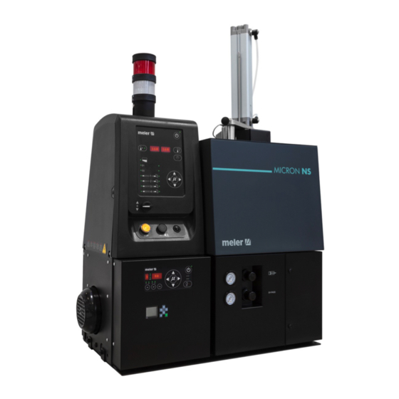
2. INTRODUCTION This manual contains information on installing, using and maintaining the Micron Non Stop adhesive melter from Focke Meler. This equipment is designed to melt 2 kilo blocks of adhesive (Ø128 mm and height 165 mm). It has a 0.87 litre reserve tank. -
Page 14: Description
FOCKE MELER GLUING SOLUTIONS INTRODUCTION Description These melters are designed for use with Focke Meler hoses and applicators in hot-melt adhesive applications. Their different variations – line, coating or swirl-spray – cover a wide range of applications, being very versatile in all markets where they are used. -
Page 15: Hot-Melt Melter Identification
INTRODUCTION MA-5147-ENG MICRON NON STOP ADHESIVE MELTER Hot-melt melter identification When placing orders for replacement parts or requesting help from our Technical Service, you should know the model and reference number of your hot-melt melter. This and other technical information will be found on the identification plate located on the side of the lower part of the hot-melt melter. -
Page 16: Control Card Components
FOCKE MELER GLUING SOLUTIONS INTRODUCTION Control card components 1. Tank indicator LED. 2. Applicator indicator LED. 3. Temperature set point. 4. Real temperature. 5. ON/OFF switch. 6. Standby function. 7. Temperature OK LED. 8. Time scheduling. 9. Left/right button - channel selection. -
Page 17: Pumping Control Card Components
INTRODUCTION MA-5147-ENG MICRON NON STOP ADHESIVE MELTER Pumping control card components 1. Main switch ON/OFF. 2. External start-stop LED. 3. External speed control LED. 4. Pumping permission LED. 5. Up/down arrow keys for selecting values. 6. Left/right arrow keys for selecting options. -
Page 18: Logo Programmer
1. Display. 2. Keys to move the cursor / select values. 3. OK key to select / confirm. 4. ESC key (Exit). Micron Non Stop series range MICRON pump ON/OFF switch - SW: with pump switch ON/OFF connector low level warning light -... -
Page 19: Installation
INSTALLATION MA-5147-ENG MICRON NON STOP ADHESIVE MELTER 3. INSTALLATION Warning: The melters are equipment with current technology and with certain foreseeable risks. Therefore, only allow qualified personnel with enough training and experience to use, install or repair this equipment. Introduction The melters of this serie are delivered with all the materials necessary for their installation. -
Page 20: Electrical Consumption
FOCKE MELER GLUING SOLUTIONS INSTALLATION To calculate the space necessary to install the equipment in terms of its length, you must add at least 280 mm to the measurements indicated in the table in order to be able to open the distributor’s purger access door and release the pusher cylinder. -
Page 21: Compressed Air
MA-5147-ENG MICRON NON STOP ADHESIVE MELTER Compressed air The installation of melters Micron Non Stop requires a non-lubricated compressed air dryer system with a maximum pressure of 6 bar to supply the pusher disk cylinder and the pneumatic bypass valve. -
Page 22: Mounting The Equipment
Slide the unit to its final position. Lock the wheels once again, lowering the levers. Electrical power connection Micron Non Stop melters are designed to be connected to the electrical power supply with 3-phases 400 VAC with neutral. A good ground connection is required always. -
Page 23: Pneumatic Connection
Focke Meler hoses and applicators may be connected to this equipment. Up to four hose-applicator outputs may be connected. Micron Non Stop melters are equipped with a simple or double hydraulic distributor with four posibilities of hydraulic connection. The outputs are not numered so the hoses can be connected to the distributor in any order. -
Page 24: Parameter Programming
Once the melter and its components are installed, you will need to program the operational parameters appropriate for the specific application that will be performed. Micron Non Stop simplify this task as much as possible, allowing the operator to modify only those parameters that are necessarily variable for each application. -
Page 25: Selecting The Overheating Value
INSTALLATION MA-5147-ENG MICRON NON STOP ADHESIVE MELTER This simple process must be repeated for each one of the components installed on the melter. Selecting the overheating value 1. Press the buttons with the clock symbol and the down arrow at the same time to enter the special menu. -
Page 26: External I/O Connections
FOCKE MELER GLUING SOLUTIONS INSTALLATION 2. Hold the arrow button down for two seconds, selecting the desired component. 3. The display will now remain on the selected component, without changing. 4. Simple press any left-right arrow button again to restore the default display (tank). - Page 27 INSTALLATION MA-5147-ENG MICRON NON STOP ADHESIVE MELTER Adhesive bag empty Output that connects the main machine (or to a warning light tower) that the Output XT1 / XT2 adhesive bag is finished. The unit can continue operating while it has a level of adhesive in the tank.
-
Page 28: Output Disabled
FOCKE MELER GLUING SOLUTIONS INSTALLATION Warning: It must be connected to 24 AC or DC voltage with a maximum current of 500mA. If you connect this signal to 230V load current cannot be less than 50mA. Output disabled 1. If this is the only signal being connected, use a seven-wire cable no smaller than 0.22 mm... -
Page 29: Melter Operation
MELTER OPERATION MA-5147-ENG MICRON NON STOP ADHESIVE MELTER 4. MELTER OPERATION In this section we will introduce the method for using the melter. Although its operation is very simple, it should not be used by untrained personnel. Warning: Improper use may cause damage to the machine or injury and even death to the person using it. -
Page 30: Filling The Tank
Warning: Before refilling the cylinder, ensure that the adhesive is the same type as the existing one. Mixing different types of adhesive may damage the melter. The Micron Non Stop melter has a tank capacity of 0.87 litres. -
Page 31: Starting Up The Melter Equipment
(see Chapter ‘2. Introduction. Operating modes’). Melter equipment displays Micron Non Stop melters have two displays built into their control panel, with three sets of 7 segments each for displaying the temperature values (set point and real temperature), programmable parameters and alarms. -
Page 32: Displaying The Temperature For Each Component
FOCKE MELER GLUING SOLUTIONS MELTER OPERATION They are equipped with LED indicators to display the heating of each component, as well as the pump activations and the main machine connection signal: LED display Component heating Component status constantly lit constant... -
Page 33: Alarm Displays
MELTER OPERATION MA-5147-ENG MICRON NON STOP ADHESIVE MELTER The following is the display sequence: distributor<—tank<—hose1<—applicator1<—¡…<—hose4<—applicator4 distributor—>tank—>hose1—>applicator1—>…—>hose4—>applicator4 For units that have two pumps installed, the display sequence is the following: null<—tank<—distributor1<—Off<—distributor2<—Off<—hose1 <—applicator1<—…<—hose4<—applicator4 null—>tank—>distributor1—>Off—>distributor2—>Off—>hose1 —>applicator1—>…—>hose4—>applicator4 To remove a component from permanent display, simply press either of the left-right arrows. - Page 34 FOCKE MELER GLUING SOLUTIONS MELTER OPERATION Actions Code Source Heating Pump Main machine signal tank broken sensor only tank off distributor broken sensor only distributor off null null null hose1 broken sensor only hose1 off applicator1 broken sensor only applicator1 off...
-
Page 35: Display And Adjustment Of The Cylinder Working Temperature
MELTER OPERATION MA-5147-ENG MICRON NON STOP ADHESIVE MELTER Display and adjustment of the cylinder working temperature In this equipment, the air pressure with which the pusher cylinder pneumatic control device operates is shown on the pressure gauge located on the base of the melter. -
Page 36: Programming The Applicator Parameters
FOCKE MELER GLUING SOLUTIONS MELTER OPERATION 1. Select the component whose value you wish to modify using the left- right arrow. The tank and the distributor have the same set point value The corresponding LED will blink rapidly. 2. Select the desired set point temperature value with the up-down arrow. -
Page 37: Programming Process
MELTER OPERATION MA-5147-ENG MICRON NON STOP ADHESIVE MELTER Modify value To select the function to be programmed, press the right arrow to advance through the various functions. Once selected, the buttons up and down modify the value. Pressing the arrow right again the data is stored and passed to the next function. - Page 38 FOCKE MELER GLUING SOLUTIONS MELTER OPERATION 8. Use the up-down arrow to select the desired value (between 0 and 60 min). 9. Use the right arrow to advance to the next screen, where the level detector activation/deactivation is found. 10. Use the up-down arrow to select the desired value (ON/OFF). When OFF is selected, neither the on-screen display nor the external signal activation will be operational.
- Page 39 MELTER OPERATION MA-5147-ENG MICRON NON STOP ADHESIVE MELTER 17. Use the right arrow to go to the next display. This function is a counter that registers total hours of equipment operation, that is, with service temperature OK enabled. This is an increment counter and its value cannot be modified.
-
Page 40: Timer To Switch Between On - Standby - Off Modes
FOCKE MELER GLUING SOLUTIONS MELTER OPERATION Timer to switch between ON - Standby - OFF modes This function is used to program automatic switching from the ON mode to Standby mode after an inactive period of time (S-1) and from STANDBY mode to OFF mode after another waiting period (S-2) during which activity has not been resumed. -
Page 41: Password To Access Parameter Programming
MELTER OPERATION MA-5147-ENG MICRON NON STOP ADHESIVE MELTER Password to access parameter programming A Password can be programmed to protect access to certain equipment programming functions by unauthorised users. The special menu can be used to program a value between 000 (disabled) and 999. -
Page 42: Counter That Warns Of The Need To Change The Adhesive Agent Filter
FOCKE MELER GLUING SOLUTIONS MELTER OPERATION Counter that warns of the need to change the adhesive agent filter This function is a partial countdown counter that registers the hours of equi- pment operation, that is, with service temperature OK activated, from tP1000 hours to tP0000 hours. -
Page 43: Setting The Clock
MA-5147-ENG MICRON NON STOP ADHESIVE MELTER Setting the clock Micron Non Stop melters are equipped with a weekly programmable system controlling equipment connection and disconnection and activating and deactivating the standby function. Before programming these functions, it is necessary to introduce into the control unit data corresponding to the day and hour used to execute these programs. -
Page 44: Programming Equipment Activation/Deactivation
FOCKE MELER GLUING SOLUTIONS MELTER OPERATION Programming equipment activation/deactivation You may program an activation and a deactivation time for every day of the week, from Monday (1) to Sunday (7). Time is expressed in 15 minute increments, so we cycle from 10.0 (10 hours and 0 minutes) to 10.1 (10 hours and 15 minutes) to 10.2 (10 hours and 30... -
Page 45: Disabling The Equipment Activation/Deactivation Program
MELTER OPERATION MA-5147-ENG MICRON NON STOP ADHESIVE MELTER Disabling the equipment activation/deactivation program It is possible to disable the equipment activation/deactivation programming without canceling the daily programming. This way the programmed data is saved, but the programming will have no effect on the equipment. -
Page 46: Disabling The Equipment Standby Function Programming
FOCKE MELER GLUING SOLUTIONS MELTER OPERATION 4. Press the button with the clock symbol once again. Two times will appear, one in each display. The left display shows the start time, while the right display shows the finish time. 5. The blinking dot next to the start time indicates that this is the time that may be modified. -
Page 47: Special Function Buttons
Special function buttons The simplicity of programming Micron Non Stop melters/applicators reduces the use of the special function buttons to only the standby function. This manual function allows you to alternate between the operational mode and the standby mode. -
Page 48: Pumping Control
FOCKE MELER GLUING SOLUTIONS MELTER OPERATION Pumping control Starting up the pump control card The pump control card (hereingafter also control card), features an ON-OFF button that allows us to turn off the displays and LEDs (leaving on only the 24... -
Page 49: Password Security
MELTER OPERATION MA-5147-ENG MICRON NON STOP ADHESIVE MELTER • Whenever an error occurs, the control disables pumping (red ON-OFF button LED is illuminated) and prevents the operation of the pump until the error is reset, the pumping ON-OFF button is pressed again and the red LED turns off. -
Page 50: Led Indicators
FOCKE MELER GLUING SOLUTIONS MELTER OPERATION LED indicators Described below are the LED indicators on the pump control card to identify the status of the equipment: 1. Control card ON/OFF LED: when the external 24 Vdc power supply is present, this LED will always be illuminated; with no power supply, it will be turned off. -
Page 51: Modes Of Operation
MELTER OPERATION MA-5147-ENG MICRON NON STOP ADHESIVE MELTER Modes of operation First of all, we must bear in mind that when password security is enabled and the control card is not manipulated during one minute, it is blocked and you need to enter the password. -
Page 52: Mode Of Operation With Internal Pumping Control And External Speed Control
FOCKE MELER GLUING SOLUTIONS MELTER OPERATION Mode of operation with internal pumping control and external speed control In this operating mode, pumping is controlled from the equipment and speed is controlled by a 0-10 V external signal from the main machine. -
Page 53: Mode Of Operation With External Pumping Control And Internal Speed Control
MELTER OPERATION MA-5147-ENG MICRON NON STOP ADHESIVE MELTER Mode of operation with external pumping control and internal speed control In this operating mode, pumping is controlled from the main machine while speed is controlled from the equipment. Follow the steps below to use this operating mode: 1. -
Page 54: Mode Of Operation With External Pumping Control And External Speed Control
FOCKE MELER GLUING SOLUTIONS MELTER OPERATION Mode of operation with external pumping control and external speed control In this working mode, both pumping and speed are controlled from the main machine. Follow the steps below to use this operating mode: 1. -
Page 55: User Configuration Menu
‘User configuration menu’, ‘1. MAXIMUM RPM’. The pump control card is designed with certain parameters programmed at Focke Meler that can be modified if necessary to meet your requirements. Modifications may be made through the user configuration and programming speed ramp menus. -
Page 56: Displaying Alarms And Reset Function
FOCKE MELER GLUING SOLUTIONS MELTER OPERATION Displaying alarms and reset function Maximum rpm alarm This alarm will be triggered when the motor rotates at a speed exceeding the MAXIMUM RPM ALARM value for the period established in the MAXIMUM RPM ALARM TIME field. -
Page 57: Configuring Speed Ramp
MELTER OPERATION MA-5147-ENG MICRON NON STOP ADHESIVE MELTER Configuring speed ramp For equipment operating in external reference, the display will show the current pump rotation set point (input reference conversion as per the full scale and the conversion table). The conversion table may be programmed with up to 5 points (input voltage (V) and output speed (RPM)). -
Page 58: Programming Speed Ramp
FOCKE MELER GLUING SOLUTIONS MELTER OPERATION Programming speed ramp To access this menu and program the different points corresponding to the voltage- speed ratio, you must select external reference (‘ref ext’ LED is illuminated) and press the right arrow key. Then the following message is displayed: The IN LED to the position ON and the OUT LED to the position OFF, 1 000, NOT EDITABLE;... -
Page 59: Current Vin Voltage Display
MELTER OPERATION MA-5147-ENG MICRON NON STOP ADHESIVE MELTER Current Vin voltage display Whenever the Vin key is held pressed, the three digits on the right will show the input voltage reading to one decimal point. If the values for any point in the speed ramp table is being edited, and the Vin key is held pressed for 3 seconds, the voltage value which is operating at this time it will be copied to that value on the table. - Page 60 FOCKE MELER GLUING SOLUTIONS MELTER OPERATION 2. Monitoring of the adhesive level in the lower tank. The machine’s lower tank has two capacitive sensors. The upper sensor signal manages the adhesive level and the lower sensor signal produces the low level alarm.
- Page 61 MELTER OPERATION MA-5147-ENG MICRON NON STOP ADHESIVE MELTER 6. Warnings and alarms. Warnings table: the tank lid warnings have priority and when they are active the remainder of the warnings are not shown. The screen light activates in orange. Viewing warnings...
-
Page 62: By-Pass Valve Regulation
FOCKE MELER GLUING SOLUTIONS MELTER OPERATION By-pass valve regulation The pumping system using a geared pump provides a constant flow of adhesive, according to the pump’s rotational speed. In this type of system, the pressure generated by the pump is the result of the retentions found on the circuit (the length and diameter of the hose, elbows in the connectors, the diameters of the nozzle outputs, etc.) and the adhesive... -
Page 63: Turning Off The Melter Equipment
MELTER OPERATION MA-5147-ENG MICRON NON STOP ADHESIVE MELTER 3. Gently turn the adjusting screw ¼ turn counterclockwise. The LED will change back to green. It is recommended to carry out a verification of the signals once the equipment is in automatic operation. - Page 64 FOCKE MELER GLUING SOLUTIONS MELTER OPERATION This page is intentionally left blank. 4-36...
-
Page 65: Maintenance
MAINTENANCE MA-5147-ENG MICRON NON STOP ADHESIVE MELTER 5. MAINTENANCE Warning: The melter equipment is equipped with current technology, but has certain foreseeable risks. Therefore, only allow qualified personnel with enough training and experience to operate install or repair this equipment. - Page 66 FOCKE MELER GLUING SOLUTIONS MAINTENANCE To carry out external cleaning: • Use cleaning products compatible with polyamide materials. • Apply the cleaning product with a soft cloth. • Do not use sharp tools or scrapers with sharp edges. Removing and changing exterior panels: 1.
-
Page 67: System Depressurisation
MICRON NON STOP ADHESIVE MELTER System depressurisation The Micron Non Stop melter is a pressurised application system with the corresponding risks that such a system entails. This equipment includes a safety valve (bypass valve) which limits the maximum pressure in the system, particularly during continuous pumping with closed application applicators. -
Page 68: Cleaning The Tank
FOCKE MELER GLUING SOLUTIONS MAINTENANCE Cleaning the tank Both the cylindrical hopper and hot-melt tank will need cleaning occasionally to maintain their melting and anti-adherence properties. The tank interior is covered in PTFE and sufficiently slanted to help the unloading of the hot-melt adhesive and prevent it from remaining inside which would result in burning. -
Page 69: Emptying The Tank
1. Add cleaner adhesive on the grill cover and wait to melt it, without pressing cylinder. Warning: The Micron Non Stop is ready to melt the adhesive blocks, so if the pellets are poured into he grill and press with the cylinder, probably the adhesive cleaner go out from the sides and as a consequence on the top (see the picture). -
Page 70: Cleaning Capacitive Sensors
Before making any changes, establish the location of the leak. However, before replacing any parts and in case of any doubt, we recommend that you consult the Focke Meler Technical Service Centre. Warning: Always wear protective gloves and goggles. Risk of burns. -
Page 71: Gear Motor Maintenance
MAINTENANCE MA-5147-ENG MICRON NON STOP ADHESIVE MELTER Gear motor maintenance Cleaning the motor fan Periodically inspect the condition of the motor fan and its vent screen. If dust has accumulated, blow gently with air to clean it (remove the protective cover, if necessary). - Page 72 FOCKE MELER GLUING SOLUTIONS MAINTENANCE 2. Depressurise the system (1). 3. Disconnect the hoses connected to the distributor outputs both electrically and hydraulically. 4. Disconnect the input power supply and ground connection. 5. Raise the machine to extract it from the base.
-
Page 73: Technical Characteristics
TECHNICAL CHARACTERISTICS MA-5079-ENG MICRON GEAR ADHESIVE MELTER 6. TECHNICAL CHARACTERISTICS General Holding capacity For using 128 mm diameter adhesive blocks Tank reservoir capacity 870 cc (max. level); 210 cc (alarm level) Maximum pumping rate From 6 to 48 cm simple pump 1, 2.5, 4 or 8 cm double pump 2x0.93, 2x1.86, 2x3.71, 2x4.8 cc/rev (*) -
Page 74: Dimensions
FOCKE MELER GLUING SOLUTIONS TECHNICAL CHARACTERISTICS Dimensions 775+250 Optional equipment Wheel system For hese equipments there is the option to add 4 wheels to the base of the machine to make it easier to move. -
Page 75: Electrical Drawings
ELECTRICAL DRAWINGS MA-5147-ENG MICRON NON STOP ADHESIVE MELTER 7. ELECTRICAL DRAWINGS... - Page 76 FOCKE MELER GLUING SOLUTIONS ELECTRICAL DRAWINGS This page is intentionally left blank.
-
Page 77: Pneumatic Diagram
PNEUMATIC DIAGRAM MA-5147-ENG MICRON NON STOP ADHESIVE MELTER 8. PNEUMATIC DIAGRAM Components list Pneumatic cylinder control system Inlet filter (filtering disk). Pressure regulator. Pressure gauge. Pneumatic valve 5/2. Pneumatic cylinder. Exhaust port filter. -
Page 78: Pneumatic By-Pass Valve Control System
FOCKE MELER GLUING SOLUTIONS PNEUMATIC DIAGRAM Pneumatic by-pass valve control system Pressure regulator 1-10 bar. Pressure gauge 0-10 bar. Pneumatic limit control valve. AIR INPUT... -
Page 79: Spare Part List
MICRON NON STOP ADHESIVE MELTER 9. SPARE PART LIST The list of the most common spare parts for Micron Non Stop machines appears in this section, providing a quick and reliable guide to choosing them. The spare parts are grouped together naturally, in the same way as they are located in the melters. - Page 80 FOCKE MELER GLUING SOLUTIONS SPARE PARTS LIST This page is intentionally left blank.
- Page 81 SPARE PARTS LIST MA-5147-ENG MICRON NON STOP ADHESIVE MELTER CHASSIS ASSEMBLY AND WARNING LIGHT TANK ASSEMBLY ELECTRIC/ELECTRONIC ASSEMBLY DISTRIBUTOR ASSEMBLY GEARED MOTOR- PUMP ASSEMBLY PNEUMATIC COMPONENTS Formación requerida EQUIPO ZAPATOS GUANTES GAFAS OTROS Calidad Producción Piezas en pr MANTENER ORDEN Y LIMPIEZA...
-
Page 82: Tank Assembly
FOCKE MELER GLUING SOLUTIONS SPARE PARTS LIST A. TANK ASSEMBLY Nº Ref. Description 150130110 Pneumatic cylinder 150028100 Retractable positioner 150025830 Inductive sensor M5x0.5 150113820 Tank heating element 750W 150114620 Safety thermostat 200°C 150022650 Tank sensor Ni-120 150022640 Tank sensor Pt-100... -
Page 83: Distributor Simple/ Double Assembly
SPARE PARTS LIST MA-5147-ENG MICRON NON STOP ADHESIVE MELTER B. DISTRIBUTOR SIMPLE/ DOUBLE ASSEMBLY Nº Ref. Description 150026270 Pneumatic pressure regulator 150026300 Pneumatic pressure regulator o-rings 150121380 Head with purger 150026330 Purger assembly 150029260 O-ring Ø23x3 150026340 O-ring Ø7x1,5 150121350... -
Page 84: Geared Motor-Pump Assembly
FOCKE MELER GLUING SOLUTIONS SPARE PARTS LIST C. GEARED MOTOR-PUMP ASSEMBLY Nº Ref. Description 150117170 Geared motor 0,375 KW with booster fun 150117150 Simple pump motor coumpling 150117160 Double pump motor coumpling 150026430 Simple pump o-rings Double pump o-rings 150111890... -
Page 85: Chassis Assembly And Warning Light
SPARE PARTS LIST MA-5147-ENG MICRON NON STOP ADHESIVE MELTER D. CHASSIS ASSEMBLY AND WARNING LIGHT Nº Ref. Description 150130130 Eectrical cabinet door casing 150113360 Electrical cabinet casing assembly with warning light 150130140 Tank housing assembly R0006220 Lamp 24V... -
Page 86: Electric/Electronic Assembly
FOCKE MELER GLUING SOLUTIONS SPARE PARTS LIST E. ELECTRIC/ELECTRONIC ASSEMBLY Nº Ref. Description 150113660 Control board Micron 150113670 Power board Micron 2 outlets 150113680 Power board Micron 6 outlets 150024710 Sensor board Micron Pt100/Ni120 150110970 Fuse 0,315A 5x20 150117100 Pump control board... -
Page 87: Electric/Electronic Assembly
SPARE PARTS LIST MA-5147-ENG MICRON NON STOP ADHESIVE MELTER E. ELECTRIC/ELECTRONIC ASSEMBLY... -
Page 88: Pneumatic Components
FOCKE MELER GLUING SOLUTIONS SPARE PARTS LIST F. PNEUMATIC COMPONENTS Nº Ref. Description 150114040 Pressure gauge 10110031 Pressure regulator 150110730 Pneumatic limit valve 150060090 Solenoid valve 4/2 1/8” 24 VDC 12,7W 150060170 Solenoid valve 5/3 9-10... -
Page 89: Ec Declaration Of Conformity
EC DECLARATION OF CONFORMITY Original Declaration The manufacturer, Focke Meler Gluing Solutions, S.A. Pol. Arazuri-Orkoien, c/B, nº3 A E-31170 Arazuri - Navarra - Spain — Focke Group — declaring that the machinery, Type: Model: Serial Number: fulfils all the relevant provisions of the Directive 2006/42/EC on machinery,... - Page 90 For more information speak with your Focke Meler representative: Focke Meler Gluing Solutions, S.A. Pol. Arazuri-Orkoien, c/B, nº3 A E-31170 Arazuri - Navarra - Spain Phone: +34 948 351 110 info@meler.eu - www.meler.eu Focke Group...
Need help?
Do you have a question about the MICRON NON STOP and is the answer not in the manual?
Questions and answers