Meler Micron 5 Instruction Manual
Micron piston series
Hide thumbs
Also See for Micron 5:
- Instruction manual (42 pages) ,
- Quick start manual (2 pages) ,
- Instruction manual (108 pages)

Related Manuals for Meler Micron 5


Summary of Contents for Meler Micron 5
- Page 1 GLUING SOLUTIONS ADHESIVE INSTRUCTIONS MANUAL MELTER MICRON PISTON SERIES MA-5078-ENG 090218...
- Page 2 The specifications and information contained in this manual may be modified without prior notice. This manual is a translation of the original that was written by Focke Meler Gluing Solutions, S. A. in spanish language. If there is any discrepancy between the different versions of this manual, the original written in the spanish language shall prevail.
-
Page 3: Table Of Contents
TABLE OF CONTENTS MA-5078-ENG MICRON PISTON ADHESIVE MELTER MANUAL TABLE OF CONTENTS 1. SAFETY GUIDELINES General Symbols Mechanical components Electrical components Hydraulic components Pneumatic components Thermal components Materials Noise emission declaration Intended use Limited use 2. INTRODUCTION Description Modes of operation Hot-melt melter/applicator identification Main components Control card components... - Page 4 FOCKE MELER GLUING SOLUTIONS TABLE OF CONTENTS 3. INSTALLATION Introduction Installation requirements Electrical Consumption Compressed air Other factors Unpacking Contents Mounting the equipment Electrical power connection Pneumatic connection Hose and applicator connection Parameter Programming Programming working temperatures Selecting the overheating value...
- Page 5 TABLE OF CONTENTS MA-5078-ENG MICRON PISTON ADHESIVE MELTER MANUAL Hot-melt display level (optional) Operational pressure display and adjustment Temperature adjustment Programming the applicator parameters Programming process Timer to switch between ON - Standby - OFF modes 4-11 Password to access parameter programming 4-12 Total equipment service hours counter 4-12...
- Page 6 FOCKE MELER GLUING SOLUTIONS TABLE OF CONTENTS 6. TROUBLESHOOTING Melter The unit does not turn on Equipment shortcircuit malfunction Tank The tank does not heat The tank does not stop heating Temperature fluctuations in the tank Manifold The manifold does not heat...
- Page 7 TABLE OF CONTENTS MA-5078-ENG MICRON PISTON ADHESIVE MELTER MANUAL 7. TECHNICAL CHARACTERISTICS Generals Dimensions Accessories Low level detection system Wheel system Adaptation plate for previous models 8. ELECTRICAL DRAWINGS 9. PNEUMATIC DIAGRAM Components list 7 cm /stroke pump 19 cm /stroke pump With electro-pneumatic pressure regulator VP Pneumatic connection for 7 cm...
- Page 8 FOCKE MELER GLUING SOLUTIONS TABLE OF CONTENTS 10. SPARE PARTS LIST 10-1 A. TANK ASSEMBLY 10-4 B. DISTRIBUTOR UNIT 10-5 C. PUMP ASSEMBLY 10-6 D. PNEUMATIC UNIT ASSEMBLY 7cc 10-7 D. PNEUMATIC UNIT ASSEMBLY 19cc 10-8 E. CHASSIS ASSEMBLY 10-9 F.
-
Page 9: Safety Guidelines
SAFETY GUIDELINES MA-5078-ENG MICRON PISTON ADHESIVE MELTER MANUAL 1. SAFETY GUIDELINES General The information contained in this section applies not only to everyday equipment operation, but also to any procedure carried out on it, whether for preventive maintenance or in the case of repairs and the replacement of worn out parts. -
Page 10: Mechanical Components
FOCKE MELER GLUING SOLUTIONS SAFETY GUIDELINES Mechanical components The hot-melt installation, which is installed to this device, requires moving parts that can cause damage. Use the equipment correctly, and do not remove the safety guards while the equipment is in operation; prevent the risk of possible entrapment due to moving mechanical parts. -
Page 11: Thermal Components
Safety Information Sheet of the adhesive. Materials Meler systems are designed for use with hot-melt adhesives. They should not be used with any other type of material, and especially not with solvents, which may cause personal injury or damage to internal system components. -
Page 12: Intended Use
Note: Do not modify the equipment or use components that were not supplied by Meler. For any modification of a component of the equipment or part of the installation, you must firstly consult the After-Sales Service... -
Page 13: Introduction
MICRON PISTON ADHESIVE MELTER MANUAL 2. INTRODUCTION In this manual you will find information about the installation, use and maintenance of the hot-melt adhesive melter/applicator in meler’s micron series. The ‘micron’ series includes the 5, 10, 20 and 35 liter range of hot-melt adhesive melters/applicators. -
Page 14: Description
INTRODUCTION Description The ‘micron’ are designed for use with ‘meler’ hoses and applicators in hot- melt adhesive applications. Their different variations – line, coating or swirl- spray – cover a wide range of applications, being very versatile in all markets where they are used. -
Page 15: Main Components
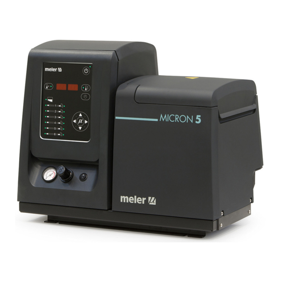
INTRODUCTION MA-5078-ENG MICRON PISTON ADHESIVE MELTER MANUAL Main components 1. Front control card 2. Access door to the electric/pneumatic area 3. Tank access lid 4. Pump air pressure regulator 5. Air pressure gauge 6. Characteristics plate 7. Main switch 8. Hose output distributor (up to 6 hydraulic connections) 9. -
Page 16: Control Card Components
FOCKE MELER GLUING SOLUTIONS INTRODUCTION Control card components 1. Tank indicator LED 2. Applicator indicator LED 3. Temperature set point 4. Real temperature 5. ON/OFF switch 6. Standby function 7. Temperature OK LED 8. Time scheduling 9. Left/right button - channel selection 10. -
Page 17: Micron Series Range
INTRODUCTION MA-5078-ENG MICRON PISTON ADHESIVE MELTER MANUAL MICRON series range MICRON 400N proportional pressure system - VP0: without VP / VP1 with VP low level warning light - B0: no warning light / B1: with warning cover model - V: standard / CG: automatic feeder power supply voltage** - 400N: 3x400+N+T / 400: 3x400+T pump flow* -... -
Page 18: Micron Range Option Accessories
FOCKE MELER GLUING SOLUTIONS INTRODUCTION MICRON range option accessories If some of the different machine configuration options have been chosen, it will be necessary to purchase the following accessories separately: 400N or 400 power supply voltage option The transformer for the 5, 10 and 20l machine must be requested separately. -
Page 19: Installation
INSTALLATION MA-5078-ENG MICRON PISTON ADHESIVE MELTER MANUAL 3. INSTALLATION Warning: The melters/applicators are equipment with current technology and with certain foreseeable risks. Therefore, only allow qualified personnel with sufficient training and experience to use, install or repair this equipment. Introduction The ‘micron’... -
Page 20: Electrical Consumption
FOCKE MELER GLUING SOLUTIONS INSTALLATION Item Description Dimension 588 mm 671 mm EQUIPMENT LENGTH 671 mm 742 mm 339 mm 339 mm EQUIPMENT WIDTH 383 mm 435 mm 481 mm 481 mm EQUIPMENT HEIGHT 526 mm 673 mm 628 mm... -
Page 21: Other Factors
Communicate any defect, even to the outer packing materials, to your ‘meler’ Representative or to the Main Office. Contents The ‘micron’ series packing materials may contain accessories that form part of the same order. -
Page 22: Electrical Power Connection
• 3-phases 400 VAC with neutral. A good ground connection is required in all cases. Consumption figures, according to melter/applicator and output configuration, are included in the table. Due to high power connected ‘meler’ recommends 3-phases 400 VAC with neutral connection. Equipment No. -
Page 23: Pneumatic Connection
INSTALLATION MA-5078-ENG MICRON PISTON ADHESIVE MELTER MANUAL L3 N PE L1 L2 L3 N PE LN~230V 50/60Hz + PE 3N~400V 50/60Hz + PE WITHOUT NEUTRAL L1 L2 L3 PE 3~230V 50/60Hz + PE Consumption values concerning each equipment can be found in the characteristics plate. -
Page 24: Hose And Applicator Connection
FOCKE MELER GLUING SOLUTIONS INSTALLATION Hose and applicator connection ‘micron’ series melters/applicators use standard ‘meler’ components. The entire range of ‘classic’, ‘compact’ and ‘manual’ hoses and applicators may be connected to this equipment. Up to six hose-applicator outputs may be connected to 5, 10, 20 and 35L ‘micron’... -
Page 25: Selecting The Overheating Value
INSTALLATION MA-5078-ENG MICRON PISTON ADHESIVE MELTER MANUAL • 160 °C for the tank and the distributor • 150 ºC for hoses and 160 ºC for applicators The general process for modifying set up temperature values for any component is described below. 1. -
Page 26: Keeping A Component On Display
FOCKE MELER GLUING SOLUTIONS INSTALLATION Keeping a component on display By default, the main display shows the tank temperatures. However, it is possible to display indefinitely the temperatures of any component for analysis or tracking. 1. Select the component you wish to see permanently with the left-right arrow. -
Page 27: External Standby
INSTALLATION MA-5078-ENG MICRON PISTON ADHESIVE MELTER MANUAL Install an electrical wall bushing Pg13.5 on the equipment base plate next to the electrical supply input. 2. Open the door to the electrical cabinet as far as possible. Thread the power cord (max. Ø12.5mm) through the electrical wall bushing Pg13.5 and fasten it to the inside anchor, making sure that the cord reaches the power card connector at the position where it will be installed (CN 1). -
Page 28: Low Level (Optional)
FOCKE MELER GLUING SOLUTIONS INSTALLATION Low level (optional) 1. If this is the only signal being connected, use 0.5 mm two-wire cable. Install an electrical wall bushing Pg13.5 on the equipment base plate next to the electrical supply input. 2. Open the door to the electrical cabinet as far as possible. Thread the power cord (max. - Page 29 INSTALLATION MA-5078-ENG MICRON PISTON ADHESIVE MELTER MANUAL 4 input for disabled output 3 5 input for disabled output 4 8 7 6 5 4 3 2 1 6 input for disabled output 5 7 input for disabled output 6 8 without connection 4.
- Page 30 FOCKE MELER GLUING SOLUTIONS INSTALLATION This page is intentionally left blank. 3-12...
-
Page 31: Melter Operation
MELTER OPERATION MA-5078-ENG MICRON PISTON ADHESIVE MELTER MANUAL 4. MELTER OPERATION In this section we will introduce the method for using the melter/applicator. Although its operation is very simple, it should not be used by untrained personnel. Warning: Improper use may cause damage to the machine or injury and even death to the person using it. -
Page 32: Filling The Tank
FOCKE MELER GLUING SOLUTIONS MELTER OPERATION Filling the tank The tank can be equipped with a floating-type low level sensor (optional) that warns when the level of hot-melt adhesive drops below a third of the tank’s capacity. The unit will activate the external signal and, if it is connected, the corresponding warning device. -
Page 33: Melter/Applicator Equipment Displays
MELTER OPERATION MA-5078-ENG MICRON PISTON ADHESIVE MELTER MANUAL 2. Press the ON/OFF button on the control card to turn it on, if it not already activated. By default, the set point and real temperature values shown are those corresponding to the tank. The tank heating control LED (green) will light up and the tank will begin to heat. -
Page 34: Displaying The Temperature For Each Component
FOCKE MELER GLUING SOLUTIONS MELTER OPERATION Displaying the temperature for each component The temperature may be displayed for each component (tank, distributor and each hose and applicator) by selecting the component with the cursor. Press the left-right arrow until the desired component is displayed. -
Page 35: Hot-Melt Display Level (Optional)
MELTER OPERATION MA-5078-ENG MICRON PISTON ADHESIVE MELTER MANUAL Actions Code Source Heating Pump Main machine signal Err 103 hose2 overheating all components off Err 104 applicator2 overheating all components off Err 105 hose3 overheating all components off Err 106 applicator3 overheating all components off Err 107 hose4 overheating... -
Page 36: Operational Pressure Display And Adjustment
FOCKE MELER GLUING SOLUTIONS MELTER OPERATION Operational pressure display and adjustment The air pressure with which the pneumatic pump control device works with is shown on the pressure gauge located on the base of the melter/applicator. The pressure must be adjusted according to the application needs. -
Page 37: Programming The Applicator Parameters
MELTER OPERATION MA-5078-ENG MICRON PISTON ADHESIVE MELTER MANUAL Programming the applicator parameters The access to the parameters is performed from the special menu. Simulta- neously press the buttons with the clock symbol and the down arrow to enter this menu. The navigation order is as follows: Symbol on the dis- Function Default value... - Page 38 FOCKE MELER GLUING SOLUTIONS MELTER OPERATION 3. Use the right arrow to move to the next display where the overheating symbol appears. 4. Select the desired value (between 10 and 25) using the up-down arrow. The value shown corresponds to the increase in real temperature allowed over the set point temperature without activating the alarm message.
- Page 39 MELTER OPERATION MA-5078-ENG MICRON PISTON ADHESIVE MELTER MANUAL 12. Use the up-down arrow to select the desired value (see ‘Timer to switch between ON - Standby - OFF modes’). 13. Use the right arrow to go to the next display. 14.
- Page 40 FOCKE MELER GLUING SOLUTIONS MELTER OPERATION 18. Use the right arrow to go to the next display. 19. Use the up-down arrow to select the desired value (see ‘Counter that warns of the need to change the adhesive agent filter’).
-
Page 41: Timer To Switch Between On - Standby - Off Modes
MELTER OPERATION MA-5078-ENG MICRON PISTON ADHESIVE MELTER MANUAL Timer to switch between ON - Standby - OFF modes This function is used to program automatic switching from the ON mode to Standby mode after an inactive period of time (S-1) and from STANDBY mode to OFF mode after another waiting period (S-2) during which activity has not been resumed. -
Page 42: Password To Access Parameter Programming
FOCKE MELER GLUING SOLUTIONS MELTER OPERATION Password to access parameter programming A Password can be programmed to protect access to certain equipment pro- gramming functions by unauthorised users. The special menu can be used to program a value between 000 (disabled) and 999. -
Page 43: Counter That Warns Of The Need To Change The Adhesive Agent Filter
MELTER OPERATION MA-5078-ENG MICRON PISTON ADHESIVE MELTER MANUAL Counter that warns of the need to change the adhesive agent filter This function is a partial countdown counter that registers the hours of equi- pment operation, that is, with service temperature OK activated, from tP1000 hours to tP0000 hours. -
Page 44: Setting The Clock
FOCKE MELER GLUING SOLUTIONS MELTER OPERATION Setting the clock ‘micron’ series melters are equipped with a weekly programmable system controlling equipment connection and disconnection and activating and deac- tivating the standby function. Before programming these functions, it is necessary to introduce into the control unit data corresponding to the day and hour used to execute these programs. -
Page 45: Programming Equipment Activation/Deactivation
MELTER OPERATION MA-5078-ENG MICRON PISTON ADHESIVE MELTER MANUAL Programming equipment activation/deactivation You may program an activation and a deactivation time for every day of the week, from Monday (1) to Sunday (7). Time is expressed in 15 minute increments, so we cycle from 10.0 (10 hours and 0 minutes) to 10.1 (10 hours and 15 minutes) to 10.2 (10 hours and 30 minutes) to 10.3 (10 hours and 45 minutes). -
Page 46: Disabling The Equipment Activation/Deactivation Program
FOCKE MELER GLUING SOLUTIONS MELTER OPERATION Disabling the equipment activation/deactivation program It is possible to disable the equipment activation/deactivation programming without canceling the daily programming. This way the programmed data is saved, but the programming will have no effect on the equipment. -
Page 47: Disabling The Equipment Standby Function Programming
MELTER OPERATION MA-5078-ENG MICRON PISTON ADHESIVE MELTER MANUAL 4. Press the button with the clock symbol once again. Two times will appear, one in each display. The left display shows the start time, while the right display shows the finish time. 5. -
Page 48: Special Function Buttons
FOCKE MELER GLUING SOLUTIONS MELTER OPERATION 4. Press the button with the clock symbol once again. The status will alternate each time you press the button. 5. Pressing either the left or the right arrow button will exit this program and return to the tank temperature display. -
Page 49: Turning Off The Melter/Applicator Equipment
MELTER OPERATION MA-5078-ENG MICRON PISTON ADHESIVE MELTER MANUAL Turning off the melter/applicator equipment If you need to disconnect the melter/applicator equipment: 1. Turn off the machine switch on the door of the electrical cabinet next to the pressure regulator. The depressurization valve frees pressure from the hydraulic circuit, returning the adhesive to the tank. - Page 50 FOCKE MELER GLUING SOLUTIONS MELTER OPERATION This page is intentionally left blank. 4-20...
-
Page 51: Maintenance
MAINTENANCE MA-5078-ENG MICRON PISTON ADHESIVE MELTER MANUAL 5. MAINTENANCE Warning: The melter/applicator equipment is equipped with current technology, but has certain foreseeable risks. Therefore, only allow qualified personnel with enough training and experience to operate install or repair this equipment. The following table briefly summarizes the indications for adequate melter/ applicator equipment maintenance. -
Page 52: System Depressurisation
The lid and the casing are removed from the tank at the same time. 7. The tank lid of Micron 5 and 10 is removed once the tank casing has been dismantled. It is simply a matter of sliding the shafts at the ends along the grooves in the casing. -
Page 53: Access To Pneumatic Unit
MAINTENANCE MA-5078-ENG MICRON PISTON ADHESIVE MELTER MANUAL The depressurization valve releases the pressure from the hydraulic circuit, returning the adhesive to the tank. 2. Purge all applicators that have been used either manually or with the corresponding program command. Access to pneumatic unit To access the unit for more exhaustive machine maintenance, it will be necessary to remove the electrical cabinet from its place so it can be handled more comfortably and accessibly. -
Page 54: Cleaning The Tank
FOCKE MELER GLUING SOLUTIONS MAINTENANCE Warning: Always use protective gloves and goggles. Risk of burns. To change the filter, it should be borne in mind that the filter and purge valve are the same assembly: 1. Depressurise the system. 2. To remove the whole filter, unscrew the assembly’s hexagonal plug using a 22mm socket driver and remove it. -
Page 55: Cleaning Burnt Adhesive
In the case of the Micron 5, the tank does not have a pouring chute so, to empty out the adhesive you need to wait until it has cooled and separate it from the walls of the tank, making it easier to remove. -
Page 56: Safety Thermostat
FOCKE MELER GLUING SOLUTIONS MAINTENANCE 4. Unscrew the plug and allow the adhesive to flow freely into the container. 5. Once it is completely empty, clean the exit hole and chute of remains of adhesive. 6. Put the plug back in position. -
Page 57: Troubleshooting
If you do not reach the cause follow to the next problem. If you are unable to solve the problem with the help provided in this chapter, contact your Area Technical Service Center or ‘meler’ headquarter directly. -
Page 58: Melter
FOCKE MELER GLUING SOLUTIONS TROUBLESHOOTING Melter The unit does not turn on Causes Checking Comments Actions Check voltage between phases Check wiring. Equipment power and neutrals in the main Voltages will vary depending Check net power supply. supply malfunction. terminal. Check voltage in CN4 on power supply. -
Page 59: The Tank Does Not Stop Heating
TROUBLESHOOTING MA-5078-ENG MICRON PISTON ADHESIVE MELTER MANUAL Causes Checking Comments Actions Release the fuse to check it Tank fuse blown. Check fuse continuity (F01). out with the system turned Change fuse. off. Check wiring, it might be Power board Check CN6 connector voltage Correct if voltage is around wrong positioned. -
Page 60: Manifold
FOCKE MELER GLUING SOLUTIONS TROUBLESHOOTING Manifold The manifold does not heat Causes Checking Comments Actions Check voltage between phases Check wiring. Equipment power Voltages will vary depending and neutrals.Check voltage in Check net power supply. supply malfunction. on power supply. -
Page 61: Pump
TROUBLESHOOTING MA-5078-ENG MICRON PISTON ADHESIVE MELTER MANUAL Pump The shaft is not moving (the pressure gauge shows no pressure reading) Causes Checking Comments Actions If no pressure, the Check the pressure in the regulator Change pressure No air pressure. manometer will show zero and net pressure. -
Page 62: Adhesive Leaks
FOCKE MELER GLUING SOLUTIONS TROUBLESHOOTING Causes Checking Comments Actions Quick pumping occurs in two Change Depressurization valve Check if adhesive returns through direction but without having a depressurization malfunction. the valve (system under pressure). continuous adhesive output. valve. Adhesive leaks... -
Page 63: Temperature Fluctuations In Hose
TROUBLESHOOTING MA-5078-ENG MICRON PISTON ADHESIVE MELTER MANUAL Temperature fluctuations in hose Causes Checking Comments Actions Hose temperature Replace the hose by another one Change hose channel. Change hose. sensor malfunction. that works. Check sensor board and hose CN* sensor board connector Sensor wiring. -
Page 64: Temperature Fluctuations In Applicator
FOCKE MELER GLUING SOLUTIONS TROUBLESHOOTING Temperature fluctuations in applicator Causes Checking Comments Actions Applicator Replace the applicator by temperature sensor Change applicator channel. Change applicator. another one that works. malfunction. Check sensor board and CN* sensor board connector Sensor wiring. -
Page 65: Lay Out Power Board
TROUBLESHOOTING MA-5078-ENG MICRON PISTON ADHESIVE MELTER MANUAL LAY OUT POWER BOARD CN10 DL10 CN11 DL11 DL12 DL14 DL13 CN9,CN10 and CN11 Channel 2, 4 or 6 Channel 1, 3 or 5 Applicator Tank Common Hose Distributor... -
Page 66: Lay Out Control Board
FOCKE MELER GLUING SOLUTIONS TROUBLESHOOTING LAY OUT CONTROL BOARD LAY OUT SENSOR BOARD CN11 Distributor Tank CN2, CN3, CN4, CN5, CN6,CN7 Applicator Hose 6-10... -
Page 67: Technical Characteristics
TECHNICAL CHARACTERISTICS MA-5078-ENG MICRON PISTON ADHESIVE MELTER MANUAL 7. TECHNICAL CHARACTERISTICS Generals Tank capacity 5,15 liters 9,7 liters Pumping rate 29,3 kg/h 7cc/stroke pump (*) 29,3 kg/h 7cc/stroke pump (*) 66,0 kg/h 19cc/stroke pump (*) 66,0 kg/h 19cc/stroke pump (*) Melting rate 9,0 kg/h (*) 13,5 kg/h (*) - Page 68 FOCKE MELER GLUING SOLUTIONS TECHNICAL CHARACTERISTICS Tank capacity 19,7 liters 37,4 liters Pumping rate 29,3 kg/h 7cc/stroke pump (*) 29,3 kg/h 7cc/stroke pump (*) 66,0 kg/h 19cc/stroke pump (*) 66,0 kg/h 19cc/stroke pump (*) Melting rate 19 kg/h (*) 30 kg/h (*)
-
Page 69: Dimensions
TECHNICAL CHARACTERISTICS MA-5078-ENG MICRON PISTON ADHESIVE MELTER MANUAL Dimensions micron 20 micron 20 micron 10 micron 5, 10, 20 micron 20 micron 35... - Page 70 Note: the indicated holes are for M8 screws. Este plano es propiedad exclusiva de MELER APLICADORES DE HOT - MELT S.A. Todos los derechos reservados. This drawing is owned sole of MELER APLICADORES DE HOT- MELT S.A. All rights reserved.
-
Page 71: Accessories
For the equiment ‘micron’ 35 the adaptation plate does not exist. hacia zonas libres. Ø 9 A: micron 5 equipment set up and replacament of other equipment. B: micron10, micron 20 equipment set up and replacament of other equipment. C: Replacement of ML-240-ST series equipment. - Page 72 FOCKE MELER GLUING SOLUTIONS TECHNICAL CHARACTERISTICS This page is intentionally left blank.
-
Page 73: Electrical Drawings
ELECTRICAL DRAWINGS MA-5078-ENG MICRON PISTON ADHESIVE MELTER MANUAL 8. ELECTRICAL DRAWINGS... - Page 74 FOCKE MELER GLUING SOLUTIONS ELECTRICAL DRAWINGS This page is intentionally left blank.
-
Page 75: Pneumatic Diagram
PNEUMATIC DIAGRAM MA-5078-ESP MICRON PISTON ADHESIVE MELTER MANUAL 9. PNEUMATIC DIAGRAM Components list 7 cm /stroke pump Inlet filter (filtering disk) Solenoid valve 3/2 manual override (230V 50 Hz 1.5VA) Pressure regulator 1-8 bar Pressure gauge 0-10 bar Pneumatic valve 5/2 Differential valve Pneumatic cylinder double acting double chamber Ø50x50 (7cm... - Page 76 FOCKE MELER GLUING SOLUTIONS PNEUMATIC DIAGRAM INSTRUCCION DE MONTAJE DENOMINACION/DENOMINATION REFERENCIA/REFERENCE EDICION MICRON IM0004 Pneumatic connection for 7 cm /stroke PUMP Nº DE HOJAS FECHA/DATE TITULO/TITLE 1 DE 9 6/06/07 NEUMATICA CILINDRO PEQUEÑO INSTALACION NEUMATICA PARA EL GRUPO PEQUEÑO PRESSURE REGULATOR...
- Page 77 PNEUMATIC DIAGRAM MA-5078-ESP MICRON PISTON ADHESIVE MELTER MANUAL Pneumatic diagram for 7 cm /stroke PUMP...
- Page 78 Se elimina la válvula de entrada que lleva incorporado el propio grupo y se sustituye por una de mayor tamaño colocada en el exterior. FOCKE MELER GLUING SOLUTIONS PNEUMATIC DIAGRAM La fijación de esta válvula se realiza mediante fijación al tubo de acero de la válvula de descarga.
- Page 79 PNEUMATIC DIAGRAM MA-5078-ESP MICRON PISTON ADHESIVE MELTER MANUAL Pneumatic diagram for 19 cm /stroke PUMP...
- Page 80 INSTRUCCION DE MONTAJE DENOMINACION/DENOMINATION REFERENCIA/REFERENCE EDICION IM0004 FOCKE MELER GLUING SOLUTIONS PNEUMATIC DIAGRAM Nº DE HOJAS FECHA/DATE TITULO/TITLE 6/06/07 VP CON GRUPO NEUMATICO 7cc Electro-pneumatic connection with pressure regulator VP. 7 cm /stroke PUMP PRESSURE REGULATOR TO PRESSURE DISCHARGE VALVE...
- Page 81 PNEUMATIC DIAGRAM MA-5078-ESP MICRON PISTON ADHESIVE MELTER MANUAL Electro-pneumatic diagram with pressure regulator VP. 7 cm /stroke PUMP...
- Page 82 INSTRUCCION DE MONTAJE FOCKE MELER GLUING SOLUTIONS PNEUMATIC DIAGRAM DENOMINACION/DENOMINATION REFERENCIA/REFERENCE EDICION MICRON IM0004 Nº DE HOJAS FECHA/DATE TITULO/TITLE 9 DE 9 6/06/07 NEUMATICA MICRON VP Electro-pneumatic connection with pressure regulator VP. 19 cm VP CON GRUPO NEUMATICO 19cc /stroke PUMP TUBO NEUMATICO Ø6 (R.55)
- Page 83 PNEUMATIC DIAGRAM MA-5078-ESP MICRON PISTON ADHESIVE MELTER MANUAL Electro-pneumatic diagram with pressure regulator VP. 19 cm /stroke PUMP...
- Page 84 FOCKE MELER GLUING SOLUTIONS PNEUMATIC DIAGRAM This page is intentionally left blank. 9-10...
-
Page 85: Spare Parts List
SPARE PARTS LIST MA-5078-ENG MICRON PISTON ADHESIVE MELTER MANUAL 10. SPARE PARTS LIST The list of the most common spare parts for Micron series machines appears in this section, providing a quick and reliable guide to choosing them. The spare parts are grouped together naturally, in the same way as they are located in the melters. - Page 86 FOCKE MELER GLUING SOLUTIONS SPARE PARTS LIST This page is intentionally left blank. 10-2...
- Page 87 SPARE PARTS LIST MA-5078-ENG MICRON PISTON ADHESIVE MELTER MANUAL CHASSIS GROUP TANK GROUP PUMP ELECTRONIC DISTRIBUTOR GROUP GROUP GROUP PNEUMATIC UNIT ELECTRIC GROUP 10-3...
-
Page 88: Tank Assembly
FOCKE MELER GLUING SOLUTIONS SPARE PARTS LIST A. TANK ASSEMBLY Nº Ref. Description 150113470 Complete tank assembly micron 5 230V 150113480 Complete tank assembly micron 10 230V 150113490 Complete tank assembly micron 20 230V 150114890 Complete tank assembly micron 35 230V... -
Page 89: Distributor Unit
SPARE PARTS LIST MA-5078-ENG MICRON PISTON ADHESIVE MELTER MANUAL B. DISTRIBUTOR UNIT Nº Ref. Description 150026350 Heating element 300 W 10120032 Tank-distributor seating o-ring 150121390 Distributor filter assembly 150121380 Filter head with purger 150029250 Filter mesh 50 150029260 O-ring 23 x 3 150026340 O-ring 7 x 1.5 150121350... -
Page 90: Pump Assembly
FOCKE MELER GLUING SOLUTIONS SPARE PARTS LIST C. PUMP ASSEMBLY Nº Ref. Description 150113550 7cc pump body with braces and fittings 150113560 19cc pump body with braces and fittings 10100011 Pump shaft 7cc 150023080 Pump shaft 19cc 150113570 Tank-pump-distributor seating O-ring kit... -
Page 91: Pneumatic Unit Assembly 7Cc
SPARE PARTS LIST MA-5078-ENG MICRON PISTON ADHESIVE MELTER MANUAL D. PNEUMATIC UNIT ASSEMBLY 7cc Nº Ref. Description 150113610 Pneumatic unit assembly with filter 7cc 150113650 1/4’ flat silencer 150114480 Pressure gauge 10110031 Pressure regulator 150113690 Connector kit for 7cc pump unit without VP 150020490 Differential valve with o-ring 150020500... -
Page 92: Pneumatic Unit Assembly 19Cc
FOCKE MELER GLUING SOLUTIONS SPARE PARTS LIST D. PNEUMATIC UNIT ASSEMBLY 19cc Nº Ref. Description 150113620 Pneumatic unit assembly 19cc with filter 150114480 Pressure gauge 10110031 Pressure regulator 150113850 Connector kit for 19cc pump unit without VP 150111730 Solenoid coil (220V AC) 19cc... -
Page 93: Chassis Assembly
Micron electrical cabinet door casing 150113290 Electrical cabinet casing assembly without warning light 150113360 Electrical cabinet casing assembly with warning light 150113300 Micron 5 tank housing assembly 150113310 Micron 10 tank housing assembly 150113320 Micron 20 tank housing assembly 150114950... -
Page 94: Electronic Assembly
FOCKE MELER GLUING SOLUTIONS SPARE PARTS LIST F. ELECTRONIC ASSEMBLY Nº Ref. Description 150113660 Control board micron 150113670 Power board micron 2 outlets 150113680 Power board micron 6 outlets 150024710 Sensor board Pt100/Ni120 micron 150110970 Fuse 0,315A 5x20 R0002393 Capacitor... -
Page 95: Electric Assembly
Female connector 8 pin (base housing) 150020720 Female connector 12 pin (base housing) 150119180 Cable gland Pg13.5 150119190 Cable gland Pg16 150114470 Main switch 150114460 Power board to DC power supply cable micron 5-10-20 150114980 Power board to DC power supply cable micron 35 10-11... - Page 96 FOCKE MELER GLUING SOLUTIONS SPARE PARTS LIST This page is intentionally left blank. 10-12...
-
Page 97: Ec Declaration Of Conformity
EC DECLARATION OF CONFORMITY Original Declaration The manufacturer, Focke Meler Gluing Solutions, S.A. Pol. Los Agustinos, c/G, nave D-43 E-31160 Orkoien, Navarra - Spain — A Focke Group Company — declaring that the machinery, Type: Model: Serial Number: fulfils all the relevant provisions of the Directive 2006/42/EC on machinery,... - Page 98 For more information speak with your Focke Meler representative: Focke Meler Gluing Solutions, S. A. Pol. Los Agustinos, c/G, nave D-43 E-31160 Orkoien - Navarra - Spain Phone: +34 948 351 110 Fax: +34 948 351 130 info@meler.eu - www.meler.eu...
Need help?
Do you have a question about the Micron 5 and is the answer not in the manual?
Questions and answers