Sign In
Upload
Manuals
Brands
Meler Manuals
Melting Machines
Micron 5
Meler Micron 5 Manuals
Manuals and User Guides for Meler Micron 5. We have
10
Meler Micron 5 manuals available for free PDF download: Instruction Manual, Quick Start Manual
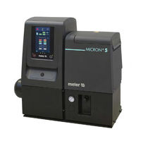
Meler Micron 5 Instruction Manual (118 pages)
Adhesive melter
Brand:
Meler
| Category:
Industrial Equipment
| Size: 13 MB
Table of Contents
Table of Contents
3
1 Safety Guidelines
11
General
11
Symbols
11
Mechanical Components
12
Electrical Components
12
Hydraulic Components
12
Pneumatic Components
12
Thermal Components
13
Materials
13
Noise Emission Declaration
13
Intended Use
14
Limited Use
14
2 Introduction
15
Description
15
Modes of Operation
16
Hot-Melt Melter Identification
16
Main Components
17
Main Components Micron Gear with Two Motor-Pumps
18
Control Card Components
19
Pumping Control Card Components
20
Micron Gear Series Range
21
Micron Gear Range Option Accessories
21
Automatic Feeder Option
21
Gas Injection Option
22
Air Dryer System
22
Bypass Valve Pressure Control System
22
Level Control System
22
Warning Light Option
22
Optional Equipment
22
3 Installation
23
Introduction
23
Installation Requirements
23
Free Space
23
Electrical Consumption
24
Compressed Air
25
Other Factors
25
Unpacking
25
Contents
25
Mounting the Equipment
26
Electrical Power Connection
26
Pneumatic Connection
27
Hose and Applicator Connection
28
Parameter Programming
28
Programming Working Temperatures
29
Selecting the Overheating Value
29
Keeping a Component on Display
30
External I/O Connections
30
Temperature Ok
31
External Standby
32
Low Level (Optional)
32
Output Disabled
33
Starting up the Motor (Ok Ext)
34
Motor Speed Set Point Reference (Ref Ext)
34
Failures Output in Pump Control Card
35
4 Melter Operation
37
General Information
37
Filling the Tank
38
Starting up the Melter Equipment
38
Melter Equipment Displays
39
Displaying the Temperature for each Component
40
Alarm Displays
41
Hot-Melt Level Display (Optional)
43
Display and Adjustment of the Working Speed
43
Temperature Adjustment
44
Programming the Applicator Parameters
45
Programming Process
45
Timer to Switch between on - Standby - off Modes
49
Password to Access Parameter Programming
50
Total Equipment Service Hours Counter
50
Counter that Warns of the Need to Change the Adhesive Agent Filter
51
Setting the Clock
52
Programming the Current Day and Hour
52
Programming Equipment Activation/Deactivation
53
Disabling the Equipment Activation/Deactivation Program
54
Programming the Equipment's Standby Function Activation/Deactivation
54
Disabling the Equipment Standby Function Programming
55
Special Function Buttons
56
Pumping Control
57
Starting up the Pump Control Card
57
Pumping Safety Measures
57
Password Security
58
LED Indicators
59
Modes of Operation
60
Mode of Operation with Internal Pumping Control and Internal Speed Control
60
Mode of Operation with Internal Pumping Control and External Speed Control
61
Mode of Operation with External Pumping Control and Internal Speed Control
62
Mode of Operation with External Pumping Control and External Speed Control
63
User Configuration Menu
64
Displaying Alarms and Reset Function
65
Maximum Rpm Alarm
65
Minimum Rpm Alarm
65
Variator Alarm
65
Configuring Speed Ramp
66
Programming Speed Ramp
67
Current Vin Voltage Display
68
By-Pass Valve Regulation
68
Manual Valve Control
68
Pneumatic Valve Control
68
Using the Air Drying System (Optional)
69
Turning off the Melter Equipment
69
5 Maintenance
71
Equipment Cleaning
71
System Depressurisation
73
Access to the Interior of the Equipment
73
Access to Distributor
73
Access to Pump Gear- Motor
73
Filter Maintenance
74
Cleaning the Tank
75
Changing Adhesive Type
75
Cleaning Burnt Adhesive
75
Emptying the Tank
76
Pump Maintenance
77
Inspecting for Leaks
77
Gear Motor Maintenance
77
Cleaning the Motor Fan
77
Checking the Lubricant
77
Recommended Lubricants
78
Safety Thermostat
78
Air Dryer Filter Maintenance
78
Remove the Equipment from Its Base
79
6 Troubleshooting
81
Melter
82
The Unit Does Not Turn on (5, 10 and 20 Adhesive Melters)
82
The Unit Does Not Turn on (35 Adhesive Melter)
82
Equipment Shortcircuit Malfunction
83
Tank
83
The Tank Does Not Heat (5, 10 and 20 Adhesive Melters)
83
The Tank Does Not Heat (35 Adhesive Melter)
83
The Tank Does Not Stop Heating (5, 10 and 20 Adhesive Melters)
84
The Tank Does Not Stop Heating (35 Adhesive Melter)
84
Temperature Fluctuations in the Tank
84
Manifold
85
The Manifold Does Not Heat (Micron, 1 Geared Motor)
85
The Manifold Does Not Heat (Micron, 2 Geared Motors)
85
The Manifold Does Not Stop Heating (Micron, 1 Geared Motor)
85
The Manifold Does Not Stop Heating (Micron, 2 Geared Motores)
86
Temperature Fluctuations in the Manifold/ Manifolds
86
Melter Does Not Pump
86
Problems Associated with Temperatures
86
The Pump Control Board Has Been Switched off
86
Check that the Machine Is Working in the Correct Operating Mode
87
Level Sensor
88
The Unit Does Not Indicate the Absence of Adhesive
88
Dry Air System
88
No Dry Air Is Fed to the Tank
88
Hose
89
Hose Does Not Heat
89
Hose Does Not Stop Heating
89
Temperature Fluctuations in Hose
89
Applicator
90
Applicator Does Not Heat
90
Applicator Does Not Stop Heating
90
Temperature Fluctuations in Applicator
90
Lay out Power Board
92
Lay out Control Board
93
Lay out Pump Control Board
93
Lay out Sensor Board
93
7 Technical Characteristics
95
Generals
95
Dimensions
97
Micron Gear Range Option Accessories
99
Automatic Feeder System
99
Air Drying System for Reactives Adhesives
99
Pneumatic By-Pass Valve Pressure Control System
99
Level Control System
99
Warning Light Option
99
Optional Equipment
100
Wheel System
100
Advertisement
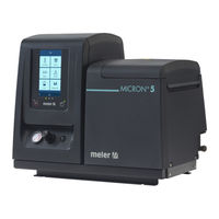
Meler Micron 5 Instruction Manual (108 pages)
Adhesive Melter
Brand:
Meler
| Category:
Industrial Equipment
| Size: 4 MB
Table of Contents
Table of Contents
3
1 Safety Guidelines
9
General
9
Symbols
9
Mechanical Components
10
Electrical Components
10
Hydraulic Components
10
Pneumatic Components
10
Thermal Components
11
Materials
11
Noise Emission Declaration
11
Intended Use
12
Limited Use
12
2 Introduction
13
Description
13
Modes of Operation
14
Hot-Melt Melter/Applicator Identification
14
Main Components
15
Main Components de MICRON + Gear with Two Motor-Pumps
16
Control Panel Components
17
Automatic Feeder Main Components (Optional)
18
General
18
MICRON + Series Range
19
Micron+ Gear Range Option Accessories
20
Automatic Feeder Option
20
Gas Injection Option
20
Air Dryer System
20
Bypass Valve Pressure Control System
20
Level Control System
20
Warning Light Option
20
Optional Equipment
20
3 Installation
21
Introduction
21
Installation Requirements
21
Electrical Consumption
22
Compressed Air
22
Other Factors
23
Unpacking
23
Contents
23
Mounting the Equipment
23
Electrical Power Connection
24
Pneumatic Connection
25
Hose and Applicator Connection
26
Parameter Programming
26
External I/O Connections
27
Connecting External Inputs and Outputs
29
Connecting Zone Inhibition
30
External Signals of Pumping Control
31
Connection of Externar Singnals for Pumping Control
31
Automatic Feeder Assembly
32
Pneumatic Connection
32
Suction Tube Connection
32
Placing the Suction Tube
32
Electrical Connections
33
4 Melter Operation
35
General Information
35
Filling the Tank
36
Starting up the Melter Equipment
36
Manual Pumping Permmision
37
Melter Equipment Display
38
General Characteristics
39
Navigation Icons
39
Save Changes
39
Interpretación de las Pantallas
39
Home Display
40
General Temperature Status
40
Alarms Status
41
Calendar Status
41
Adhesive Level Status
41
Pumping Status
42
Temperature Status
42
Temperature and Heating Shortcut Displays
43
Programming of Temperatures
44
Programming of Statuses
44
Menú Calendars
44
Units and Lenguage Menu
45
Date and Time Configuration
45
Alarms and Warnings
45
Pumping Control Menu
46
Modes of Operation
47
Pumping Safety' Function Activated
47
Pumping Safety' Function Deactivated
47
Operating Mode with Internal Pumping Control and Internal Speed Control
48
Operating Mode with Internal Pumping Control and External Speed Control
49
Operating Mode with External Pumping Control and Internal Speed Control
50
Operating Mode with External Pumping Control and External Speed Control
51
Configuring Speed Ramp
52
Main Menu
52
Heating' Menu
53
Heating Zones
53
Sequential Heating
54
Inhibitions
54
Auto Standby - off
55
Extra Temperature Settings
56
General Settings' Menu
57
Password Management
57
Extra Settings
58
Configuration of Input and Output Signals
59
Restore Default Values
59
Load' Menu
60
Screen 1: Minimum Adhesive Level Sensor
60
Screen 2: Automatic Adhesive Feeder
60
Screen 3: Dry Air/Gas Injection
60
Screen 4: Pressurisation (Only for Units with an Airtight Tank Lid)
61
Statistics' Menu
61
Menu '5. Pumping
62
Standby Function
63
By-Pass Valve Regulation
64
Manual Valve Control
64
Adjust Pneumatic Valve Control(DP1 / DP2) (Optional)
65
Using the Air Drying System (Optional)
65
Turning off the Melter Equipment
65
Use of the Automatic Feeder
66
Start up and Automatic Process
66
Sensitivity Adjustment
67
Positioning of the Level Sensor
67
Application for PC
68
5 Maintenance
69
Equipment Cleaning
69
System Depressurisation
71
Access to the Interior of the Equipment
71
Access to Distributor
71
Access to Pump Gear- Motor
71
Filter Maintenance
72
Cleaning the Tank
73
Changing Adhesive Type
73
Cleaning Burnt Adhesive
73
Emptying the Tank
74
Pump Maintenance
75
Inspecting for Leaks
75
Gear Motor Maintenance
75
Cleaning the Motor Fan
75
Checking the Lubricant
75
Recommended Lubricants
76
Safety Thermostat
76
Air Dryer Filter Maintenance
76
Remove the Equipment from Its Base
77
Automatic Feeder Maintenance
78
Cleaning of the Unit
78
Pneumatic System
78
Control of the Load Sensor
79
Inspection of the Aspiration Tube
79
Filter Maintenance
79
Control of Pneumatic Vibrator
79
6 Technical Characteristics
81
Generals
81
Dimensions
83
Micron+ Gear Range Option Accessories
85
Automatic Feeder System
85
Air Drying System for Reactives Adhesives
85
Pneumatic By-Pass Valve Pressure Control System
85
Level Control System
85
Warning Light Option
85
Optional Equipment
86
Wheel System
86
7 Electrical Drawings
87
8 Pneumatic Diagram
89
Components List
89
Pneumatic By-Pass Valve Control System (Optional)
89
Air Drying System (Optional)
89
Double Pressure System (Opcional)
90
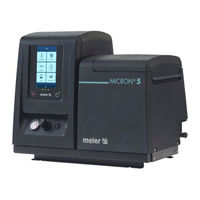
Meler Micron 5 Instruction Manual (120 pages)
Adhesive Melter
Brand:
Meler
| Category:
Melting Machines
| Size: 25 MB
Table of Contents
Table of Contents
3
1 Safety Guidelines
11
General
11
Symbols
11
Mechanical Components
12
Electrical Components
12
Hydraulic Components
12
Pneumatic Components
12
Thermal Components
13
Materials
13
Noise Emission Declaration
13
Intended Use
14
Limited Use
14
2 Introduction
15
Description
16
Modes of Operation
16
Hot-Melt Melter/Applicator Identification
16
Main Components
17
Control Panel Components
18
Automatic Feeder Main Components (Optional)
19
General
19
Notes
20
MICRON + Series Range
20
Incompatibilities
21
Automatic Feeder Option
21
Warning Light Option
21
VP Option
21
Optional Equipment
22
3 Installation
23
Introduction
23
Installation Requirements
23
Electrical Consumption
24
Compressed Air
24
Other Factors
25
Unpacking
25
Contents
25
Mounting the Equipment
25
Electrical Power Connection
26
Pneumatic Connection
27
Hose and Applicator Connection
28
Parameter Programming
28
External I/O Connections
28
Connecting External Inputs and Outputs
31
Interpretation of External Inputs and Outputs
32
Connecting Zone Inhibition
34
Connecting Product Passage Signal (Flowmeter)
35
Wireless Connection (Wi-Fi)
35
Automatic Feeder Assembly
36
Pneumatic Connection
36
Suction Tube Connection
36
Placing the Suction Tube
36
Electrical Connections
37
4 Melter Operation
39
General Information
39
Filling the Tank
39
Manual Starting up the Melter Equipment
40
Manual Pumping Permmision
41
Melter Equipment Display
42
Date and Time Menu
42
General Characteristics
43
Navigation Icons
43
Save Changes
43
Explanation of the Screen Contents
43
Home Display
44
General Temperature Status
44
Alarms Status
45
Calendar Status
45
Adhesive Level Status
45
Pumping Status
46
Temperature Status
46
Temperature and Heating Shortcut Displays
47
Programming of Temperatures
48
Programming of Statuses
48
Calendar
48
Units and Lenguage Menu
49
Date and Time Configuration
49
Alarms and Warnings
50
Main Menu
50
Heating' Menu
51
Heating Zones
51
Sequential Heating
52
Inhibitions
52
Auto Standby - off
53
Heating Extra Settings
54
Extra Settings' Menu
55
Password Management
55
Extra Settings
56
Configuration of Input and Output Signals
57
Restore Default Values
57
Statistics' Menu
58
Load' Menu
58
Screen 1: Minimum Adhesive Level Sensor
58
Screen 2: Automatic Adhesive Feeder
58
Automatic Pumping Block Function
59
Automatic Pumping Block' Enabled
59
Automatic Pumping Block' Disabled
60
Off after Reset' Function
61
Off after Reset' Enabled
61
Off after Reset' Disabled
62
Configuration of Turning on and Activating Pumping
62
Wireless Communication (Wi-Fi)
64
Connection Configuration
64
Flowmeter
65
System Calibration
65
Calculating the Adhesive Density
66
Product Configuration
66
Product Selection
68
Flowmeter Statistics
69
Standby Function
70
Turning off the Melter Equipment
70
Use of the Automatic Feeder
71
Start up and Automatic Process
71
Sensitivity Adjustment
72
Positioning of the Level Sensor
72
Application for PC
73
5 Maintenance
75
Equipment Cleaning
75
System Depressurisation
76
Access to Pneumatic Unit
77
Maintenance of the Filters
77
Changing the Pump Filter
77
Changing the Inlet Filter
78
Cleaning the Tank
79
Changing Adhesive Type
79
Cleaning Burnt Adhesive
79
Emptying the Tank
80
Safety Thermostat
81
Remove the Equipment from Its Base
81
Automatic Feeder Maintenance
82
Cleaning of the Unit
82
Pneumatic System
82
Control of the Load Sensor
83
Inspection of the Aspiration Tube
83
Filter Maintenance
83
Control of Pneumatic Vibrator
83
6 Technical Characteristics
85
Generals
85
Dimensions
87
Accessories
89
Low Level Detection System
89
Caster System
89
Adaptation Plate for Previous Models
89
7 Electrical Drawings
91
8 Pneumatic Diagram
93
Components List
93
CM /Stroke Pump
93
Advertisement
Meler Micron 5 Instruction Manual (98 pages)
Adhesive Melter
Brand:
Meler
| Category:
Melting Machines
| Size: 4 MB
Table of Contents
Table of Contents
3
1 Safety Guidelines
9
General
9
Symbols
9
Mechanical Components
10
Electrical Components
10
Hydraulic Components
10
Pneumatic Components
10
Thermal Components
11
Materials
11
Noise Emission Declaration
11
Intended Use
12
Limited Use
12
2 Introduction
13
Description
14
Modes of Operation
14
Hot-Melt Melter/Applicator Identification
14
Main Components
15
Control Panel Components
16
Automatic Feeder Main Components (Optional)
17
General
17
MICRON + Series Range
18
MICRON + Range Option Accessories
19
3X400 W/O Neutral Power Supply Voltage Option
19
Automatic Feeder Option
19
Warning Light Option
19
VP Option
19
Optional Equipment
19
3 Installation
21
Introduction
21
Installation Requirements
21
Electrical Consumption
22
Compressed Air
22
Other Factors
23
Unpacking
23
Contents
23
Mounting the Equipment
23
Electrical Power Connection
24
Pneumatic Connection
25
Hose and Applicator Connection
26
Parameter Programming
26
External I/O Connections
27
Connecting External Inputs and Outputs
29
Connecting Zone Inhibition
30
Automatic Feeder Assembly
31
Pneumatic Connection
31
Suction Tube Connection
31
Placing the Suction Tube
31
Electrical Connections
32
4 Melter Operation
33
General Information
33
Filling the Tank
34
Starting up the Melter Equipment
34
Manual Pumping Permmision
35
Melter Equipment Display
36
Date and Time Menu
36
General Characteristics
37
Navigation Icons
37
Save Changes
37
Interpretación de las Pantallas
37
Home Display
38
General Temperature Status
38
Alarms Status
39
Calendar Status
39
Adhesive Level Status
39
Pumping Status
40
Temperature Status
40
Temperature and Heating Shortcut Displays
41
Programming of Temperatures
42
Programming of Statuses
42
Menú Calendars
42
Units and Lenguage Menu
43
Date and Time Configuration
43
Alarms and Warnings
44
Main Menu
44
Heating' Menu
45
Heating Zones
45
Sequential Heating
46
Inhibitions
46
Auto Standby - off
47
Extra Temperature Settings
48
General Settings' Menu
49
Password Management
49
Extra Settings
50
Modbus Communications
50
Configuration of Input and Output Signals
51
Restore Default Values
51
Load' Menu
52
Screen 1: Minimum Adhesive Level Sensor
52
Screen 2: Automatic Adhesive Feeder
52
Statistics' Menu
52
Standby Function
53
Turning off the Melter Equipment
53
Use of the Automatic Feeder
54
Start up and Automatic Process
54
Sensitivity Adjustment
55
Positioning of the Level Sensor
55
Application for PC
56
5 Maintenance
57
Equipment Cleaning
57
System Depressurisation
58
Access to Pneumatic Unit
59
Filter Maintenance
59
Cleaning the Tank
60
Changing Adhesive Type
60
Cleaning Burnt Adhesive
61
Emptying the Tank
61
Safety Thermostat
62
Remove the Equipment from Its Base
62
Automatic Feeder Maintenance
63
Cleaning of the Unit
63
Pneumatic System
63
Control of the Load Sensor
64
Inspection of the Aspiration Tube
64
Filter Maintenance
64
Control of Pneumatic Vibrator
64
6 Technical Characteristics
65
Generals
65
Dimensions
67
Accessories
69
Low Level Detection System
69
Caster System
69
Adaptation Plate for Previous Models
69
7 Electrical Drawings
71
8 Pneumatic Diagram
73
Components List
73
CM /Stroke Pump
73
Meler Micron 5 Instruction Manual (98 pages)
Micron Piston Series
Brand:
Meler
| Category:
Melting Machines
| Size: 15 MB
Table of Contents
Table of Contents
3
1 Safety Guidelines
9
General
9
Symbols
9
Mechanical Components
10
Electrical Components
10
Hydraulic Components
10
Pneumatic Components
10
Thermal Components
11
Materials
11
Noise Emission Declaration
11
Intended Use
12
Limited Use
12
2 Introduction
13
Description
14
Modes of Operation
14
Hot-Melt Melter/Applicator Identification
14
Main Components
15
Control Card Components
16
MICRON Series Range
17
MICRON Range Option Accessories
18
400N or 400 Power Supply Voltage Option
18
Automatic Feeder Option
18
Warning Light Option
18
VP Option
18
Optional Equipment
18
3 Installation
19
Introduction
19
Installation Requirements
19
Electrical Consumption
20
Compressed Air
20
Other Factors
21
Unpacking
21
Contents
21
Mounting the Equipment
21
Electrical Power Connection
22
Pneumatic Connection
23
Hose and Applicator Connection
24
Parameter Programming
24
Programming Working Temperatures
24
Selecting the Overheating Value
25
Keeping a Component on Display
26
External I/O Connections
26
Temperature Ok
26
External Standby
27
Low Level (Optional)
28
Output Disabled
28
4 Melter Operation
31
General Information
31
Filling the Tank
32
Starting up the Melter/Applicator Equipment
32
Melter/Applicator Equipment Displays
33
Displaying the Temperature for each Component
34
Alarm Displays
34
Hot-Melt Display Level (Optional)
35
Operational Pressure Display and Adjustment
36
Temperature Adjustment
36
Programming the Applicator Parameters
37
Programming Process
37
Timer to Switch between on - Standby - off Modes
41
Password to Access Parameter Programming
42
Total Equipment Service Hours Counter
42
Counter that Warns of the Need to Change the Adhesive Agent Filter
43
Setting the Clock
44
Programming the Current Day and Hour
44
Programming Equipment Activation/Deactivation
45
Disabling the Equipment Activation/Deactivation Program
46
Programming the Equipment's Standby Function Activation/Deactivation
46
Disabling the Equipment Standby Function Programming
47
Special Function Buttons
48
Turning off the Melter/Applicator Equipment
49
5 Maintenance
51
Equipment Cleaning
51
System Depressurisation
52
Access to Pneumatic Unit
53
Filter Maintenance
53
Cleaning the Tank
54
Changing Adhesive Type
54
Cleaning Burnt Adhesive
55
Emptying the Tank
55
Safety Thermostat
56
Remove the Equipment from Its Base
56
6 Troubleshooting
57
Melter
58
The Unit Does Not Turn on
58
Equipment Shortcircuit Malfunction
58
Tank
58
The Tank Does Not Heat
58
The Tank Does Not Stop Heating
59
Temperature Fluctuations in the Tank
59
Manifold
60
The Manifold Does Not Heat
60
The Manifold Does Not Stop Heating
60
Temperature Fluctuations in the Manifold
60
Pump
61
The Shaft Is Not Moving (the Pressure Gauge Shows no Pressure Reading)
61
The Shaft Is Not Moving (the Pressure Gauge Shows Pressure Readings)
61
Inefficient Pumping Process
61
Adhesive Leaks
62
Hose
62
Hose Does Not Heat
62
Hose Does Not Stop Heating
62
Temperature Fluctuations in Hose
63
Applicator
63
Applicator Does Not Heat
63
Applicator Does Not Stop Heating
63
Temperature Fluctuations in Applicator
64
Lay out Power Board
65
Lay out Control Board
66
7 Technical Characteristics
67
Generals
67
Dimensions
69
Accessories
71
Low Level Detection System
71
Wheel System
71
Adaptation Plate for Previous Models
71
8 Electrical Drawings
73
9 Pneumatic Diagram
75
Components List
75
CM /Stroke Pump
75
Meler Micron 5 Instruction Manual (42 pages)
ADHESIVE AUTOMATIC FEEDER
Brand:
Meler
| Category:
Laboratory Equipment
| Size: 7 MB
Table of Contents
Table of Contents
3
1 Safety Guidelines
7
General
7
Symbols
7
Mechanical Components
8
Electrical Components
8
Hydraulic Components
8
Pneumatic Components
8
Thermal Components
9
Materials
9
Noise Emission Declaration
9
Intended Use
10
Limited Use
10
2 Introduction
11
Description
11
Operation Modes
12
Identification of the Hot Melt System
12
Main Components
13
General
13
Kg Container
14
Kg Container Settings
15
3 Installation
17
Preliminaries
17
Installation Requirements
17
Electrical Consumption
18
Compressed Air
18
Unpacking
18
Content
18
Feeder Assembly
19
Pneumatic Connection
19
Suction Tube Connection
20
Connecting Control Detectors
20
Installation of External Control Box
20
Connection of Signals for Standby Function
21
Pellet Container Installation
21
Electrical Power Supply Connections
21
Container with Reset Button
21
Container with Pellet Level Control
22
Placing the Suction Tube
22
4 Use of the Unit
23
Start up and Automatic Process
23
Sensor Adjustments
24
Sensitivity Adjustment
24
Positioning of the Level Sensor
24
Level Stabilisation Time
25
Programmable Times Using the Timer
25
Disconnection Delay Time
25
Operating Alarms
25
Change to Standby Time
26
Setting Programmable Times Using the Timer
26
Manual Feeding
27
Pellet Container Level Sensor
27
5 Maintenance
29
Cleaning of the Unit
29
Pneumatic System
29
Control of the Load Sensor
30
Inspection of the Aspiration Tube
30
Filter Maintenance
30
Control of Pneumatic Vibrator
30
6 Technical Characteristics
31
General
31
7 Electrical Drawings
33
Meler Micron 5 Instruction Manual (30 pages)
Annex communications ModBus/ProfiBus/Ethernet IP/ProfiNet
Brand:
Meler
| Category:
Network Hardware
| Size: 3 MB
Table of Contents
Table of Contents
3
1 Safety Guidelines
5
General
5
Symbols
5
Mechanical Components
6
Electrical Components
6
Hydraulic Components
6
Pneumatic Components
6
Thermal Components
7
Materials
7
Noise Emission Declaration
7
Intended Use
8
Limited Use
8
2 Modbus
9
Main Components
9
Enable Modbus Communications
10
Communication Protocols
10
Connections
10
3 Ethernet Ip
11
Main Components
11
Connecting the Communications Cable
12
Enable Modbus Communications
13
Communication Protocols
13
Connections
13
IP Address Setting
14
PLC Configuration. EDS File
14
4 Profinet
15
Main Components
15
Connecting the Communications Cable
16
Enable Modbus Communications
17
Communication Protocols
17
Connections
17
Node Name Configuration
18
PLC Configuration. GSDML File
18
5 Profibus
19
Main Components
19
Connecting the Communications Cable
20
Enable Modbus Communications
21
Communication Protocols
21
Connections
22
Node Address Configuration
22
PLC Configuration. GSD File
22
6 Communication Data Table
23
7 Spare Parts List
27
Communications Gateway
29
Meler Micron 5 Instruction Manual (28 pages)
Appendix external display
Brand:
Meler
| Category:
Laboratory Equipment
| Size: 4 MB
Table of Contents
Table of Contents
3
1 Safety Guidelines
5
General
5
Symbols
5
Mechanical Components
6
Electrical Components
6
Hydraulic Components
6
Pneumatic Components
6
Thermal Components
7
Materials
7
Noise Emission Declaration
7
Intended Use
8
Limited Use
8
2 Introducction
9
Description
10
Modes of Operation
10
Hot-Melt Melter/Applicator Identification
10
Main Components of the Equipment
11
Control Panel Components
12
Optional Equipment
13
Controller Bracket
13
3 Installation
15
Introduction
15
Installation Requirements
15
Electrical Consumption
16
Compressed Air
16
Mounting the Equipment
16
Other Factors
17
Unpacking
17
Contents
17
Electrical Power Connection
18
Connection of the External Display to the Melter
18
Parameter Programming
19
Pneumatic Connection
19
4 Technical Characteristics
21
Dimensions
21
5 Electrical Drawings
23
6 Spare Parts List
25
Electronic Assembly
26
Ec Declaration of Conformity
27
Meler Micron 5 Quick Start Manual (2 pages)
Micron series
Brand:
Meler
| Category:
Water Pump
| Size: 4 MB
Table of Contents
Components, Options and Accessories
1
Mounting the Equipment
1
Dimensions/ Free Space
1
Electrical Power Connection
1
Pneumatic and Hose Connection
1
External I/O Connections (Optional)
2
Maximum Charge of Adhesive
2
Starting up the Melter Equipment
2
Control Board
2
Temperature Adjustment
2
Selecting the Overheating and Standby Values
2
Pump Control Card
2
Speed Working Adjustment
2
Meler Micron 5 Quick Start Manual (2 pages)
MICRON PUMP SERIES
Brand:
Meler
| Category:
Water Pump
| Size: 3 MB
Table of Contents
Components and Accessories
1
Dimensions/Free Space
1
Mounting the Equipment
1
Electrical Power Connection
1
Pneumatic and Hose Connection
2
Maximum Charge of Adhesive
2
Control Board
2
Starting up the Melter Equipment
2
Temperature Adjustment
2
Selecting the Overheating Value/ Standby
2
External I/O Connections (Optional)
2
Advertisement
Related Products
Meler Micron + Piston Series
Meler Micron + 10
Meler Micron + 20
Meler MICRON 5 TPD
Meler micron 35
Meler Micron PUR LC
Meler Micron PUR MC
Meler Micron Mod
Meler MICRON+ GEAR Series
Meler Micron Gear Series
Meler Categories
Industrial Equipment
Melting Machines
Laboratory Equipment
Water Pump
Controller
More Meler Manuals
Login
Sign In
OR
Sign in with Facebook
Sign in with Google
Upload manual
Upload from disk
Upload from URL