
Related Manuals for Panasonic CF-WEB194AC


Summary of Contents for Panasonic CF-WEB194AC
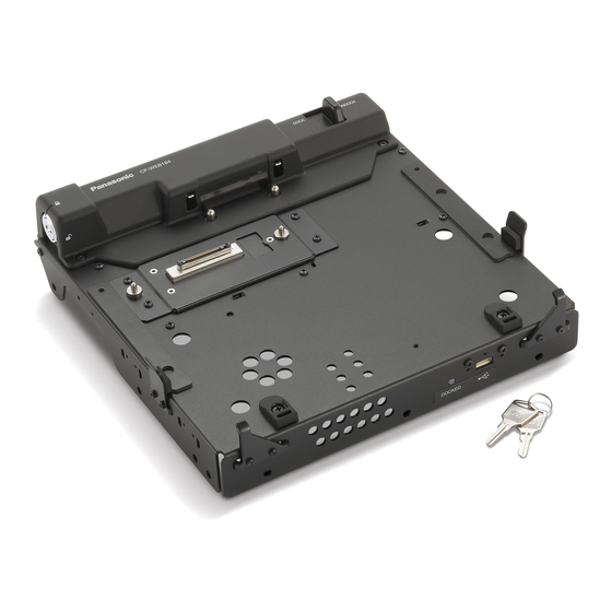
- Page 1 ORDER NO. CPD1008208CE Car Mounter CF-WEB194AC Model No. This is the Service Manual for worldwide. This is the Service Manual for worldwide. © Panasonic Corporation 2010. Unauthorized copying and distribution is a violation of law.
- Page 2 Precautions for Operating the Car Mounter If a Malfunction or Trouble Occurs, Avoid a Lot of Water, Moisture, Immediately Stop Use Steam, Dust, Oily Vapors, etc. Otherwise, possibly resulting in fire or If a Malfunction Occurs, Immediately electric shock. Unplug the Car Plug and Remove Use Only the Specified Car Adaptor the Computer From this product With This Product...
- Page 3 <For Europe> Declaration of Conformity (DoC) “Hereby, Panasonic declares that this Car Mounter is in compliance with the essential requirements and other relevant provisions of EU Council Directives.”...
- Page 4 Use of an interface cable longer than 3 m {9.84 feet} is not recommended. 11-E-1 Importer’s name & address pursuant to the EU GPSD (General Product Safety Directive) 2001/95/ EC Art.5 Panasonic Computer Products Europe, Panasonic Marketing Europe GmbH Hagenauer Straße 43 65203 Wiesbaden Germany...
-
Page 5: Table Of Contents
CONTENTS 1. Specifications ················································································································· 1-1 2. Names and Functions of Parts ······················································································· 2-1 3. Wiring Connection Diagram ··························································································· 3-1 4. Reassembly ···················································································································· 4-1 5. Exploded View ··············································································································· 5-1 6. Replacement Parts List ·································································································· 6-1... -
Page 6: Specifications
Specifications (Dimensional Drawing) Installation holes are provided in the areas indicated by the arrows in the figure above. -
Page 7: Names And Functions Of Parts
2. Names and Functions of Parts A. Security lock LOCK You can connect a Kensington cable. Refer to the instruction manual of the cable. B. LAN port C. USB port D. Serial port E. External display port F. Headphone jack G. -
Page 8: Wiring Connection Diagram
3. Wiring Connection Diagram Headphone Display Microphone Output Serial 1 Serial 2 CN908 CN915 CN916 CN910 CN909 CN913 CN912 CN911 CN917 Main PCB CN905 CN914 CN906 CN902 CN920 Expansion Bus (CN901) CN919 CN903 Docking PCB Front PCB Connector by Cable Direct connection by Connectors Parts on Bottom Side... -
Page 9: Reassembly
4 Reassembly 4.1. Reassembly Instructions 4.1.1. Preparation Before disassembling, be sure to make the following preparations • Disconnect the AC adaptor. • Remove other devices if they are connected. Attention: • You cannot reuse the Conductive Clothes and the heat dissipating parts such as Sheet and Rubber. Use new parts. 4.1.2. - Page 10 ■ Base Plate Ass’y preparation. *Notice CN Cover Screw Sheet 1. Remove the Release Paper of CN Cover Screw Sheet and attach it to Base Plate Ass'y. When attaching, make sure CN Cover Screw Sheet does not run over the bar ring of Base Plate Ass'y. Set A in the B direction.
- Page 11 *Notice 1. Apply SANKOL CFD-409 to the 4 operating parts of Base Plate Ass'y. Check the wet condition of SANKOL CFD-409. Permeation to parts other than the coating side is acceptable. SANKOL CFD-409 SANKOL CFD-409 Base Plate Ass'y SANKOL CFD-409 Base Plate Ass'y Base Plate Ass'y SANKOL CFD-409...
- Page 12 *Notice 1. Remove the Wave Washer and Nut B from the Lock Unit Ass'y Lock Unit Ass'y, set the Key Cam Plate, fix the Wave Washer and Nut B<K61> again. Key Lock Cover Use the special jig. Screw<N2> 2. Set the Nut B<K61> to the Key Cam Plate and Key Cam Plate tighten with the Key Lock Cover.
- Page 13 4.1.3. Attaching the Back Cover 1. Attach the Back Cover to the Back Plate Ass'y and fix with 2 Screws <N2>. No.1 to No.2. <N2> :No.2 Back Cover <N2> :No.1 Back Plate Ass'y Screws <N2>:DRSB3+6FKL ■ Back Cover preparation. *Notice 1.
- Page 14 ■ Attaching the Back Cover Ass’y. *Notice 1. Attach Back Cover to Base Plate Ass'y and tighten with Screws<N2>. Screw<N2> Use the special jig. Tightening order of Screws<N2>: a - b Back Cover Ass'y Base Plate Ass'y Torque of tightening screw : Screws<N2>...
- Page 15 4.1.4. Attaching the Main PCB and assembling the IO Cas'y Ass'y 1. Attach the DC IN CN Cover to the IO Case and fix with 1 Screw <N2>. No.1. 2. Attach the PCB Sheet to the Main PCB, set it in the IO Case and fix with 6 Screws <N5>. No.2 to No.7. 3.
- Page 16 ■ Attaching the Main PCB. *Notice 1. Attach Main PCB to IO Case Ass'y. Main PCB 2. Tighten IO Case Ass'y and Main PCB with Screws <N5>. Use the special jig Screw <N5> Screw <N5> Screw Screw <N5> <N5> Screw <N5>...
- Page 17 4.1.5. Attaching the IO Case Ass'y 1. Attach the IO Case Ass'y to the Base Plate Ass'y and fix with 5 Screws <N2>. No.1 to No.5. <N2> <N2> :No.2 :No.1 <N2> :No.5 <N2> :No.4 <N2> :No.3 Base Plate Ass'y IO Case Ass'y Screws <N2>:DRSB3+6FKL ■...
- Page 18 *Notice 1. After finishing Cable Cover Ass'y assembly operation, hold both sides so that Base Plate Ass'y and IO Case Ass'y do not come off, and then rotate the product in front and back direction Screw (See the illustration on the left). <N2>...
- Page 19 4.1.6. Attaching the Front PCB 1. Connect the Cable to the Front PCB Connecter (CN919) and fix to the Base Plate Ass'y with 2 Screws <N2>. No.1 to No.2. 2. Fix the Cable Cover with 3 Screws <N2>. No.3 to No.5. <N2>...
- Page 20 4.1.7. Assembling and attaching the Docking PCB Ass'y 1. Connect 2 FFC DU CN to the Connecter (CN902,CN903) and attach the Cable and the I/O Antenna Plate 2 to the DU Angle Ass'y. 2. Attach the DU CN Gasket and the Dockleg Cover Sheet to the IO Dock Leg. 3.
- Page 21 ■ DU CON Cover preparation *Notice Attaching standard of FFC Protect Sheet 1. Remove the Release Paper of DU CON Cover Spacer Tolerance of misalignment between DU Leg Plate and attach it to DU CON Cover. and FFC Protect Sheet: 2 ± 1 mm 2 mm protruded.
- Page 22 *Notice 1. Tighten Docking PCB Ass'y and DU Leg Plate Ass'y to DU CON Cover Ass'y with Screws <N2>. make sure the direction is correct. DU CON Cover Ass'y Use the special jig. Docking PCB Ass'y DU Leg Plate Ass'y Torque of tightening screw : Screw<N2>...
- Page 23 4.1.8. Attaching the Unit Guide, Cable Hold Plate, Side Guide Plate and Unit Guide Plate 1. Attach the Unit Guide to the Base Plate Ass'y and fix with 2 Screws <N6>. 2. Attach the Cable Hold Plate and fix with 3 Screws <N2>. No.1 to No.3. Unit Guide <N6>...
- Page 24 ■ Attaching the Cable Hold Plate. *Notice 1. Attach Cable Hold Plate to Base Plate Ass'y and tighten with Screws<N2>. Base Plate Ass'y Tightening order of Screws<N2>: a - b - c Screw<N2> Cable Hold Plate Torque of tightening screw : Screw<N2>...
- Page 25 ■ How to paste labels, cushions, etc. S1:Insulation S2:Pinching Cables Serial Label CAUTION S3:Sharp Edge S4:Check Parts NO. S5:Others *Notice 1. Attach Name Plate to Base Plate Ass'y. Base Plate Ass'y Attaching precision: 0 ± 0.5 mm to each marking line. 2.
-
Page 26: Exploded View
(10 ± 2 kgf.cm) 0.45 ± 0.05 N.m E 1.4 N ± 0.1 N.m (4.5 ± 0.5 kgf.cm) (14 ± 1 kgf.cm) C 0.8 ± 0.08 N.m F 0.5 N ± 0.05 N.m (8.0 ± 0.8 kgf.cm) (5 ± 0.5 kgf.cm) CF-WEB194AC... -
Page 27: Replacement Parts List
6. Replacement Parts List Note : Important Safety Notice Components identified by mark have special characteristics important for safety. When replacing any of these components, use only manufacturer's specified parts. CF-WEB194AC REF. NO and AREA PART NO. DESCRIPTION Q'TY Main Block Unit... - Page 28 DFMD1209ZA DU SPACER LEFT DFMD1210ZA DU SPACER RIGHT DFMD7B41ZA KEY STOPPER DFMD7B42ZA KEY CAM PLATE DFSK008YA LOCK UNIT XNH19GFJ M19 NUT DFMD7A19ZA I/O ANTENNA PLATE 2 DRHM0068ZA TORX SCREW DRSB3+6FKL SCREW DXSN2+8FNL SCREW DXYN3+J7FNL SCREW IKT0104AA SCREW DRHM0104ZAT SCREW DXYN26+J6FNL SCREW...
Need help?
Do you have a question about the CF-WEB194AC and is the answer not in the manual?
Questions and answers