DMP Electronics 9800 Series Installation And Programming Manual
Graphic touchscreen keypad
Hide thumbs
Also See for 9800 Series:
- Installation and programming manual (40 pages) ,
- Installation manual (25 pages) ,
- Quick start manual (2 pages)

Related Manuals for DMP Electronics 9800 Series


Summary of Contents for DMP Electronics 9800 Series
- Page 1 9800 Series Graphic Touchscreen Keypad INSTALLATION AND PROGRAMMING GUIDE System Armed Panic CURRENT Chime TODAY Reset ARMED Favorites WEDNESDAY...
-
Page 3: Table Of Contents
TABLE OF CONTENTS About the Keypad ........1 Test the Keypad ........26 Keypad Features .........2 Additional Programming ......27 Programmable Carousel Menu ....... 3 End User Training ........29 Enter Characters .........4 Arm and Disarm the System ......30 Replace the Keypad Battery ......31 Select a Location ........6 Icon Reference ............32 Install the Keypad ........7... -
Page 5: About The Keypad
ABOUT THE KEYPAD 9800 Series Wireless Graphic Touchscreen Keypads offer flexible features and functionality. Each keypad provides: • AC Power/Armed LED • Full color touchscreen display • Built-in proximity card reader • Internal speaker • Wireless communication • 12 VDC plug-in power supply (9862) and wire harness •... -
Page 6: Keypad Features
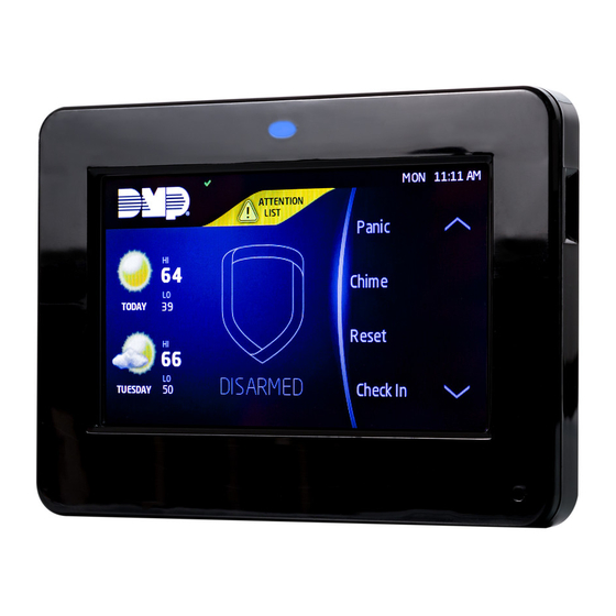
System Armed Press the Navigation Arrows Home screen Panic or touch and drag Shield the menu to scroll CURRENT Chime TODAY Reset Local Weather ARMED Favorites WEDNESDAY Figure 1: Keypad Features 9800 Series Installation and Programming Guide Digital Monitoring Products, Inc. -
Page 7: Programmable Carousel Menu
Display In Menu to select that option to display in the carousel menu. Press that box again to deselect that option. See Figure 2. Brightness Display In Menu Chime Tone Reset Check In Volume Easy Exit Figure 2: Keypad Options Digital Monitoring Products, Inc. 9800 Series Installation and Programming Guide... -
Page 8: Enter Characters
• Press abc to enter lowercase letters. • Press !@# to enter special characters. Press 123 to enter numbers and to return to the number pad. See Figure 4. • 9800 Series Installation and Programming Guide Digital Monitoring Products, Inc. - Page 9 Return to Home Screen Select Areas Special Characters ENTER CODE: Uppercase/ Lowercase Letters Number Pad Figure 3: Number Pad Figure 4: Standard Keyboard Digital Monitoring Products, Inc. 9800 Series Installation and Programming Guide...
-
Page 10: Select A Location
SELECT A LOCATION 9800 Series Wireless Graphic Touchscreen Keypads provide a built–in survey capability to allow one person to confirm keypad communication with the wireless receiver or panel. This allows you to determine the best location for the keypad. Press Options in the carousel menu. -
Page 11: Install The Keypad
Repeat with the other slot. Separate the cover from the base and set the cover containing the keypad components aside. See Figure 5. Figure 5: Separate the Keypad Housing Digital Monitoring Products, Inc. 9800 Series Installation and Programming Guide... -
Page 12: Install The 9862 Keypad
Plug in the power supply. Connect the other end of the power supply harness to the 4-pin power connector on the keypad without removing the PCB from the keypad housing, and snap the keypad into the base. 9800 Series Installation and Programming Guide Digital Monitoring Products, Inc. -
Page 13: Install The 9862Usb Keypad
Place the outlet screw through the hole in the plastic strap and secure it into the outlet. Plug the micro USB end of the cable into the back of the keypad. See Figure 9. Digital Monitoring Products, Inc. 9800 Series Installation and Programming Guide... - Page 14 Transformer and Strap Figure 7: Attach Legs Figure 8: Install Transformer Strap Micro Figure 9: Connect Power 9800 Series Installation and Programming Guide Digital Monitoring Products, Inc.
-
Page 15: Connect The Keypad
Reset the panel three times. The yellow LED at the top of the panel will begin flashing between each press. Wait for sixty seconds. When communication is confirmed, the LED will turn green and will stay on steady. Digital Monitoring Products, Inc. 9800 Series Installation and Programming Guide... - Page 16 Faulty: The keypad displays Pairing Failed, followed by the Reset screen. Reset your panel and press Pair to restart the pairing process. The panel will auto pair with wireless keypads until it pairs with four keypads or until ten minutes have passed. 9800 Series Installation and Programming Guide Digital Monitoring Products, Inc.
- Page 17 Set the keypad address at 1-16 for XR550 Series panels or 1-8 DEVICE NO: - for other compatible panels. Device Name DEVICE SETUP Press any select area, then enter a name for the wireless *UNUSED* keypad. Digital Monitoring Products, Inc. 9800 Series Installation and Programming Guide...
- Page 18 SUPRVSN TIME: 240 are 0, 60, or 240 minutes. Configure additional options as needed. To configure custom card options for the keypad, do not program CARD OPTIONS in Device Setup. 9800 Series Installation and Programming Guide Digital Monitoring Products, Inc.
-
Page 19: Program The Keypad
Use this option to enable or disable the panic keys. Press the icon name: PN (panic), EM (emergency), and FI (fire). Once the panic option is enabled, an asterisk displays next to the selected option(s). Digital Monitoring Products, Inc. 9800 Series Installation and Programming Guide... - Page 20 H/S/A system. Default is 2. Enable Tamper ENABLE TAMPER? If the keypad is mounted on a wall, select YES to enable the NO YES wall tamper. Default is NO. 9800 Series Installation and Programming Guide Digital Monitoring Products, Inc.
-
Page 21: Custom Card Format
ZN 3 REX TIME. No user code information is sent to the panel. The menu advances to NO COMM WITH PNL. The default card format is DMP. Digital Monitoring Products, Inc. 9800 Series Installation and Programming Guide... - Page 22 SINGLE CARD FORMAT and WIEGAND CODE LENGTH will default to 45. Format Name FORMAT NAME Press any select area to rename the card format. Press CMD *UNUSED* to save and advance. 9800 Series Installation and Programming Guide Digital Monitoring Products, Inc.
- Page 23 Position = 9 Received Received Length = 8 Length = 16 Position = 25 Position = 0 Example: Wiegand Code Length = 26 bits Figure 10: Wiegand Data Stream Bit Location Digital Monitoring Products, Inc. 9800 Series Installation and Programming Guide...
- Page 24 In addition to user code verification, door access is only granted when any one site code programmed at the SITE CODE ENTRY option matches the site code received in the Wiegand string. 9800 Series Installation and Programming Guide Digital Monitoring Products, Inc.
- Page 25 All bits are read and converted into a decimal number string. The number string is left padded with 0 (zero) if needed for long user code lengths. Example: # decoded 1234567 10 digits 0001234567 4 digits 4567 Digital Monitoring Products, Inc. 9800 Series Installation and Programming Guide...
- Page 26 Press the first select key or area to choose LAST (Keep Last NO COMM WITH PNL State). The relay remains in the same state and does not LAST change when communication is lost. 9800 Series Installation and Programming Guide Digital Monitoring Products, Inc.
- Page 27 While the info is being uploaded to the keypad, the keypad SURE? NO YES displays ADDING INFO. ADDING INFO COMPLETED displays to confirm a successful upload. Press and release the Micro SD card to eject. Digital Monitoring Products, Inc. 9800 Series Installation and Programming Guide...
-
Page 28: Carousel Z-Wave Items
Z-Wave to display the Edit Z-Wave icon for the Lights, Doors and Thermostats screens. Select Edit Favorites to display the Edit Z-Wave icon on Figure 12: Shortcut Items the Favorites screen. See Figure 12. 9800 Series Installation and Programming Guide Digital Monitoring Products, Inc. -
Page 29: Select Language
Default is English. Note: The keypad does not translate information from the panel that displays on the keypad screen. See Figure 13. Figure 13: Select Language Digital Monitoring Products, Inc. 9800 Series Installation and Programming Guide... -
Page 30: Test The Keypad
Exit the Installer Options Menu KPD KPD Press CMD until the display returns to the Installer Options OPT DIAG STOP screen. Select STOP to exit the Installer Options menu. 9800 Series Installation and Programming Guide Digital Monitoring Products, Inc. -
Page 31: Additional Programming
Press RESTART. Do not remove the Micro SD card or disrupt power. 10. When the keypad is finished restarting and returns to the home screen, remove the Micro SD card. Digital Monitoring Products, Inc. 9800 Series Installation and Programming Guide... -
Page 32: End User Training
Tap CMD to advance to MENU? NO YES. Tap YES. Enter your user code, then tap CMD. Tap CMD to advance through the menu items. To enter a menu, tap any select area. 9800 Series Installation and Programming Guide Digital Monitoring Products, Inc. -
Page 33: Arm And Disarm The System
If a selection is not made, all areas will automatically arm AWAY. If ENTER CODE: displays, enter a user code at the keypad or present a credential to the proximity reader. Digital Monitoring Products, Inc. 9800 Series Installation and Programming Guide... -
Page 34: Replace The Keypad Battery
Observe polarity and connect the battery lead connector to the keypad battery header. Place the new battery on the keypad PCB using double-sided sticky tape. See Figure 15. Battery Connection Battery Figure 15: Replace the Battery 9800 Series Installation and Programming Guide Digital Monitoring Products, Inc. -
Page 35: Icon Reference
Ready To Exit Exit Timer Popups Menu Enter Code Arm Instant Attention List Alert Home Installer Navigation Z-Wave Edit Arming Options Panic Options Home Sleep Away All System Emergency Perimeter Police Fire Digital Monitoring Products, Inc. 9800 Series Installation and Programming Guide... - Page 36 Z-Wave Thermostats Controls Decrease Increase Auto Heat Cool Room Temp Status Bar Header System Ready Attention List Armed (Area) Home Sleep Away Perimeter All System Chime Battery Trouble AC Trouble Wi-Fi 9800 Series Installation and Programming Guide Digital Monitoring Products, Inc.
-
Page 37: Public Card Formats
CODE LENGTH POSITION LENGTH POSITION LENGTH DIGITS H10301 26 BIT H10302 37 BIT W/O FAC H10304 37 BIT W/FAC FARPOINTE 39 BIT CORPORATE 1000 35 BIT CORPORATE 1000 48 BIT Digital Monitoring Products, Inc. 9800 Series Installation and Programming Guide... -
Page 38: Credentials
STANDARD LIGHT PROXIMITY CARD PSK-3 PROXIMITY KEY RING TAG PSM-2P ISO IMAGEABLE PROXIMITY CARD 1306 PROX PATCH™ 1326 PROXCARD II® CARD 1346 PROXKEY III® ACCESS DEVICE 1351 PROXPASS® 1386 ISOPROX II® CARD 9800 Series Installation and Programming Guide Digital Monitoring Products, Inc. -
Page 39: Ordering Information
Graphic Touchscreen Keypad (white, 4 zones, prox reader) 9862-USB-B Graphic Touchscreen Keypad with Micro USB (black, 4 zones, prox reader) 9862-USB-W Graphic Touchscreen Keypad with Micro USB (white, 4 zones, prox reader) Digital Monitoring Products, Inc. 9800 Series Installation and Programming Guide... - Page 40 Replacement Deskstand for 9800 Keypads (black, 10 pack) 9800-STAND-W/10 Replacement Deskstand for 9800 Keypads (white, 10 pack) Batteries 9800BAT2400/8 Replacement Battery for 9800 Keypads (3.8 V, 2400 mAh, 8 pack) 9800 Series Installation and Programming Guide Digital Monitoring Products, Inc.
-
Page 41: Compliance Specifications
Operating Voltage 12 VDC Standby Current 120 mA at 12 VDC Alarm Current 206 mA at 12 VDC Dimensions 5.8”W x 4.135”H x 0.6D Compatibility XTLplus/XTLtouch Series Panels XT30/XT50 Series Panels XR150/XR550 Series Panels Digital Monitoring Products, Inc. 9800 Series Installation and Programming Guide... -
Page 42: Certifications
CERTIFICATIONS FCC Part 15: CCKPC0132 Industry Canada: 5251A-PC0132 Intertek (ETL) Listed ANSI/UL 985 Household Fire Warning ANSI/UL 1023 Household Burglar ANSI/UL 1076 Proprietary Burglar ANSI/UL 1610 Central Station Burglar 9800 Series Installation and Programming Guide Digital Monitoring Products, Inc. -
Page 43: Fcc Information
• Connect the equipment into an outlet on a circuit different from that to which the receiver is connected. • Consult the dealer or an experienced radio/TV technician for help. Digital Monitoring Products, Inc. 9800 Series Installation and Programming Guide... -
Page 44: Industry Canada Information
Information furnished is believed to be accurate and reliable. This information is subject to change without notice. 9800 Series Installation and Programming Guide Digital Monitoring Products, Inc. - Page 48 LT-1367 20161 1.01 © 2020 Digital Monitoring Products, Inc.
Need help?
Do you have a question about the 9800 Series and is the answer not in the manual?
Questions and answers