Table of Contents
Advertisement
Quick Links
Advertisement
Table of Contents

Related Manuals for DMP Electronics 9863


Summary of Contents for DMP Electronics 9863
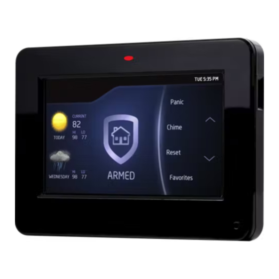
- Page 1 InstallatIon GuIde 9800 Series Wireless Graphic Touchscreen Keypads...
- Page 2 © 2014 Digital Monitoring Products, Inc. Information furnished by DMP is believed to be accurate and reliable. This information is subject to change without notice.
-
Page 3: Dmp Keypad Features
The Model 9862 keypad a built-in proximity card reader designed to read DMP/HID proximity credentials. The Model 9863 keypad provides a built-in proximity card reader designed to read DMP/HID proximity credentials. The Model 9863 keypad also provides a door strike relay and allows Wiegand input from external card readers. -
Page 4: Panic Icons
Select Areas Select Area 1 Select Area 2 Select Area 3 Select Area 4 There are four Select Areas in the display as seen in Figure 2. These Select Areas are one of the features that make the system so easy to operate. -
Page 5: Internal Speaker Operation
Internal Speaker Operation All keypads emit standard tones for screen presses, entry delay, and system alerts. The speaker also provides distinct burglary, fire, zone monitor, and prewarn cadences. The keypads provide an alternate prewarn with alarm cadence that occurs when the status list displays a zone alarm. -
Page 6: End-User Options
End-User Options All keypads provide three keypad adjustments the end-user can make through a User Options Menu. The user can also view the keypad model number and address. Scroll through the carousel menu and press the Options icon until it glows. The screen displays the available options shown below. -
Page 7: Keypad Serial Number
Keypad Serial Number For your convenience, an additional pre-printed serial number label is included. Prior to installing the device, record the serial number or place the pre-printed serial number label on the panel programming sheet. This number is required during programming. The keypads can be programmed into the control panel by entering the serial number in Device Setup panel programming, or alternatively using the wireless keypad association operation. -
Page 8: Mounting The Keypad
Mounting the Keypad Secure the keypad base to the wall ensuring that the wall tamper switch makes proper contact with the wall. Use the supplied screws in the mounting hole locations as shown in Figure 9. Keypad Back Surface and Backbox Mounting Holes Keypad Back External Card... -
Page 9: Standby Battery
Standby Battery The keypad rechargeable battery provides 24 hours of backup battery power when primary DC power is not available. It is shipped already installed inside the keypad. The battery is intended for backup power only and not to operate the keypad on a daily basis. -
Page 10: Programming The Keypad In The Panel
Programming the Keypad in the Panel The keypads can be programmed into the control panel by entering the serial number in Device Setup panel programming, or alternatively using the wireless keypad association operation. A maximum of 4 keypads may be used with the panel. Device Setup Programming Program the keypad as a device in Device Setup during panel programming. -
Page 11: Access The Installer Options Menu
Installer Options Menu Keypad Options and Keypad Diagnostic menus allow installing and service technicians to configure and test keypad operation. Access the Installer Options Menu Access the Options menu through the carousel menu. While in the Option display, press the Installer Options icon and enter the code 3577 (INST) at the keypad and press CMD. - Page 12 Enable Tamper? enAble TAmPeR? Select YES to enable wall tamper protection. Default is NO. Card Options cARD OPTIOnS Select DMP to indicate the reader sends a 26-bit DMP data cuSTOm string. To save the DMP option, press DMP and then press CMD.
- Page 13 Require Site Code RequIRe SITe Press YES to use a site code, for non-DMP cards, and press cODe: nO yeS CMD to view the site code entry display. Default is NO. In addition to User Code verification, door access is only granted when any one site code programmed at the SITE CODES entry option matches the site code received in the Wiegand string.
- Page 14 System SySTem Configure the keypad as the same system type selected AReA A/P H/A HSA in System Options panel programming. Select HSA when zones are assigned to Bedrooms for the Sleep area to be active. Dealer Logo DeAleR lOGO Use this option to add a custom dealer logo to the Main DeleTe Screen of the keypad.
-
Page 15: Shortcut Items
Carousel Z-Wave Items The Z-Wave Carousel Items screen allows you to select MON 5:35 PM CAROUSEL Z-WAVE ITEMS the Z-Wave options to be displayed in the Carousel menu on the main screen. Press the item to select and Lights Thermostats a check-mark displays. -
Page 16: Accessing Keypad Diagnostics
Accessing Keypad Diagnostics If necessary, refer to Access the Options Menu earlier in this document. Keypad Diagnostics (KPD DIAG) KPD KPD KPD This option displays Zone Test. OPT DIAG RF STOP Zone Test Z1 OPen Z2 OPen This option allows the keypads to display the current Z3 OPen Z4 OPen electrical status of the four protection zones. -
Page 17: Preloading Custom Dealer Logo Information
To accept Wiegand data input from other external card readers, connect a 12 VDC external reader to the 9863 keypad. Connect the Red and Black power wires from the reader to the Black/White and Black power wires from the keypad. Connect the Reader (Data 1) wire to the White wire on the 5-wire keypad harness. -
Page 18: Programming Cards Into The System
DMP . Door Strike Relay Specifications The 9863 keypad provides one internal programmable Form C single pole, double throw (SPDT) relay for controlling door strikes or magnetic locks. Three wires on the 5-wire harness, Violet (N/C), Gray (Com), and Orange (N/O), allow you to connect devices to the relay. -
Page 19: All/Perimeter System Arming And Disarming
Press the lock icon and select the arming/disarming option. The keypad displays ENTER CODE: -. Present your card to the reader. Once validated by the system, all areas assigned to your code arm or disarm automatically and the 9863 keypad Door Strike relay activates. -
Page 20: Compliance Specifications
ENTER CODE: - . Present your card to the reader. Once validated, the system disarms all areas accessible by you and activates the 9863 Door Strike relay. Area systems provide a delay to allow selected areas only to be disarmed. -
Page 21: Fcc Information
FCC Information This device complies with Part 15 of the FCC Rules. Operation is subject to the following two conditions: (1) This device may not cause harmful interference, and (2) This device must accept any interference received, including interference that may cause undesired operation. -
Page 22: Specifications
Specifications Operating Voltage 12 Vdc Dimensions 5.8” W x 4.135” H x 0.6” D Compatibility All keypads are compatible with all XR100/XR500 Series, XR150/XR350/XR550 Series, XT30/XT50 Series, and XTL Series panels. Listings and Approvals FCC Part 15: CCKPC0132 Industry Canada: 5251A-PC0132 ANSI/UL 1023 Household Burglar ANSI/UL 1076...
Need help?
Do you have a question about the 9863 and is the answer not in the manual?
Questions and answers