DMP Electronics 9800 Series Installation And Programming Manual
Graphic touchscreen keypad
Hide thumbs
Also See for 9800 Series:
- Installation and programming manual (48 pages) ,
- Installation manual (25 pages) ,
- Quick start manual (2 pages)
Table of Contents
Advertisement
Quick Links
Advertisement
Table of Contents

Related Manuals for DMP Electronics 9800 Series


Summary of Contents for DMP Electronics 9800 Series
- Page 1 INSTALLATION AND PROGRAMMING GUIDE 9800 Series Graphic Touchscreen Keypad...
-
Page 2: Table Of Contents
CONTENTS Get Started ......... 1 Arm Panic Keys ..........8 Model-Specific Features ........1 Arming/Disarming Wait Time ....8 What’s Included .............1 Enable Tamper ..........8 What You’ll Need ..........1 Card Options ........... 9 Procedure ..............1 Require Site Code ........10 Select a Location ...... - Page 3 Reference ..........19 Replace the Keypad Battery ......19 Requirements for Listed Installations ..19 Compatibility ............20 Public Card Formats ........20 Readers and Credentials ......20 Ordering Information ........21 Keypads ............21 Accessories .............21 Specifications ........22 Certifications ........22 Intertek (ETL) Listed ........22 FCC Information ..........
-
Page 4: Get Started
GET STARTED 9800 Series Wireless Graphic Touchscreen Keypads offer an easy to use touchscreen interface, optional panic keys, an AC Power/Armed LED, an internal speaker, built-in prox reader, and other model-specific features. Keypads can be mounted in a conduit or backbox, or on a flat surface with appropriate fasteners. -
Page 5: Select A Location
SELECT A LOCATION LED Survey 9800 Series Wireless Graphic Touchscreen Keypads provide a built–in survey capability to allow one person to confirm keypad communication with the wireless receiver or panel. This allows you to determine the best location for the keypad. -
Page 6: Mount The Keypad
Mount the Keypad All DMP keypad housings are designed to install on any 4” square box, 3-gang switch box, compatible backboxes, or directly on a flat surface. Additionally, the 9862USB can be mounted on deskstand legs. For more information about mounting accessories, refer to “Ordering Information”. -
Page 7: Wire The Keypad
Wire the Keypad To wire the 9862 keypad, connect it to the wire-in power supply as shown in Figure 4. To wire the 9862USB keypad, connect the micro-USB adapter and install the adapter security strap as shown in Figure 5. Caution: Disconnect all power before wiring. -
Page 8: Pair The Keypad With The Panel
Pair the Keypad with the Panel Auto Pair automatically connects your keypad to the panel. This option is available for keypads with firmware Version 109 or higher. If you want to program the keypad into the panel manually in DEVICE SETUP, skip to “Program the Panel”... -
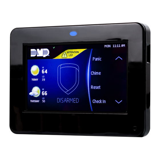
Page 9: Use The Keypad
USE THE KEYPAD Keypad Layout Armed/Power LEDs & Proximity Reader Dealer Logo microSD Card Slot Interactive Arming/ Disarming Press the Home Shield Navigation Arrows or touch and drag the menu to scroll Local Weather Carousel Menu Figure 6: Keypad Layout Enter Characters To see how to enter characters, watch the video How to Type on a Keypad. -
Page 10: Program The Panel
PROGRAM THE PANEL Before continuing with programming and setup, you’ll program the keypad in the panel as a device. To access the Programmer menu, reset the panel, press Keypad in the carousel menu, enter 6653 (PROG), then press CMD. After completing each of the following steps, press CMD to advance to the next option. Refer to the panel programming guide as needed. -
Page 11: Program The Keypad
PROGRAM THE KEYPAD Refer to the appropriate panel programming guide as needed. Keep in mind that operation for some programming options is restricted to the appropriate model. To access the Keypad Options menu, press Options in the carousel menu. Press the Installer Options wrench icon, enter 3577 (INST), then press CMD. KEYPAD OPTIONS KPD KPD OPT DIAG... -
Page 12: Card Options
Card Options CARD OPTIONS DMP CUSTOM Select DMP to allow credentials that use a 26-45 bit data string. The menu advances to REQUIRE SITE. Select CUSTOM to disable DMP format and program slots 1-8 as needed. The menu advances to FORMAT NO. Select ANY to allow all Wiegand card reads to activate the door strike relay. -
Page 13: Require Site Code
Site Code Position and Length SITE CODE POS: 1 LEN: 8 Enter the site code start position and length in the data string. Press select area 2 to clear the site code start position and enter a number between 0-255. Press CMD to save. -
Page 14: No Communication With Panel
No Communication with Panel NO COMM WITH PNL Define the relay action when communication with the panel has not occurred for 5 seconds: OFF, SITE, ANY, ON, or LAST. Default is OFF. Press any select key or area to change the default relay action: Press the first select key or area to choose OFF (Relay Always Off). -
Page 15: Dealer Info
Dealer Info DEALER INFO DELETE Select ADD at the DEALER INFO prompt to include information about the dealer when the logo is pressed. The keypad displays ADDING INFO SURE? to confirm the selection. Press YES to proceed. Adding Info Sure? ADDING INFO While the info is being uploaded to the keypad, the keypad displays ADDING INFO. -
Page 16: Select Language
Select Language Select Language allows you to select the language for text on the home screen, the carousel menu screens, and some programming screens. Press a box to select a language and a check mark displays. Press that box again to deselect that option. Only one language can be selected at a time. -
Page 17: Test The Keypad
TEST THE KEYPAD Test the keypad to ensure keypad lighting, individual shortcut keys, and any programmed zones work properly. Access the Keypad Diagnostics menu by pressing Options in the carousel menu. Press the Installer Options or wrench icon and enter 3577 (INST) and press CMD. KEYPAD DIAGNOSTICS KPD KPD OPT DIAG... -
Page 18: Train Your Customers
TRAIN YOUR CUSTOMERS This section contains instructions on how users can arm and disarm their system, use access control, and entry delay. All of the examples displayed assume that CLOSING CODE is YES in panel programming. For more information about using your system, refer to the appropriate system user guide. Access the User Menu In the Carousel Menu, select Keypad. -
Page 19: Use Access Control
Use Access Control Access an Area with a Door Strike If the Door Strike Relay was wired and programmed at the keypad, present a credential to the proximity reader. Once the system validates the card, the Door Strike Relay activates. See Figure 16. System Armed System Ready Panic... -
Page 20: Change System Wi-Fi Password
Change System Wi-Fi Password When you change your network’s Wi-Fi password, the system detects that the password has changed and asks you to update it. To close the Incorrect WiFi Password dialog and return to the main menu, tap the Shield icon. To reopen the dialog from the main menu, tap the Wireless icon. -
Page 21: Icons
Icons Arming Shield Icons Quick Arm Armed Alarm Home Sleep Away Perimeter All System Burglary Fire Ready To Exit Exit Timer Popups Menu Enter Code Arm Instant Attention List Alert Home Installer Navigation Edit Clean Screen Arming Options Panic Options Home Sleep Away... -
Page 22: Reference
REFERENCE Replace the Keypad Battery Disconnect the battery lead connector from the keypad battery header. Remove the standby battery from the PCB. Observe polarity and connect the battery lead connector to the keypad battery header. Place the new battery on the keypad PCB using double-sided mounting tape. See Figure 20. Battery Figure 20: Replace the Battery Requirements for Listed Installations... -
Page 23: Compatibility
Compatibility ▶ XTLplus/XTLtouch Series Panels ▶ XT30/XT50 Series Panels ▶ XR150/XR550 Series Panels Public Card Formats WIEGAND SITE CODE SITE CODE USER CODE USER CODE USER CODE CARD FORMAT CODE LENGTH POSITION LENGTH POSITION LENGTH DIGITS H10301 26 BIT H10302 37 BIT W/O H10304 37 BIT W/FAC FARPOINTE 39 BIT... -
Page 24: Ordering Information
9862-USB-W Wireless Graphic Touchscreen Keypad, Micro-USB (white, prox reader) Accessories Batteries 9800BAT2400/8 Replacement Battery for 9800 Series Keypads (3.8 V, 2400 mAh, 8 pack) Wiring Harnesses and Power Supplies 300-9800-4 Replacement 4-Wire Keypad Harness 300-9800-PWR Replacement Power Harness (Hardware Level 101 and higher) -
Page 25: Specifications
SPECIFICATIONS Operating Voltage 12 VDC Standby Current 120 mA at 12 VDC Alarm Current 206 mA at 12 VDC Dimensions 5.8” W x 4.135” H x 0.6” D CERTIFICATIONS ▶ FCC Part 15: CCKPC0132 ▶ Industry Canada: 5251A-PC0132 Intertek (ETL) Listed ANSI/UL 1023 Household Burglar ANSI/UL 1076...
Need help?
Do you have a question about the 9800 Series and is the answer not in the manual?
Questions and answers