DMP Electronics 9800 Series Installation And Programming Manual
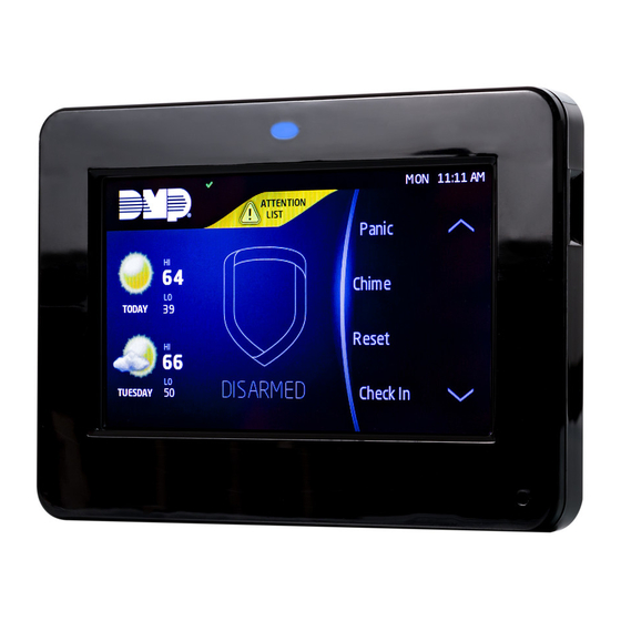
Graphic touchscreen keypad
Hide thumbs
Also See for 9800 Series:
- Installation and programming manual (48 pages) ,
- Installation manual (25 pages) ,
- Quick start manual (2 pages)

Related Manuals for DMP Electronics 9800 Series


Summary of Contents for DMP Electronics 9800 Series
- Page 1 9800 Series Graphic Touchscreen Keypad INSTALLATION AND PROGRAMMING GUIDE System Armed Panic CURRENT Chime 98 77 98 77 TODAY Reset ARMED Favorites 85 68 WEDNESDAY MON 5:35 PM MON 5:35 PM...
-
Page 3: Table Of Contents
TABLE OF CONTENTS About the Keypad ......1 Additional Programming .... 25 Update the Keypad ..........25 Keypad Features ......2 Credential Compatibility ........26 Programmable Carousel Menu .......3 End User Training ......27 Enter Characters ......4 Arm and Disarm the System ......27 Select a Location ......6 Replace the Keypad Battery ......29 Install the Keypad ......7... -
Page 5: About The Keypad
ABOUT THE KEYPAD 9800 Series Wireless Graphic Touchscreen Keypads offer flexible features and functionality. Each keypad provides: • AC Power/Armed LED • Full color touchscreen display • Built-in proximity card reader • Internal speaker • Wireless communication • 12 VDC plug-in power supply (9862) and wire harness •... -
Page 6: Keypad Features
Shield the menu to scroll CURRENT Chime 98 77 98 77 TODAY Reset Local Weather ARMED Favorites 85 68 WEDNESDAY MON 5:35 PM MON 5:35 PM Figure 1: Keypad Features 9800 Series Installation and Programming Guide... -
Page 7: Programmable Carousel Menu
Display In Menu to select that option to display in the carousel menu. Press that box again to deselect that option. See Figure 2. MODEL NUMBER 9800 V110 0961017 Display In Menu Brightness Chime Tone Reset Easy Exit Volume Check In Figure 2: Keypad Options 9800 Series Installation and Programming Guide... -
Page 8: Enter Characters
Press ABC to enter uppercase letters. • Press abc to enter lowercase letters. • Press !@# to enter special characters. • Press 123 to enter numbers and to return to the number pad. See Figure 4. • 9800 Series Installation and Programming Guide... - Page 9 Return to Home Screen Select Areas Special Characters ENTER CODE: Uppercase/ Lowercase Letters Number Pad Figure 3: Number Pad Figure 4: Standard Keyboard 9800 Series Installation and Programming Guide...
-
Page 10: Select A Location
SELECT A LOCATION 9800 Series Wireless Graphic Touchscreen Keypads provide a built–in survey capability to allow one person to confirm keypad communication with the wireless receiver or panel. This allows you to determine the best location for the keypad. Press Options in the carousel menu. -
Page 11: Install The Keypad
Repeat with the Base other slot. Separate the cover from the base and set the cover containing the keypad components aside. See Figure 5. Figure 5: Separate the Keypad Housing 9800 Series Installation and Programming Guide... -
Page 12: Install The 9862 Keypad
Plug in the power supply. Connect the other end of the power supply harness to the 4-pin power connector on the keypad without removing the PCB from the keypad housing, and snap the keypad into the base 9800 Series Installation and Programming Guide... - Page 13 Figure 6: Install the 9862 Keypad 9800 Series Installation and Programming Guide...
-
Page 14: Install The 9862Usb Keypad
Place the outlet screw through the hole in the plastic strap and secure it into the outlet. Plug the micro USB end of the cable into the back of the keypad. See Figure 9. 9800 Series Installation and Programming Guide... - Page 15 Transformer and Strap Figure 8 Figure 7 Micro Figure 9 9800 Series Installation and Programming Guide...
-
Page 16: Connect The Keypad
Reset the panel three times. The yellow LED at the top of the panel will begin flashing between each press. Wait for sixty seconds. When communication is confirmed, the LED will turn green and will stay on steady. 9800 Series Installation and Programming Guide... - Page 17 Device Setup Program the keypad as a device in DEVICE SETUP. Enter the eight-digit SERIAL# and continue to program the device as directed in the appropriate panel programming guide. 9800 Series Installation and Programming Guide...
-
Page 18: Program The Keypad
Use this option to enable or disable the panic keys. Press the icon name: PN (panic), EM (emergency), and FI (fire). Once the panic option is enabled, an asterisk displays next to the selected option(s). 9800 Series Installation and Programming Guide... - Page 19 H/S/A system. Default is 2. Enable Tamper ENABLE TAMPER? If the keypad is mounted on a wall, select YES to enable the NO YES wall tamper. Default is NO. 9800 Series Installation and Programming Guide...
-
Page 20: Custom Card Format
Other private or custom formats may also be compatible. Please contact the credential supplier or manufacturer for the bit structure. Format Name FORMAT NAME Press any select area to rename the card format. Press CMD to *UNUSED* save and advance. 9800 Series Installation and Programming Guide... - Page 21 0 1 1 1 0 1 0 1 1 0 1 1 0 1 0 1 0 0 0 1 1 0 0 1 1 1 First Bit User Code Site Code Last Bit Received Position=9 Position=1 Received Length=16 Position=0 Length=8 Position=25 Figure 10: Data Stream Bit Location Example 9800 Series Installation and Programming Guide...
- Page 22 NO OF USER CODE DIGITS. Default is NO. In addition to user code verification, door access is only granted when any one site code programmed at SITE CODE matches the site code received in the Wiegand string. 9800 Series Installation and Programming Guide...
- Page 23 Press the first select area to choose OFF (Relay Always Off). CHOOSE ACTION The relay remains off when any Wiegand string is received. OFF SITE ANY ON OFF does not affect any REX operation. 9800 Series Installation and Programming Guide...
- Page 24 After choosing the action, NO COMM W PANEL and the defined action display in the keypad. Keypad programming is complete. See Additional Programming to program a credential into the keypad. 9800 Series Installation and Programming Guide...
- Page 25 DEALER INFO Select ADD at the DEALER INFO prompt to include DELETE information about the dealer when the logo is pressed. The keypad displays ADDING INFO SURE? to confirm the selection. Press YES to proceed. 9800 Series Installation and Programming Guide...
-
Page 26: Carousel Z-Wave Items
Press CMD at the bottom of the screen to advance to the next options screen and the back arrow return to the previous screen. Default is no items selected. See Figure 11. Figure 11: Carousel Z-Wave Items 9800 Series Installation and Programming Guide... -
Page 27: Shortcut Items
Only one language can be selected at a time. Default is English. French Czech Note: The keypad does not translate information from the panel that displays on the keypad screen. See Figure 13. Figure 13: Select Language 9800 Series Installation and Programming Guide... -
Page 28: Test The Keypad
The display shows OKAY each time a good proximity read is received. Exit the Installer Options Menu Press CMD until the display returns to the Installer Options screen. Select STOP to exit the Installer Options menu. 9800 Series Installation and Programming Guide... -
Page 29: Additional Programming
Press CMD until RESTART KEYPAD displays. Press RESTART. Do not remove the Micro SD card or disrupt power. 10. When the keypad is finished restarting and returns to the home screen, remove the Micro SD card. 9800 Series Installation and Programming Guide... -
Page 30: Credential Compatibility
Public Card Formats. Note: Some proximity credentials are not compatible with DMP proximity keypads. Test the intended proximity credentials with the application before installation. DMP does not guarantee compatibility with credentials not purchased from DMP. 9800 Series Installation and Programming Guide... -
Page 31: End User Training
If a user code is required to arm: Enter your user code. Press the select key under the preferred option. Type in your user code to disarm the system. Once validated by the system, the selected areas arm or disarm automatically. 9800 Series Installation and Programming Guide... - Page 32 If ENTER CODE: - displays, enter a user code at the keypad or present a credential to the proximity reader. If disarming, enter a user code at ENTER CODE: - or present a credential to the proximity reader. 9800 Series Installation and Programming Guide...
-
Page 33: Replace The Keypad Battery
Observe polarity and connect the battery lead connector to the keypad battery header. Place the new battery (DMP Model 9800BAT) on the keypad PCB using double-sided sticky tape. See Figure 15. Battery Connection Battery Figure 15: Replace the Battery 9800 Series Installation and Programming Guide... -
Page 34: Public Card Formats
CODE CODE CODE LENGTH POSITION LENGTH POSITION LENGTH DIGITS HID H10301 26 HID H10302 37 BIT W/FAC HID H10304 37 BIT W/O FAC FARPOINTE 39 BIT CORPORATE 1000 35 BIT CORPORATE 1000 48 BIT 9800 Series Installation and Programming Guide... -
Page 35: Credentials
125 KHZ PROXIMITY CREDENTIALS PSC-1 STANDARD LIGHT PROXIMITY CARD PSK-3 PROXIMITY KEY RING PSM-2P ISO IMAGEABLE PROXIMITY CARD 1306 PROX PATCH™ 1326 PROXCARD II® CARD 1346 PROXKEY III® ACCESS DEVICE 1351 PROXPASS® 1386 ISOPROX II® CARD 9800 Series Installation and Programming Guide... -
Page 36: Compliance Specifications
Alarm Current 206 mA at 12 VDC Dimensions 5.8”W x 4.135”H x 0.6D Compatibility XTLplus/XTLtouch Series Panels XT30/XT50 Series Panels XR150/XR550 Series Panels Accessories Power Harness Model 300-9800-4 Model 300-9800-PWR (for Level 101 or higher keypads) 9800 Series Installation and Programming Guide... -
Page 37: Certifications
CERTIFICATIONS FCC Part 15: CCKPC0132 Industry Canada: 5251A-PC0132 Intertek (ETL) Listed • ANSI/UL 985 Household Fire Warning • ANSI/UL 1023 Household Burglar • ANSI/UL 1076 Proprietary Burglar • ANSI/UL 1610 Central Station Burglar 9800 Series Installation and Programming Guide... -
Page 38: Fcc Information
Increase the separation between the equipment and receiver. • Connect the equipment into an outlet on a circuit different from that to which the receiver is connected. • Consult the dealer or an experienced radio/TV technician for help. 9800 Series Installation and Programming Guide... -
Page 39: Industry Canada Information
Information furnished is believed to be accurate and reliable. This information is subject to change without notice. 9800 Series Installation and Programming Guide... - Page 40 LT-1367 19144 1.01 © 2019 Digital Monitoring Products, Inc.
Need help?
Do you have a question about the 9800 Series and is the answer not in the manual?
Questions and answers