
Related Manuals for VeEX TX50e


Summary of Contents for VeEX TX50e
-
Page 1: Table Of Contents
TX50e e-Manual D07-00-009 REVA00 Page 1 of 30 TX50e e-Manual Table of Contents 1 About the analyzer 2 Technical specifications 2.1 Output Line interface 2.3 Input Line interface 2.4 Transmitter 2.5 Receiver 2.6 Results 2.7 LED indication 2.8 Software Features 2.9 Hardware platform... - Page 2 TX50e e-Manual D07-00-009 REVA00 Page 2 of 30 5.1 Main menu 5.2 Line interface 5.2.1 Mode 5.2.2 Frame structure 5.2.3 CRC-4 5.2.4 Line code 5.2.5 Transmitter synchronization 5.2.6 Long haul 5.2.7 Deviation 5.2.8 Test speed 5.2.9 Protective resistors 5.3 Test pattern 5.3.1 Send pattern...
- Page 3 TX50e e-Manual D07-00-009 REVA00 Page 3 of 30 5.6.2 CAS/MFAS 5.6.3 Frame monitoring 5.7 Insert errors 5.7.1 Error type 5.7.2 Speed 5.7.3 Count 5.7.4 Start/stop errors insertion 5.7.5 Alarm type 5.7.6 Time 5.7.7 Start/stop alarms generating 5.8 Pulse shape 5.8.1 Operation 5.8.2 Pulse shape monitoring...
-
Page 4: About The Analyzer
TX50e e-Manual D07-00-009 REVA00 Page 4 of 30 About the analyzer TX50e is an advanced compact handheld analyzer/generator for E1 communications. It can be use for installation, serve, and maintenance of 2Mbps transmission paths which contain voice, data service at 2.048 Mbps rate. - Page 5 TX50e e-Manual D07-00-009 REVA00 Page 5 of 30 Frame structure 2048 kbit/s G704 PCM 30, PCM31 with/without CRC-4 Test Pattern Pattern types Fixed: All 1, All 0, 1010 PRBS: 2n-1 where n = 6, 9, 11, 15, 23 Pattern Standard O.153...
-
Page 6: Receiver
TX50e e-Manual D07-00-009 REVA00 Page 6 of 30 Receiver Receiver Clock Clock source Recovered form received data stream Frame structure 2048 kbit/s G704 PCM 30, PCM31 with/without CRC-4 Test Pattern Pattern types Fixed: All 1, All 0, 1010 PRBS: 2n-1 where n = 6, 9, 11, 15, 23 Pattern Standard O.153... -
Page 7: Results
Timeslot 0 (FAS, NFAS) Timeslot 16 (MFAS) abcd signaling bits of all 30 channels All timeslots (frame) LED indication LEDs on TX50e’s front panel display following receiver conditions: Signal Presence Alarm Indication Signal (G.703) Frame Alignment Detected Multiframe Alignment Detected... -
Page 8: Hardware Platform
TX50e e-Manual D07-00-009 REVA00 Page 8 of 30 Software update Hardware platform External power Input 100-240V AC, 50/60 Hz Output 9V @ 0.8 A Battery power rated voltage 4.8V from interface USB Dissipation 8 Watt Autonomy mode 6 hours Interface Dimensions 85x155x40mm (6.1 x 3.34 x 1.57 in) - Page 9 TX50e e-Manual D07-00-009 REVA00 Page 9 of 30 Figure 3.1: Front panel LEDs Three-color LED indicators provide visual control for power supply, measurements and data receiving conditions. The color of any LED would denote the following: Green: Correct operation since LED reset.
-
Page 10: Led Indicators Description
TX50e e-Manual D07-00-009 REVA00 Page 10 of 30 “M”, “P” or “–“ symbols show state of measuring mode: “M” – measurements, “P” – pause, “–“ – no measurements at the moment. “S” or “–“ symbols show state of the test pattern transmission mode: ”S” – transmission, “–“ – no test pattern transmission. -
Page 11: Keyboard Description
Power On/Off: To switch the test set on/off press the button and hold it for 1-2 seconds. Specifications of the analyzer's components Power supply unit Provides TX50e analyzer power from the mains and the test set built-in rechargeable battery. Input: 100 - 240 V AC @ 50 - 60 Hz. Output: 9V DC @0.8A. -
Page 12: Preliminary Steps
Home menu. Operation Main menu User interface of the TX50e test set is a system of menus which provides easy and quick access to any application. The Home menu screen is shown at Figure 5.1. Figure 5.1: Home menu Use the cursor to navigate the menu. -
Page 13: Line Interface
TX50e e-Manual D07-00-009 REVA00 Page 13 of 30 Voice functions: It measures the tone signal level and frequency. The user can also set up parameters for voice channel listening or audio data transmission. Measurements: Provides the ability to measure basic performance parameters, G.821 and G.826/M.2100 parameters, and signal propagation delay. -
Page 14: Line Code
TX50e e-Manual D07-00-009 REVA00 Page 14 of 30 This function allows the analyzer to enable/disable CRC-4 error detection algorithm. Select one of the following values: On: If the function on the test set is able to measure CRC-4 errors in the received signal, and to send CRC-4 bits in transmitted signal. -
Page 15: Protective Resistors
TX50e e-Manual D07-00-009 REVA00 Page 15 of 30 Highlight a desired timeslot number with the cursor. Press ‘Enter’ to invert current status of the timeslot. Any timeslot marked with “*” symbol will be included in measured object. Press ‘F1’ to select all the time slots. -
Page 16: Invert Rx
TX50e e-Manual D07-00-009 REVA00 Page 16 of 30 The Byte 1, Byte 2, and Byte 3 fields allows user to define 24 bits of a user defined pattern. To edit these fields, move the cursor to the desired bytes and press ‘Enter.’ The digits will be highlighted with yellow color and use the function key to insert 0 (‘F1’) and 1 (‘F2’). -
Page 17: Voice Function Settings
TX50e e-Manual D07-00-009 REVA00 Page 17 of 30 Level This field displays measured level of received signal. Settings Press ‘Enter’ to entering to “Voice function settings” submenu. Voice function settings This submenu defines the Voice processing parameters. Figure 5.6: “Voice functions settings” menu... -
Page 18: Measurements
TX50e e-Manual D07-00-009 REVA00 Page 18 of 30 The CAS field specifies signaling group which will be inserted into CAS-bits field corresponding to the selected timeslot. Sensitivity The Sensitivity parameter provides control for microphone signal amplification. To change the amplification, use the ‘Enter’... -
Page 19: G821/G826/M2100
TX50e e-Manual D07-00-009 REVA00 Page 19 of 30 G821/G826/M2100: Tested path parameters measurements in compliance with ITU-T G.821, G.826/M.2100 recommendation. Propagation delay: Measure signal propagation delay for the tested channel. G821/G826/M2100 To start/stop the measurement session, press ‘F1.’ When the measurements are active, the “M” symbol will appear in the status bar. -
Page 20: Propagation Delay
TX50e e-Manual D07-00-009 REVA00 Page 20 of 30 To save and load previously saved measurement results, user ‘F3’ and ‘F4’ key. For most of the measured parameters the test set will display an accumulative counter (left column) and the matching error rate (right column). For example the “CODE” parameter (a counter or code errors) is displayed in left column;... -
Page 21: Fas/Nfas/Sa/Si
TX50e e-Manual D07-00-009 REVA00 Page 21 of 30 FAS/NFAS/Sa/Si View contents of FAS/NFAS words in last sixteen frames (see Figure 5.16). Use ‘F1’ to start/stop data update process. Use ‘F2’ to switch between FAS/NFAS and S-bits screens. Figure 5.15: “FAS/NFAS” submenu CAS/MFAS The CAS/MFAS submenu (Figure 5.16) provides the ability to view the contents of CAS/MFAS words in last... -
Page 22: Insert Errors
TX50e e-Manual D07-00-009 REVA00 Page 22 of 30 Figure 5.17: “Frame monitoring” menu Insert errors The Insert errors menu (see Figure 5.18) provides the ability to insert errors or generate alarms of different types. Figure 5.18: “Insert errors” menu Error type... -
Page 23: Alarm Type
TX50e e-Manual D07-00-009 REVA00 Page 23 of 30 Alarm type The Alarm type field allows the user to select type of alarm to be generated. LOS: Loss of Signal. AIS: Alarm Indication Signal. The transmitter will send all ones. LOF: Transmit loss of FRM synchronizing signal. -
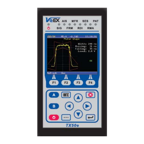
Page 24: Oscilloscope
TX50e e-Manual D07-00-009 REVA00 Page 24 of 30 Figure 5.19: Pulse shape screen Press ‘F1’ to update the screen. Press ‘F2’ to move to the Oscilloscope screen. Oscilloscope This is an optional function, it provides the ability to display a one-shot sample of the signal for the 4 interval with the frequency passband of 0.01…... -
Page 25: Jitter Measurements
TX50e e-Manual D07-00-009 REVA00 Page 25 of 30 This optional menu provides the following jitter processing functions: Jitter measurements: Measurements and analysis of jitter in received signal. Maximum Tolerable Jitter: Measure maximum tolerable jitter (MTJ) according to ITU-T G.823 recommendation. -
Page 26: Jitter Transfer Function
TX50e e-Manual D07-00-009 REVA00 Page 26 of 30 Press ‘F1’ to start/stop the measurement. Colors on the graphical diagram denote the following: White: White line displays the MTJ mask according to ITU-T G.823 recommendation. Green: Range of jitter values which are valid for tested path. -
Page 27: Configuration
TX50e e-Manual D07-00-009 REVA00 Page 27 of 30 Define parameter step value Press ‘F1’ to start/stop the generating process. Figure 5.25: “Jitter generation” submenu The “Jitter generation” submenu shows following parameters: Transmit Generated jitter parameters: Frequency – Transmitted jitter frequency (20Hz... 100 kHz). -
Page 28: Line Interface
TX50e e-Manual D07-00-009 REVA00 Page 28 of 30 Figure 5.27: “Basic settings” This submenu allows the user to set up following parameters: Time: Current time Date: Current date Meas. time: Measurement session duration. This parameter allows the user to define the period for automatic measure stop. -
Page 29: Calibration Mode
Replace the hardware which prove to be defective provided that the products that the customer elects to replace is returned to VeEX Inc by the customer along with proof of purchase within thirty (30) days of the request by the customer, freight prepaid. -
Page 30: About Veex
(hardware, software, firmware and/or accessories) Revoking the warranty: VeEX Inc does not guaranty or warrant that the operation of the hardware, software or firmware will be uninterrupted or error-free. The warranty will not apply in any of the following cases:...
Need help?
Do you have a question about the TX50e and is the answer not in the manual?
Questions and answers