Table of Contents
Advertisement
Quick Links
Advertisement
Table of Contents

Related Manuals for VeEX VePal CX350


Summary of Contents for VeEX VePal CX350
- Page 1 CX350 e-Manual D07-00-037 RevC01 Page 1 of 81...
-
Page 2: Table Of Contents
CX350 e-Manual D07-00-037 RevC01 Page 2 of 81 Table of Contents 1.0 About this User Manual 2.0 Product Introduction 3.0 Safety Information 4.0 Basic Operation 4.1 Compact Platform Overview 4.2 Keypad 4.3 Touch-Screen Display 4.4 Battery 4.5 Connector Panels 4.5.1 Test Ports 4.5.2 Utility Ports 5.0 Home Screen and Menu 5.1 Screen Layout... - Page 3 CX350 e-Manual D07-00-037 RevC01 Page 3 of 81 7.3 System Scan 7.4 Spectrum Analysis 7.5 Cable Modem 7.6 Upstream Signal Generator (USG) 7.7 Installation Check 7.8 Advanced Tools 7.8.1 Return Path Analysis 7.8.2 Sweep Operations 7.8.3 Remote Operations 7.8.4 R-Server 7.8.5 RP Balancing 7.8.6 TDR 7.8.7 DS1...
- Page 4 10.3.1 USB File Transfer 10.3.2 FTP File Transfer 11.0 Setup - Main Menu 12.0 ReVeal Software 12.1 Profiles 12.2 Results 12.3 Software 12.4 Tools 13.0 Warranty and Software 14.0 Product Specification 15.0 Certification and Declarations 16.0 About VeEX Go back to top...
- Page 5 CX350 e-Manual D07-00-037 RevC01 Page 5 of 81...
-
Page 6: About This User Manual
This user manual is suitable for novice, intermediate, and experienced users and is intended to help you successfully use the features and capabilities of the VePAL CX350 test set. It is assumed that you have basic computer experience and skills, and are familiar with IP and telecommunication concepts, terminology, and safety. -
Page 7: Product Introduction
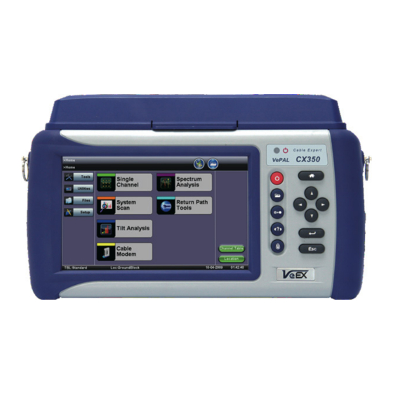
2.0 Product Introduction The VeEX™ VePal CX350 is a next generation test solution for analog and digital cable TV networks. The unit is a lightweight, rugged and weather resistant instrument featuring Analog and Digital signal level meter capabilities and is equipped with enhanced spectrum, forward and return path analysis functions. -
Page 8: Safety Information
Do not operate the instrument in the presence of flammable gases or fumes or any other combustible environment. VeEX Inc. assumes no liability for the customer's failure to comply with safety precautions and requirements. -
Page 9: Basic Operation
CX350 e-Manual D07-00-037 RevC01 Page 9 of 81 4.0 Basic Operation 4.1 Compact Platform Overview 4.2 Keypad 4.3 Touch-Screen Display 4.4 Battery 4.5 Connector Panels 4.5.1 Test Ports 4.5.2 Utility Ports 4.1 Compact Platform Overview Go back to top Go back to TOC 4.2 Keypad The keypad comprises the following keys: Power key: The unit is powered on and off from the red key on the keypad. -
Page 10: Touch-Screen Display
CX350 e-Manual D07-00-037 RevC01 Page 10 of 81 History key: The history key resets any blinking LED due to a history condition. Help key: The help key brings the user to the online help, regardless of the current user interface location of the unit. Lock key: Locks the keypad Home key: Bring the unit to its home menu regardless of its location on the user interface. - Page 11 CX350 e-Manual D07-00-037 RevC01 Page 11 of 81 Go back to top Go back to TOC 4.5 Connectors and Panels The connector panel located at the top of the unit comprises the following test ports (some are optional):...
-
Page 12: Test Ports
CX350 e-Manual D07-00-037 RevC01 Page 12 of 81 4.5.1 Test Ports Test Ports: To access the test connectors, please open the top cover. RF-in "F" Connector, 75 ohms for connection to the CATV network - Provides access to: Signal Level Meter (SLM) and associated functions Reverse Path QAM analyzer Note: Maximum Voltage input is 100VAC, 140VD Cable Modem:... - Page 13 CX350 e-Manual D07-00-037 RevC01 Page 13 of 81 Go back to top Go back to TOC...
-
Page 14: Home Screen And Menu
CX350 e-Manual D07-00-037 RevC01 Page 14 of 81 5.0 Home Screen and Menu 5.1 Screen Layout 5.2 Screen Icons 5.1 Screen Layout The Home menu can be accessed at anytime during operation by pressing the Home key on the rubber keypad. The screen is divided into three presentation areas: Left: Tools... -
Page 15: Screen Icons
CX350 e-Manual D07-00-037 RevC01 Page 15 of 81 Go back to top Go back to TOC 5.2 Screen Icons The following icons are displayed and located at the top of the screen: Power: Indicates if the unit is being powered by the internal Li-ion battery or external AC power. Tap the icon for battery status if running on battery. - Page 16 CX350 e-Manual D07-00-037 RevC01 Page 16 of 81 Go back to top Go back to TOC...
-
Page 17: Setup
CX350 e-Manual D07-00-037 RevC01 Page 17 of 81 6.0 Setup 6.1 Channel Tables and Locations 6.1.1 Channel Tables 6.1.2 Locations 6.1.3 Test Point Compensation Test mode, test port/s and network settings are required prior to performing any measurements or applications. Go back to top Go back to TOC 6.1 Channel Tables and Locations 6.1.1 Channel Tables... - Page 18 CX350 e-Manual D07-00-037 RevC01 Page 18 of 81 Channel Table Selection Select a table and press the Edit button Channel Table Editing...
- Page 19 CX350 e-Manual D07-00-037 RevC01 Page 19 of 81 Creating Channel Tables with ReVeal CX300 Alternatively, the channel tables can be created and managed using ReVeal CX300 PC software, which is a standard accessory. Additional tables can be created from a blank table or from existing templates. The test set and the PC software can exchange the tables for easy update.
- Page 20 CX350 e-Manual D07-00-037 RevC01 Page 20 of 81 Go back to top Go back to TOC 6.1.3 Test Point Compensation Test point compensation allows the loss at a certain test point to be automatically compensated. When performing a measurement, one of these preset test points can be selected by tapping the check box. The CX350 stores 10 sets of TP compensation value by name.
- Page 21 CX350 e-Manual D07-00-037 RevC01 Page 21 of 81 Location Editor Location Editor - Digital...
- Page 22 CX350 e-Manual D07-00-037 RevC01 Page 22 of 81 Go back to top Go back to TOC...
-
Page 23: Test Applications
CX350 e-Manual D07-00-037 RevC01 Page 23 of 81 7.0 Test Applications 7.1 Single Channel Measurement 7.1.1 Analog Channel Measurements 7.1.2 Digital Channel Measurements 7.1.3 Constellation Measurements 7.1.4 Impairment Measurements 7.2 Tilt Analysis 7.3 System Scan 7.4 Spectrum Analysis 7.5 Cable Modem 7.6 Upstream Signal Generator (USG) 7.7 Installation Check 7.8 Advanced Tools... - Page 24 CX350 e-Manual D07-00-037 RevC01 Page 24 of 81 Note: The red blocks indicate the predefined threshold window for the measurement parameter The affect of noise or poor C/N on analog video carriers is described below. Note: The average power changes depending on the picture content e.g. dark scenes have a higher average power than bright scenes. Using the sync pulses, the carrier is at its peak power and it does not change from scene to scene;...
- Page 25 CX350 e-Manual D07-00-037 RevC01 Page 25 of 81 QAM Power Level in dBmV including graphic bar indication Modulation Error Ratio (MER) in dB Pre BER & Pre Error Second ratio Post BER & Post Error Second ratio Severely Error Second count Max Adjacent Channel Delta in dB SLM Measurement (Digital Carrier) SLM Measurement (Digital Carrier-Constellation)
- Page 26 CX350 e-Manual D07-00-037 RevC01 Page 26 of 81 Go back to top Go back to TOC 7.1.3 Constellation Measurements In contrast to the measuring techniques used on digital TV signals transmitted via satellite, a wider and necessary range of measuring techniques is provided for broadband cable testing.
- Page 27 CX350 e-Manual D07-00-037 RevC01 Page 27 of 81 The diagram is an X/Y plot of the I (In-phase) and Q (Quadrature) axis components of the QAM signal and is particularly useful for viewing impairments due to ingress and/or modulation problems present on the digital signal. A symbol (essentially a waveform representing one or more bits) should ideally appear as a compact or clean dot in the center of each symbol box.
- Page 28 CX350 e-Manual D07-00-037 RevC01 Page 28 of 81 Coherent interference - CSO/CTB, spurs or ingress produce symbol clusters with a hole in the center so they appear as "donuts". This can also be a result of laser clipping or sweep interference. Coherent Interference Phase noise - Also known as Phase jitter in a QAM signal, it is caused by transponders in the transmission path or by the I/Q modulator.
-
Page 29: Tilt Analysis
CX350 e-Manual D07-00-037 RevC01 Page 29 of 81 Go back to top Go back to TOC Equalized and Un-equalized MER measurements Un-equalized MER is typically measured before the adaptive equalizer and equalized MER is measured after the adaptive equalizer but often this circuitry resides in the QAM receiver and cannot be disabled. -
Page 30: System Scan
CX350 e-Manual D07-00-037 RevC01 Page 30 of 81 For the A&D Combined mode, a Normalize function is supported. This allows you to artificially boost the levels of Digital Carriers for Tilt Analysis. The default value is set at 6 dB. You can change the Normalize value by pressing the Set Norm. button. Tilt Scan Tilt Scan Go back to top Go back to TOC... -
Page 31: Spectrum Analysis
CX350 e-Manual D07-00-037 RevC01 Page 31 of 81 Go back to top Go back to TOC Digital Scan The following measurements will be performed for each digital channel: QAM Power Level in dBmV System Scan System Scan Once the test is completed or stop by the user, a marker is available and can be placed on any of the measured channel. The measurements of the selected channel are then displayed. - Page 32 CX350 e-Manual D07-00-037 RevC01 Page 32 of 81 Direct channel tuning and positioning of digital signal Survey of system digital channel levels System frequency response To understand the capabilities of the spectrum analyzer and the various elementary settings, it is important to have a basic understanding of how a spectrum analyzer operates.
- Page 33 CX350 e-Manual D07-00-037 RevC01 Page 33 of 81 Spectrum analysis is not overly complicated, but if you are not careful it is very easy to make mistakes. The following overview provides simple guidelines to accurately measure the amplitude of analog and digitally modulated carriers. Go back to top Go back to TOC 7.4.2 Amplitude Measurements Overview:...
-
Page 34: Cable Modem
CX350 e-Manual D07-00-037 RevC01 Page 34 of 81 Overview: Historic video channel assignments limit the upstream frequencies between 5 - 42 MHz (North America) and 5 - 65 MHz (Europe). The upstream spectrum supporting return path connectivity is frequently impaired by ingress of interfering signals, such as radio citizen band (CB), and other legitimate and non-legitimate RF emissions. Reverse Ingress can be analyzed between 5 to 42 MHz (6 MHz channel plan) or 5 to 65 MHz (8 MHz channel plan). - Page 35 CX350 e-Manual D07-00-037 RevC01 Page 35 of 81 Go back to top Go back to TOC 7.5.1 Setup: The CX350 offers a built-in DOCSIS 3.0 cable modem as a selectable option. The built-in cable modem is able to range, register and connect with the headend CMTS to obtain the necessary parameters and a valid IP address on the network.
- Page 36 CX350 e-Manual D07-00-037 RevC01 Page 36 of 81 MAC Selection: supports two Cable Modem MAC Addresses. Typically use MAC1 for all tests. MAC Address: This can be set to default (a pre-programmed registered unique MAC address), or it can be manually entered to clone a specific customer modem. If manual is selected, tap on the MAC address field to enter your desired MAC address.
- Page 37 CX350 e-Manual D07-00-037 RevC01 Page 37 of 81 Cable Modem Connection Process 2 Server connections: DOCSIS specifies that for a system to become functional and operational, the CMTS and CM must interface with the following mandatory servers: Dynamic Host Configuration Protocol (DHCP) server - Defined by RFC2181, it provides the IP addresses for both the CM and subsequent PC devices that follow Time of Day (TOD) server - Defined by RFC868 for the purpose of time stamping operational system events Trivial File Transfer Protocol (TFTP) server - defined by RFC1350 for the purpose of registering and downloading CM configuration files for individual customer service.
- Page 38 CX350 e-Manual D07-00-037 RevC01 Page 38 of 81 Cable Modem - IP Results Go back to top Go back to TOC Link tab: Provides information about the packets received, the downstream signal (frequency, modulation, level, SNR) and about the upstream signal (frequency, level, modulation). Cable Modem - Link Results (Downstream) Go back to top Go back to TOC Cable Modem - Link Results (Upstream)
-
Page 39: Upstream Signal Generator (Usg)
CX350 e-Manual D07-00-037 RevC01 Page 39 of 81 Cable Modem - VeTest Go back to top Go back to TOC Pass Through tab: Provides the ability to emulate a real cable modem. In the Setup screen, select Pass Through for the Test Mode and press Connect. Once the Cable Modem goes online, connect a PC to the CX350 meter's 10/100/1000T RJ45 port at the top of the unit. -
Page 40: Installation Check
CX350 e-Manual D07-00-037 RevC01 Page 40 of 81 Note: Symbol Rate The symbol rate is the gross bit rate, inclusive of channel coding overhead, divided by the number of bits transmitted in each symbol. Symbol rate is measured in symbols-per-second, hertz (Hz), or baud (Bd). The USG function is a powerful application used to check and validate the reverse path for DOCSIS cable modem operation. -
Page 41: Advanced Tools
CX350 e-Manual D07-00-037 RevC01 Page 41 of 81 Go back to top Go back to TOC Results: During the test, a status indicator is displayed. Once completed, the yellow square is replaced by a green square if the measurements meet the location based thresholds, or a red square if the measurements fail to meet the location based thresholds. - Page 42 CX350 e-Manual D07-00-037 RevC01 Page 42 of 81 7.8.1.1 RP Level Measurements The following setups are displayed and measurements are calculated: Center Frequency (MHz) Symbol rate (symbols/second) Modulation type (QPSK, QAM-16, QAM-64, QAM-128, QAM-256) Digital Carrier Level in dBmV or dBuV Modulation Error Ratio (MER) in dB Pre-FEC rate Post FEC rate...
-
Page 43: Sweep Operations
CX350 e-Manual D07-00-037 RevC01 Page 43 of 81 Modulation type (QPSK, QAM-16, QAM-64, QAM-128) Digital Carrier Level in dBmV or dBuV Modulation Error Ratio (MER) in dB Pre-FEC rate Post FEC rate Pre Errored Seconds count Post Errored Seconds count Severely Errored Seconds count QAM Constellation (see below) Return Path QAM Constellation Measurement... -
Page 44: Remote Operations
64, 128 and 256 modulations, remote return path multi-port ingress monitor, and remote return path alignment with integrated CW generator. The following functions are available under the Remote Operations menu: Remote View: An optional feature to allow remote viewing of other VeEX CX devices. IGM Scan Monitor: To view a CX180R-IGM, the return path monitor system, current scanning spectrum. - Page 45 CX350 e-Manual D07-00-037 RevC01 Page 45 of 81 Built-in Cable Modem using existing HFC network (shown below) Data Card (3G mobile) WiFi hot spot 10/100-T network access Bluetooth via 3G mobile phone CX350 to CX180R Once the connection is established, the CX350 unit is able to do the following: Remotely monitors activities on all 10 nodes that are connected to a CX180R in IGM Scan Monitor mode.
- Page 46 CX350 e-Manual D07-00-037 RevC01 Page 46 of 81 3. After CX180R-IGM connection is made, tap Exit to return to the Main Menu and start Return Path Analysis and Spectrum Analysis. To stop the Remote View session, return to the Remote View menu to disconnect. USG Setup menu: Enter the USG test parameters, then press 'Start.' Tabs are available on the USG home screen to allow quick access of Spectrum Analysis mode and Return Path Analysis mode.
-
Page 47: Rp Balancing
The R-Server function is an optional feature that allows the CX350 to communicate with the CX-server for work force management. The CX Server offers the following capabilties: Works with VeEX CX field meters Convenient internet connection via WiFi, Ethernet, Cable Modem, USB 3G data modem, USB Bluetooth with mobile phone dialing... -
Page 48: Tdr
CX350 e-Manual D07-00-037 RevC01 Page 48 of 81 Go back to top Go back to TOC 7.8.6 TDR 7.8.6.1 Principles of Operation The TDR works on the same principle as radar where a pulse of energy is transmitted down a cable. When the pulse reaches a fault or the end of the cable, a portion or all of the pulse energy is reflected back to the instrument. - Page 49 CX350 e-Manual D07-00-037 RevC01 Page 49 of 81 Range: Select approximate distance Range for measurement. This selection automatically configures the TDR Pulsewidth. There are nine distance range scales, which automatically configure the pulsewidth appropriate for the range selected: 20 ft (7m) 45 ft (15m) 90 ft (30m) 180 ft (60m)
-
Page 50: Ds1
Typical Cable Vp and Impedance Values Go back to top Go back to TOC 7.8.7 DS1 Please contact VeEX Customer Care for more information. Go back to top Go back to TOC 7.8.8 OFDM The Japanese standard OFDM signal hardware optional feature. -
Page 51: Tools
CX350 e-Manual D07-00-037 RevC01 Page 51 of 81 8.0 Tools The V300 common tools 8.1 IP Tools 8.1.1 IP connection 8.1.2 Ping 8.1.3 Trace Route 8.1.4 Web/FTP 8.1.5 ARPwiz 8.1.6 VoIP 8.2 NetWiz 8.3 WiFiWiz 8.4 Advanced 8.4.1 ReVeal EZ connect 8.4.2 Packet capture 8.4.3 Fiber Scope 8.4.4 WiFi Spectrum Analyzer... - Page 52 CX350 e-Manual D07-00-037 RevC01 Page 52 of 81 Note: IP connection The user needs to establish an IP connection and address prior to Ping, Trace Route, Web/FTP, ARP Wiz, VoIP, and IPTV testing. Go back to top Go back to TOC Status IP Connection Status The following parameters are displayed:...
- Page 53 CX350 e-Manual D07-00-037 RevC01 Page 53 of 81 Go back to top Go back to TOC 8.1.2 Ping PING is a popular computer network tool used to test whether a particular host is reachable across an IP network. A Ping is performed by sending an “echo request”...
- Page 54 CX350 e-Manual D07-00-037 RevC01 Page 54 of 81 The following results are displayed: Ping status - Pass or Fail Destination IP address Number of Pings Sent Number of Pings Received Unreachable and Missing Pings PING also estimates the round-trip time, in milliseconds Current - The current time for a Ping request to be answered.
- Page 55 CX350 e-Manual D07-00-037 RevC01 Page 55 of 81 Go back to top Go back to TOC Trace Route results: The following results are displayed: Number of hops to destination Time to Live (TTL) Addresses up to the destination Note: If there is no response from a particular hop, an asterisk will be displayed. Trace Route Result Go back to top Go back to TOC 8.1.4 Web/FTP...
- Page 56 CX350 e-Manual D07-00-037 RevC01 Page 56 of 81 For FTP download or upload, the user needs to configure: Mode - Select between FTP or Web mode FTP mode - Displayed when FTP is selected. Select either Upload or Download Profile - Recall a FTP profile or create a new FTP test session Address - Enter IP address of the FTP server File/Path - Enter any file path, if applicable User name - Enter user name needed to login into server...
- Page 57 CX350 e-Manual D07-00-037 RevC01 Page 57 of 81 Web Setup Users can either configure the Internet browser settings or settings to conduct a Web Test. Web Test is used to verify that the Internet is properly provisioned at the service point. Setup: To perform a Web Test, follow the procedure below: Mode - Select Web Test from Mode selection...
- Page 58 CX350 e-Manual D07-00-037 RevC01 Page 58 of 81 Response time - Current, Average, Minimum and Maximum values Transfer time - Current, Average, Minimum and Maximum values Data transfer Average Throughput Web Test Result Go back to top Go back to TOC Web Browser: Select Browser from Web Mode Enter or select the desired IP address or URL destination and encoding, then press ‘Browse’...
- Page 59 CX350 e-Manual D07-00-037 RevC01 Page 59 of 81 ARP Wiz uses the Address Resolution Protocol (ARP) to verify the status of each IP address in a user-selectable IP range. ARP is the standard method for finding a host's hardware address when only its network layer address is known. In other words, ARP is used primarily to translate IP addresses to Ethernet MAC addresses.
- Page 60 CX350 e-Manual D07-00-037 RevC01 Page 60 of 81 Note: ARP The ARP protocol only works within the same subnet as the IP address provided to the test set in IP Status. Go back to top Go back to TOC 8.2 Net Wiz The Net Wiz function allows you to test the Ethernet cable and associated network environment.
- Page 61 CX350 e-Manual D07-00-037 RevC01 Page 61 of 81 Received frames in error Speed advertized Duplex mode advertised Number of devices and networks found Discovery Result: Devices tab indicates: Total number of devices found Number of devices i.e. routers, servers or hosts Attribute of each device discovered, including Ping test result Discovery Result: Networks tab indicates:...
- Page 62 CX350 e-Manual D07-00-037 RevC01 Page 62 of 81 network key is required to complete the connection. The WiFi function supports WEP encryption. The key can either be 10 characters or 26 characters. Note: If the user enters the wrong network key, the test set will still connect to the Access Point; however, it will not be able to connect to the web or perform the Ping test.
- Page 63 CX350 e-Manual D07-00-037 RevC01 Page 63 of 81 8.4 Advanced The Advanced tab under Tools offers the following tools: ReVeal EZ Connect Packet Capture Fiber Scope WiFi Spectrum Analyzer Data Card/GPS Signature Pad For more information on these tools refer to the V300 Common Functions Manual. 8.4.1 ReVeal EZ Connect The ReVeal EZ connect feature can be used to quickly connect your PC running ReVeal software to your VePAL device for stored results and profile management or remote control application.
- Page 64 CX350 e-Manual D07-00-037 RevC01 Page 64 of 81 Go back to top Go back to TOC...
-
Page 65: Utilities
CX350 e-Manual D07-00-037 RevC01 Page 65 of 81 9.0 Utilities This section provides settings for the global parameters of the test set. 9.1 About 9.2 Screen 9.3 Bluetooth 9.4 Power 9.5 Backlight 9.6 Global 9.7 Date and Time 9.8 Remote Access Go back to top Go back to TOC 9.1 About This section provides information about the software version, serial number, Management MAC address and Test MAC addess of... -
Page 66: Screen
CX350 e-Manual D07-00-037 RevC01 Page 66 of 81 Go back to top Go back to TOC 9.2 Screen This provides the utility to calibrate the touch screen when out of calibration. Go back to top Go back to TOC 9.3 Bluetooth This provides the utility to setup Bluetooth paring. -
Page 67: Global
CX350 e-Manual D07-00-037 RevC01 Page 67 of 81 This provides backlight control of the unit. Power: There are two settings -- one for Battery power and one for AC power. The user has the option to select a timer to turn off the backlight if the unit is not in use. This function helps improve the battery autonomy and preserve LCD life. -
Page 68: Date And Time
CX350 e-Manual D07-00-037 RevC01 Page 68 of 81 Language: An alternative language for the user interface Units: Measurement system (English - feet or Metric - meter) Audible Alarm: On or Off Show Password: Hides/unhides username and password information associated with FTP and related IP functions Color Scheme: General or High Contrast. -
Page 69: Remote Access
CX350 e-Manual D07-00-037 RevC01 Page 69 of 81 Go back to top Go back to TOC 9.8 Remote Access To set remote VNC access. Go back to top Go back to TOC... -
Page 70: Files (Test Results)
CX350 e-Manual D07-00-037 RevC01 Page 70 of 81 10.0 Files (Test Results) The CX350 saves the Files (Test Results) in the unit's internal memory (an SD card) for recall and viewing. 10.1 Saving Files 10.2 Recalling Files 10.3 File Transfer 10.3.1 USB File Transfer 10.3.2 FTP File Transfer 10.1 Saving Files... -
Page 71: File Transfer
CX350 e-Manual D07-00-037 RevC01 Page 71 of 81 Go back to top Go back to TOC 10.3 File Transfer The test result files are saved in the HTML format. To archive, print or generate test reports, please export or transfer the files using one of the following methods. -
Page 72: Setup - Main Menu
CX350 e-Manual D07-00-037 RevC01 Page 72 of 81 11.0 Setup - Main Menu This menu contains CX350 related system operation and parameter settings: Channel Table Default Location CM SNR To turn Cable Modem SNR measurement results On or Off. When turned On, the Cable Modem’s SNR measurement results will be displayed and saved. - Page 73 CX350 e-Manual D07-00-037 RevC01 Page 73 of 81 Go back to top Go back to TOC...
-
Page 74: Reveal Software
CX350 e-Manual D07-00-037 RevC01 Page 74 of 81 12.0 ReVeal Software Please install the ReVeal CX300 software (supplied with the instrument) onto your PC. The ReVeal software offers the following functionalities: Create, Edit and Manage Test Profiles, Channel tables and Location thresholds 12.1 Profiles: Download and Manage test results, generate Test Reports 12.2 Results:... -
Page 75: Results
CX350 e-Manual D07-00-037 RevC01 Page 75 of 81 Go back to top Go back to TOC 12.2 Results The Results menu allows you to: Download Results Manage Results Create Reports Convert Results to PDF format Convert Results to CSV format Print Results ReVeal CX350 - Results Menu... -
Page 76: Software
Go back to top Go back to TOC 12.3 Software The Software menu allows you to: Download software from the VeEX website to upgrade the test set Enable or Disable software options Check Test set configuration Upgrade the Test set software... - Page 77 CX350 e-Manual D07-00-037 RevC01 Page 77 of 81 Go back to top Go back to TOC 12.4 Tools - Remote Control Launch the ReVeal CX software on your PC to remote control the instrument. The test instrument must be connected to the PC via an IP connection.
-
Page 78: Warranty And Software
Replace hardware which prove to be defective provided that the products that the customer elects to replace are returned to VeEX Inc. by the customer, along with Proof of Purchase, within thirty (30) days of the request by the customer, freight prepaid. -
Page 79: Product Specification
CX350 e-Manual D07-00-037 RevC01 Page 79 of 81 14.0 Product Specifications The most recent product specifications can be downloaded from the VeEX website. For the most recent version, click here Go back to top Go back to TOC... -
Page 80: Certification And Declarations
Use of this logo implies that the the unit conforms to requirements of European Union and European Free Trade Association (EFTA). EN61010-1 Click here for CE Declaration of Conformity relating to VeEX products What is RoHS? RoHS is the acronym for Restriction of Hazardous Substances. Also known as Directive 2002/95/EC, it originated in the European Union and restricts the use of specific hazardous materials found in electrical and electronic products. -
Page 81: About Veex
Page 81 of 81 16.0 About VeEX VeEX, Inc., the Verification EXperts, is an innovative designer and manufacturer of test and measurement solutions addressing numerous technologies. Global presence through a worldwide distribution channel provides uncompromised product support. Visit us online at www.veexinc.com...
Need help?
Do you have a question about the VePal CX350 and is the answer not in the manual?
Questions and answers