Table of Contents
Advertisement
Quick Links
Advertisement
Table of Contents

Related Manuals for EAE EE-MR35


Summary of Contents for EAE EE-MR35
- Page 1 Model No. EE-MR35 Installation, Operation Short Platform Scissor Lift, Mid Rise and Parts Manual Lifting Capacity, 3500KG Electrical Release Distributed by Please read this entire manual carefully and completely before installation or operation of the lift. Date:07/07/2021...
-
Page 2: Table Of Contents
Installation, Operation and Parts Manual EE-MR35 IMPORTANT NOTES ................................3 SAFETY NOTES ..................................4 1.1 Operation of lifting platforms ............................4 1.2 Checking of the lifting platforms ............................4 1.3 Important safety notices ..............................5 1.4 Warning labels ................................. 6 1.5 Potential safety risks ................................ -
Page 3: Important Notes
Liability The liability of EAE is limit to the amount that the customer has actually paid for this product. This exclusion of liability does not apply to damages caused through willful misconduct or gross negligence on the part of EAE. -
Page 4: Safety Notes
Installation, Operation and Parts Manual EE-MR35 SAFETY NOTES 1.1 Operation of lifting platforms This lift is specially designed for lifting motor vehicles. Users are not allowed to use it for any other purposes. The applicable national regulations, laws and directives must be observed. -
Page 5: Important Safety Notices
Installation, Operation and Parts Manual EE-MR35 engineering to be able to check and give an expert option on lifting platforms. 1.3 Important safety notices 1.3.1 Recommend for indoor use only. DO not expose the lift to rain, snow or excessive moisture. -
Page 6: Warning Labels
Installation, Operation and Parts Manual EE-MR35 1.4 Warning labels All safety warning labels are clearly depicted on the lift to ensure that the operator is aware of and avoid the dangers of using the lift in an incorrect manner. The labels must be kept clean and they have to be replaced if detached or... -
Page 7: Potential Safety Risks
Installation, Operation and Parts Manual EE-MR35 1.5 Potential safety risks 1.5.1 Mains voltage nsulation damage and other faults may result in accessible components being live Safety measures: Only ever use the power cord provided or a tested power cord. -
Page 8: Packing, Storage And Transportation
Installation, Operation and Parts Manual EE-MR35 PACKING, STORAGE AND TRANSPORTATION Packing, lifting, handling, transporting operations must be performed only by experienced personnel with appropriate knowledge of the lift and after reading this manual. 2.1 The lift was dismantled into 3 parts for transportation... -
Page 9: Product Descriptions
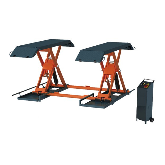
Installation, Operation and Parts Manual EE-MR35 PRODUCT DESCRIPTIONS 3.1 General descriptions This model is chassis supporting vehicle lift for road vehicles. It is driven by an electro-hydraulic system and designed for mobile use with a maximum lifting height of 1000mm. The gear pump delivers hydraulic oil to oil cylinders and pushes upwards pistons to raise the platforms. -
Page 10: Dimensions
Installation, Operation and Parts Manual EE-MR35 3.3 Dimensions... -
Page 11: Safety Device Descriptions
Installation, Operation and Parts Manual EE-MR35 3.4 Safety device descriptions 1. Tip-off protection under the platform 2. Tip-off protection fender 3. Max height limit switch 4. Mechanical safety lock 5. Feet protection fender 3.5 Technical data Rated capacity 3500kg Full raised height... -
Page 12: Installation Instructions
Installation, Operation and Parts Manual EE-MR35 INSTALLATION INSTRUCTIONS 4.1 Preparations before installation 4.1.1 Space requirements. Refer to 3.3 for the dimensions of the lift. There must also be a clearance of at least 1 meter between the lifting platform and fixed elements (e.g. -
Page 13: Installation Attentions
Installation, Operation and Parts Manual EE-MR35 Name Specification MR35 Mechanical Assembly MR35-00 Portable kit Optional Wheel MR30-A25-B1 Prop trough MR30-A25-B2 All directional wheel MR30-A25-B3 Feet protection fenders MR30-A1-B7 Power and control unit MR30-A24 Rubber pad 38*120*100 Hex socket cylinder head screw M8*12 4.2 Installation attentions... -
Page 14: Items To Be Checked After Installation
Installation, Operation and Parts Manual EE-MR35 Step 7: Trial running. Get familiar with lift controls before loading vehicle onto the lift. No abnormal sound or leakage before loading. Run the lift for 5-6 cycles without load. The cylinder is self-bleeding. After bleeding system, fluid level in power unit reservoir may be down. -
Page 15: Operation Instructions
Installation, Operation and Parts Manual EE-MR35 OPERATION INSTRUCTIONS 5.1 Precautions 5.1.1. Read and digest the complete operation instructions before operating the lift. 5.1.2. Only authorized persons are permitted to operate the lift. 5.1.3. Do not try to raise the vehicle with excessive length or width. -
Page 16: Operation Instructions
Installation, Operation and Parts Manual EE-MR35 5.4 Operation instructions The lift must be only used in a static position for lifting and lowering vehicles. Only use this lift on a surface that is stable and capable of sustaining the load. -
Page 17: Install The Optional Mobile Kit To Move The Lift
Installation, Operation and Parts Manual EE-MR35 5.5 Install the optional mobile kit to move the lift 1. Raise the platform about 500mm above the floor and fix the mobile kit as indicated in the below fig. 2. Lower the platform to the lowest position. -
Page 18: Trouble Shooting
Installation, Operation and Parts Manual EE-MR35 TROUBLE SHOOTING ATTENTION: If the trouble could not be fixed by yourself, please do not hesitate to contact us for help .The troubles will be judged and solved much faster if more details or pictures of the trouble could be provided. -
Page 19: Maintenance
Installation, Operation and Parts Manual EE-MR35 MAINTENANCE Easy and low cost routine maintenance can ensure the lift work normally and safely. Follow the below routine maintenance schedule with reference to the actual working condition and frequency of your lift. Lubricate moving parts with No.1 lithium base grease. - Page 20 Installation, Operation and Parts Manual EE-MR35 Components Methods Period Push the UP and DOWN button to check if the roller is Upside rollers and start over-worn or cannot roll. Add grease to ensure smooth Every 3 months rollers running. Change over-worn rollers.
-
Page 21: Annex 1, Floor Plan For Fixed Installation
Installation, Operation and Parts Manual EE-MR35 Annex 1, Floor plan for fixed installation Indoor installation only. There must also be a clearance of at least 1 meter between the lifting platform and fixed elements (e.g. wall) in all lifting positions. There must be sufficient space for driving vehicles on and off. -
Page 22: Annex 2, Electrical Diagrams And Parts List
Installation, Operation and Parts Manual EE-MR35 Annex 2, Electrical diagrams and parts list (Note: For the specific requirements on voltage, the actual voltage of your lift may differ with the following diagram) - Page 23 Installation, Operation and Parts Manual EE-MR35...
- Page 24 Installation, Operation and Parts Manual EE-MR35 NOTE: There’s no internal wire connected with terminal 12. The two wires which comes from SQ2 and SQ3 and marked with NO.12 share the same termial 12. Supply cable Yellow-Green Blue Other colors 3 wires...
-
Page 25: Annex 3, Hydraulic Diagrams And Parts List
Installation, Operation and Parts Manual EE-MR35 Pos. CODE Description 320104010 Transformer 380V400V415V-24V 320104009 Transformer 220V230V240V-24V SQ1,SQ2,SQ3 Limit switch (TZ8108) 320301011 YA1,YA2 614018018B Electromagnet 320304001 Power switch 320401013 Button 320401019 Button 320601005 Relay 320601009 Relay holder 320601018 Relay fixer 320802001 Circuit breaker (1Ph) - Page 26 Installation, Operation and Parts Manual EE-MR35 Pos. CODE Description Specification Hydraulic power unit 2.2kW Rubber oil hose L=3350 624001862 Rubber oil hose L=4770 624001878 Oil cylinder connector CJ-A12-B5-C10 410281130 Composite washer 13_7X20X1_5 207103025 MR35 oil cylinder MR35-A15-B1 615050001 MR35 oil cylinder...
- Page 27 Installation, Operation and Parts Manual EE-MR35 Pos. Code Description Specification 320201201 Motor 230V-2.2KW -1PH-50HZ-2P 320201204 Motor 400V-2.2KW-3PH-50HZ-2P 320201001 Motor 220V-2.2KW-1PH-50HZ-2P 320201003 Motor 240V-2.2KW-1PH-50HZ-2P 320201004 Motor 380V-2.2KW-3PH-50HZ-2P 320201006 Motor 415V-2.2KW-3PH-50HZ-2P 330404006 Coupling 48mm(YBZ-F2.1D4H1/1-03) 203204102 Locking nut FHLM-1/2-20UNF 330311005 Solenoid valve 24DC(Ketai)(LSV-08-2NCP-M-2H)...
- Page 28 Installation, Operation and Parts Manual EE-MR35 Pos. Code Description Specification 330302008 Non-return valve YBZ-E2D3I1/1-03 330105005 Valve holder LBZ-T2BK-13 207103019 Composite washer 310101008 Connector M14*1.5-G1/4 inside cone 210101014 Fitting Z3/8 201101100 Bolt M6*50(NLJLD) 207101098 Type O seal ring 109*5.3 330201902 Gear pump CBKA-F2.1F...
-
Page 29: Annex 4, Mechanical Exploded Drawings And Parts List
Installation, Operation and Parts Manual EE-MR35 Annex 4, Mechanical exploded drawings and parts list Pos. CODE Description Specification 614901315 Welded base frame assembly A MR35-A01-B01 614901316 Welded base frame assembly B MR35-A02-B01 614018002 Feet protection fender MR30-A1-B7 614018018B Connection bar... - Page 30 Installation, Operation and Parts Manual EE-MR35 Pos. CODE Description Specification 614050001B Slave arm MR35-A03-B01 614050002B Drive arm MR35-A03-B02 614050005 Start plate MR35-A08-B01 614901210 Mechanical claw MR35V2-A9-B1 204101012 Flat washer D24-GB95 Bearing 205101010 2525-SF-1 Bearing 205101018 3025-SF-1 Bearing 205101022 3045-SF-1 420180100...
- Page 31 Installation, Operation and Parts Manual EE-MR35 Pos. CODE Description Specification 410180021 Shaft of up rolling wheel MR30-A9 410500241 Cylinder shaft of start plate MR35-A08-B02 410500271 Start rolling wheel MR35-A08-B03 202101021 Cross socket cap head screw M5X10 Hex socket cylinder head screw...
- Page 32 Installation, Operation and Parts Manual EE-MR35 Pos. CODE Description Specification 614018015 All directional wheel kit MR30-A25-B3 208107002 Wheel Rubber 204301006 Circlip D17 Standard 614018014 Prop trough MR30-A25-B2 410901747 Wheel support kit MR30-A25-B1-C1B 615018006 Mobile kit Assembly...
Need help?
Do you have a question about the EE-MR35 and is the answer not in the manual?
Questions and answers