Table of Contents
Advertisement
Quick Links
Advertisement
Table of Contents

Related Manuals for Insportline Hodore ET


Summary of Contents for Insportline Hodore ET
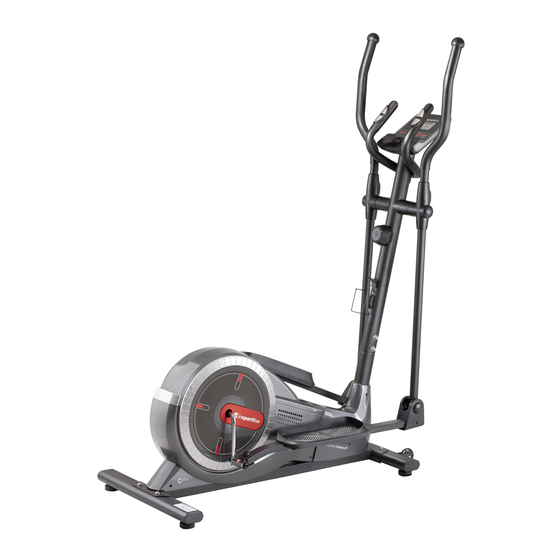
- Page 1 USER MANUAL – EN IN 20106 Elliptical Trainer inSPORTline Hodore ET...
-
Page 2: Table Of Contents
CONTENTS SAFETY INSTRUCTIONS ........................3 IMPORTANT NOTES ..........................3 PARTS LIST ............................5 DIAGRAM ..............................8 ASSEMBLY ............................10 CONSOLE ............................. 15 TROUBLESHOOTING .......................... 16 USE OF ELEPTICAL TRAINER ......................16 THE WARM UP PHASE ........................16 MAINTENANCE ............................ 17 ENVIRONMENT PROTECTION ...................... -
Page 3: Safety Instructions
SAFETY INSTRUCTIONS • To ensure the best safety of the exerciser, regularly check it on damages and worn parts. • If you pass on this exerciser to another person or if you allow another person to use it, make sure that that person is familiar with the content and instructions in these instructions. •... - Page 4 • Be sure to set up the exerciser in a dry and even place and always protect it from humidity. If you wish to protect the place particularly against pressure points, contamination, etc., it is recommended to put a suitable, non-slip mat under the exerciser. •...
-
Page 5: Parts List
PARTS LIST Name Name Main frame Screw M8x20 Spring washer Ø8 Middle post Big washer Ø25xØ8x2 Left handlebar bar D washer Ø38x3 Left footrest bar Sleeve Ø38, Ø32, Ø19, Ø14 Right handlebar bar Plastic sleeve Ø60x88 Right footrest bar Footrest bar cover – A Front stabilizer Footrest bar cover –... - Page 6 Stabilizing feet M10x30 Nut M6 Sensor cable 1600 Freewheel holder Bottle holder Screw M8x20 Screw ST4.8x15 Pulley Washer Ø6xØ12 Nut 7/8“ Washer II Ø23xØ34.5x2.5 Screw M6x10 Nut 7/8“ Screw with eyelet M8X85 Bearings Screw ST4.2x15 Bearing sleeve Left cover Bearing nut 7/8“ Right cover Washer I Ø24xØ40x3.0 Left chain cover...
- Page 7 TOOLS Allen key S6 – 1 pcs Allen key S8 – 1 pcs Hex wrench – 1 pcs Hex wrench S10, S13, S14, S15 – 1 pcs...
-
Page 8: Diagram
DIAGRAM... -
Page 10: Assembly
ASSEMBLY STEP 1 Attach the stabilizing feet (71) to the front and rear stabilizer (7, 8). STEP 2 Remove the two screws (19), the two washers (69) from the front stabilizer (7). Remove the two screws (19), the two washers (69) from the rear stabilizer (8). Attach the front stabilizer (7) to the main frame (1) using the two screws (19), the two washers (69) that you removed. - Page 11 Remove the washer (23) and bolt (24) from the hand screw to adjust the load (21). Pull the cable from the hand screw to adjust the load (21) to the load conditioning cable (22) as shown in Fig. A. Pull and hook the cable as shown in fig. B. Attach the hand screw (21) to the front post (2) using the washer (23) and screw (24) that you removed.
- Page 13 STEP 5 Attach the left and right handles (9, 10) to the left and right handles of the handle (3, 5) using the four screws (31), four washers (32) and four nuts (33). STEP 6 Remove the two screws (29) from the left handlebar (3). Attach the covers (27, 28) to the left handlebar (3) with the two screws (29).
- Page 14 STEP 7 Remove the two screws (19), the two washers (20) from the middle post (2). Pass the pulse cable (14) from the handles (11) to the middle post (2) and pass through the middle post (2). Attach the handles (11) to the middle post (2) using the two screws (19) and two nuts (20). Remove the screws (17) from the back of the bracket (16).
-
Page 15: Console
CONSOLE BUTTONS MODE Button to confirm selection Set time, distance, calories and pulse. RESET Reset time, distance, calories and pulse. FUNCTIONS SCAN Press the MODE button until SCAN appears. All functions are displayed in cycle: time, speed, distance will be displayed. TIME The exercise time is displayed Press the MODE button until TIME is displayed and set the training... -
Page 16: Troubleshooting
TROUBLESHOOTING Elliptical is not stable Level the elliptical with the leveling feet The console does not display data Check cable condition and connection Check the battery condition Replace the batteries Console doesn't measure heart rate Make sure the cables are properly connected Always hold both sensors Too much pressure on the pulse measurement plates. -
Page 17: Maintenance
Inside upper thigh Sit on the floor and place your feet together. Knees are pointed outwards. Pull your feet as close as possible to your groin. Press your knees carefully downwards. Keep this position for 30-40 seconds if possible. Calves and Achilles tendon Lean against a wall with your left leg in front of the right one and your arms forward. - Page 18 These Conditions of Warranty and Warranty Claims are an integral part of every Purchase Agreement made between the Seller and the Buyer. All Warranty Conditions are valid and binding, unless otherwise specified in the Purchase Agreement, in the Amendment to this Contract or in another written agreement.
- Page 19 26847264 VAT ID: CZ26847264 Phone: +420 556 300 970 E-mail: eshop@insportline.cz reklamace@insportline.cz servis@insportline.cz Web: www.inSPORTline.cz inSPORTline s.r.o. Headquaters, warranty & service center: Električná 6471, Trenčín 911 01, SK CRN: 36311723 VAT ID: SK2020177082 Phone: +421(0)326 526 701 E-mail: objednavky@insportline.cz reklamacie@insportline.cz servis@insportline.cz...
Need help?
Do you have a question about the Hodore ET and is the answer not in the manual?
Questions and answers