Table of Contents
Advertisement
Quick Links
Advertisement
Table of Contents

Related Manuals for Insportline Forsan IN 16185


Summary of Contents for Insportline Forsan IN 16185
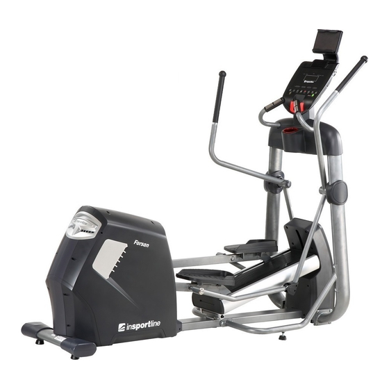
- Page 1 USER MANUAL – EN IN 16185 Elliptical Trainer inSPORTline Forsan...
-
Page 2: Table Of Contents
CONTENTS INTRODUCTION ............................. 3 SAFETY PRECAUTIONS ........................3 EXPLODED DRAWINGS ........................4 PARTS LIST ............................6 PRODUCT DESCRIPTION ........................9 TECHNICAL PARAMETERS ........................ 10 HARDWARE LIST ..........................10 ASSEMBLY MATERIAL LIST ........................ 11 ASSEMBLY INSTRUCTIONS ....................... 13 COMPUTER ............................17 KEY FUNCTIONS .......................... -
Page 3: Introduction
INTRODUCTION Thank you for purchasing this product. To use it properly and safely, read the entire manual and observe all warnings and recommendations. SAFETY PRECAUTIONS • WARNING! This product has been designed to offer the maximum safety. Nevertheless, certain precaution should be kept while using it. Read the whole manual before first using and retain it for future reference. -
Page 4: Exploded Drawings
EXPLODED DRAWINGS... -
Page 6: Parts List
PARTS LIST Description Specification Qty. Front main frame Upright post Front left supporting tube Front right supporting tube Left oscillating bar Right oscillating bar Side pull rod Console I-Pad holder Optional Communication wire L-2100 mm Communication wire L-500 mm Handle pulse wire L-900 mm Wire Computer wire... - Page 7 Side cover for aluminium track Aluminium track Upper aluminium track cover Hex nut Foot pad Allen CKS full-thread screw M10x15 Aluminium track seat Allen CKS full-thread screw M8x20 Ø16x170.4 Rotating axis Ø32x Ø16x12.7 Powder set Rear aluminium track cover Fuse seat Philips CKS self-tapping screw ST3x10 Power cord...
- Page 8 Rod end joint bearing SA12-TK Hex nut M12xP1.75 Allen CKS full thread screw M8x20 Ø42x4.6 Screw cover Deep groove ball bearing 6003-ZZ Ø76x24 Roller Allen CKS full thread screw M6x12 Pedal L Left treadle group Allen CKS half thread screw M10x65x15 Ø20xØ10x8 Powder set...
-
Page 9: Product Description
Ø38xØ32.2x15 Sleeve Ball head tube plug Oscillating bar cover (1) Oscillating bar cover (2) Magnetic induction block Allen CKS half thread screw M10x60x20 Brake line L-2200 mm Magnetic sensor L-2200 mm Power wire L-450 mm (black) Power wire L-450 mm (red) Power cord Controller Allen CKS half thread screw... -
Page 10: Technical Parameters
TECHNICAL PARAMETERS Model No. Dimensions (unfolded) 2150x770x1900 mm Max. loading 150 kg Ratio 12.5 EMS (two-way), ø265/12 kg Flywheel Resistance 1-20 Stride length 500x220 NOTE: The producer reserves the right to change this product without prior notice. HARDWARE LIST Description Specification Qty. -
Page 11: Assembly Material List
Ø8.5xR25xt2.0 Arc-shaped washer Allen CKS full-thread screw M8x20 Ø8.5xØ20xt1.5 Flat washer Ø8.2xØ25xt2.0 Flat washer Ø9.4xØ23.5-M6 Allen CKS hollow thread screw Philips CKS self-tapping screw ST4x16 Allen CKS full-thread screw M6x15 Ø6 Flat washer Philips CKS self-tapping screw ST4x16 (optional) TOOLS: Description Specification Qty. -
Page 12: Wire
I-Pad holder Optional Communication wire L-2100 mm Communication wire L-500 mm Handle pulse wire L-900 mm Wire Computer wire Ø56x16.5 Oscillating bar cover (3) Lower oscillating bar cover L 96x91x26 Lower oscillating bar cover R 96x91x29 Allen CKS full-thread screw M10x20 Ø10 Spring washer... -
Page 13: Assembly Instructions
ASSEMBLY INSTRUCTIONS STEP 1 • Attach the upright post (2) to the front main frame (1) and secure with two flat washers (20), spring washers (19) and allen CKS full-thread screws (18) on both sides. Don’t tighten too firmly. • Take care of the communication wire before assembling the upright post (2). - Page 14 • Tighten all screws and bolts firmly. • Lift up the main frame and join the communication wires (10 and 11) and put them inside the front main frame (1). • To do this step, at least two adult people are necessary as the help for safe and proper assembly.
- Page 15 STEP 5 • Attach the side pull rod (7) to the left oscillating bar (5) with one allen CKS hollow thread screw (27) and tighten it well. • Cover the left oscillating bar (5) with oscillating bar cover 1 (16) and oscillating bar cover 2 (17).
- Page 16 STEP 8 • Lock the I-pad holder (9) on the console (8) using four Philips CKS self-tapping screws (28). • This step is necessary only for product with an I-Pad.
-
Page 17: Computer
COMPUTER KEY FUNCTIONS • START/STOP To start or stop exercising. RESET 1. Push it in the PAUSE mode to return to the IDLE mode. 2. Push and hold it for 5 seconds to restart this computer. 3. Push it while setting in the parameters to go back to previous item. MODE 1. -
Page 18: Program Operations
PROGRAM OPERATIONS Insert the adapter plug into the power socket and connect power. Turn the power on. You can hear one long “bee” sound during the first boot screen. All icons that can be used will display for 2 seconds at the same time. -
Page 19: Recovery Mode
“TESTING”. If the heartbeat will be detected within 10 seconds, follows counting down of 25 seconds. The TIME window shows 0:25 and counts down. The PULSE window displays the heart rate value. The MW window displays the BODY FAT. After counting down over, the DM will show the body fat percentage. After 10 seconds or after pushing the BODY FAT key, it will return to the status before entering the BODY FAT. -
Page 20: Warm-Up/Stretching Exercises
• Always wear appropriate sports clothes and sports shoes. Avoid too loose dress that could be easily caught in the machine. WARM-UP/STRETCHING EXERCISES Each proper exercising should start with a warm-up phase and end with a cooling down phase. The warm-up phase should prepare your body for strenuous workout and the cool-down phase should protect your muscles from pain. -
Page 21: Terms And Conditions Of Warranty, Warranty Claims
TERMS AND CONDITIONS OF WARRANTY, WARRANTY CLAIMS General Conditions of Warranty and Definition of Terms All Warranty Conditions stated hereunder determine Warranty Coverage and Warranty Claim Procedure. Conditions of Warranty and Warranty Claims are governed by Act No. 40/1964 Coll. Civil Code, Act No. - Page 22 VAT ID: CZ26847264 Phone: +420 556 300 970 E-mail: eshop@insportline.cz reklamace@insportline.cz servis@insportline.cz Web: www.insportline.cz INSPORTLINE s.r.o. Headquarters, Warranty & Service centre: Elektricna 6471, 911 01 Trencin, Slovakia CRN: 36311723 VAT ID: SK2020177082 Phone: +421(0)326 526 701 E-mail: objednavky@insportline.sk reklamacie@insportline.sk servis@insportline.sk Web: www.insportline.sk...
Need help?
Do you have a question about the Forsan IN 16185 and is the answer not in the manual?
Questions and answers