Advertisement
Quick Links
Advertisement

Related Manuals for Insportline Caracas IN 4388


Summary of Contents for Insportline Caracas IN 4388
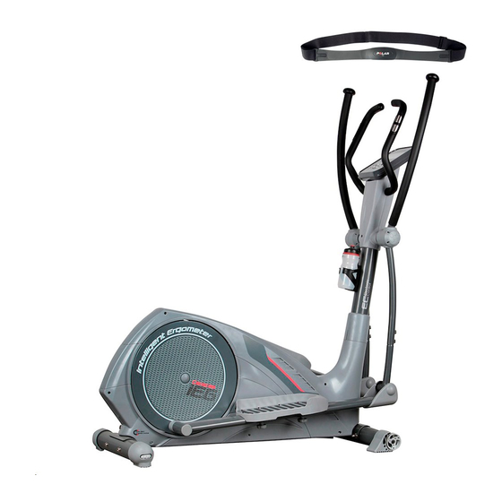
- Page 1 User Manual - EN IN 4388 inSPORTline Elliptical Bike Caracas (KH-831C2)
- Page 2 Safety Instructions To ensure the best safety of the exerciser, regularly check it on damages and worn parts. If you pass on this exerciser to another person or if you allow another person to use it, make sure that that person is familiar with the content and instructions in these instructions.
- Page 3 Important Notes Assemble the exerciser as per assembly instructions and be sure to only use the structural parts provided with the exerciser and designed for it. Prior to the assembly, make sure the content of the delivery is complete by referring to the parts list of the assembly and operating instructions. Be sure to set up the exerciser in a dry and even place and always protect it from humidity.
-
Page 4: Exploded Drawing
EXPLODED DRAWING 7 18 47 84 23 85 86 87 48 93 94 56 84 47 16 70... -
Page 5: Part List
PART LIST Q’TY Q’TY Description Description Main frame Pedal axle cover D46x35 Front stabilizer Round end cap D45*15 D76x1.5Tx480L Inner allen bolt Left crank welding sets M8*1.25*95L Adjustment foot cap Right crank welding sets D76*86 Left moveable foot cap Round cross screw D76*120L ST4.2x1.4x20L Right moveable foot... - Page 6 Cross screw Spring D1.0*55L ST4x1.41x10.L Upper left foot cap Left movable handlebar 80*55*87 Anti-loose nut Right movable handlebar M10*1.25*10T Foam for moving handlebar Pin D6*26.5*7.7 D30x3Tx680L C ring Foam for fixed handlebar D22.5*D18.5*1.2T D23x5Tx530L,HDR Adapter OUTPUT: Mushroom cap D1 1/4"*45L Tension cable Extension spring D1.5x800L...
- Page 7 Front pedal axle Nut M5*0.8*5T D15.83*63.2L Fixing plate for idle Bearing #2203-2RS wheel Flat washer C ring S-40 D28*D8.5*3T Left fixed handlebar Plastic cover D3*30L Right fixed handlebar Fixing nut V Flat washer Sensor cable 1050L D14xD6.5x0.8T Left protective cover Electrical cable 1000L Cross screw Right protective cover...
- Page 8 CHECK LIST & D14*D6.5*0.8T M8*1.25*100L D22*D8.5*1.5T ST4*15L D15.4*D8.2*2T M8*1.25*8T M8*1.25*20L M6*1*45L...
- Page 9 STEP 1 (x4) M8*1.25*95L D22*D8.5*1.5T D22*D8.5*1.5T D15.4*D8.2*2T M8*1.25*15L Step-1 1) Assemble the front stabilizer (2) and rear stabilizer (19) onto the main frame (1) by using the Allen bolt (3), the curved washer (6), the spring washer (7) and the domed nut (8). 2) Adjust the proper height by turning the wheel of rear foot cap (4).
- Page 10 STEP 2 (x4) D14*D6.5*0.8T D40*M6*12 Step-2 1) Assemble the left and right pedal (21L&21R) on the pedal supporting post (11) by using the square neck bolt (20), flat washer (73) and knob (77) like fig.(a & b). 2) 3 optional positions for the pedals like fig. (c).
- Page 11 STEP 3 (x8) M8*1.25*20L D15.4*D8.2*2T D22*D8.5*1.5T Step-3 1) Suggest assembling this step by two persons. 2) Lift up the upper protective cover (49) like fig. (b), connect computer cable (29 & 30) like fig. (c), 3) Insert the handlebar post (10) on the main frame and tighten it like fig. (e) by using the curved washer (6), the spring washer (7) and the Allen bolt (9).
- Page 12 STEP 4 (x4) M5*10L Step-4 1) Connect the computer cable (29) with the computer (64), and then fix the computer (64) on the front post (10) by using the screws (76). 2) Plug the adaptor and test the chest belt(103).
- Page 13 STEP 5 (x2) M8*1.25*100L D22*D8.5*1.5T D22*D8.5*1.5T D15.4*D8.2*2T M8*1.25*8T Step-5 Assemble the left and right fixed handlebar (72L &72R) on the front post (10) by using the Allen bolt (17), the curved washer (6), the spring washer (7) and the nylon nut (18). Connect the pulse cable (65) with computer (64)
- Page 14 STEP 6 (x2) M5*15L (x2) ST4*15L (x2) M5*0.8*10L Step-6 1) Assemble the rear computer bracket (67) and front computer bracket (68) on the front post (10) by using the cross screw (63) and the round cross screw (90). 2) Assemble the bottle holder (102) on the front post (10) use cross bolt (101).Then put the water bottle (100) into the bottle holder (102).
-
Page 15: Button Functions
INSTRUCTION MANUAL OF SM8900-71 【BUTTON FUNCTIONS】 To make upward adjustment to each function data or increase training resistance. DOWN To make downward adjustment to each function data or decrease training resistance. MODE To confirm all setting. STAR/STOP To start or stop workout. RESET To reset current setting and have the monitor switch to initial training mode for selection. -
Page 16: Operating Procedure
【OPERATING PROCEDURE】 Power on: 1. Please connect power adaptor to DC JACK, and console will power on with beep sound for 2 seconds and LCD display all segments. 2. Console will show “SELECT USER”, user may press mode to enter into user selection mode. Use joggle wheel to select U1 to U4 and press MODE for confirmation. - Page 17 Workout in MANUAL mode: In standby mode, select MANUAL and press MODE to enter. Quick start: User may press START/STOP to start training in MANUAL, all exercise values will start counting up from zero. After enter into MANUAL mode, user may set up TIME DISTANCE CALORIES PULSE RESISTANCE LEVEL by follow flashing windows, and press START/STOP to start workout.
- Page 18 Workout in PROGRAM mode: In standby mode, select PROGRAM and press MODE to enter. User may turn joggle wheel up or down to select preferred program from 1 to 12, and press MODE to confirm. Program profile will flashing, user may turn up or down to adjust profile’s resistance level. TIME is fixed in 20:00, which is not adjustable.
- Page 19 Workout in User program mode: In standby mode, select USER PRO and press MODE to enter. User may create his/her own preferred profile by turning UP and DOWN to set up resistance level of each row, and press MODE to confirm. User may hold on pressing MODE button to finish setting. Time is fixed in 20:00, which is not adjustable.
- Page 20 Workout in H.R.C. mode: In standby mode, select H.R.C. and press MODE to enter. AGE 25 is flashing after enter H.R.C. mode, you may set your age by turning UP/DOWN button and press MODE. The monitor will calculate preset heart rate value automatically according to your age setting.
- Page 21 Workout in WATT constant mode: In standby mode, select WATT and press MODE to enter. The preset watt value 120 is flashing on screen in WATT setting mode, select UP/DOWN/ENTER to set target value from 10 to 350. Pressing START button to start training. After start, Level is adjusted according to RPM to reach the setting WATT.
- Page 22 1. Press BODY FAT button, and hold on handgrip to start body fat testing. 2. The symbol "- - - - - - - - " will display while testing period in 8 seconds. After 8 seconds, you will see the BODY FAT advice in percentage and BMI and the fat advice in different symbol. 3.
- Page 23 RECOVERY: After exercising for a period of time, keep holding on handgrips and press “RECOVERY” button. All function display will stop except “TIME” starts counting down from 00:60 to 00:00. Screen will display your heart rate recovery status with the F1,F2….to F6. F1 is the best, F6 is the worst.
- Page 24 NOTE: 1. This computer require 9V, 1A or 9V, 0.5A adaptor. 2. When user stop pedaling for 4 minutes, computer will enter into power save mode, all setting and exercise data will stored until user start exercise again. 3. When computer act abnormal, please plug out the adaptor and plug in again. 4.
Need help?
Do you have a question about the Caracas IN 4388 and is the answer not in the manual?
Questions and answers