Table of Contents
Advertisement
Quick Links
User's Guide
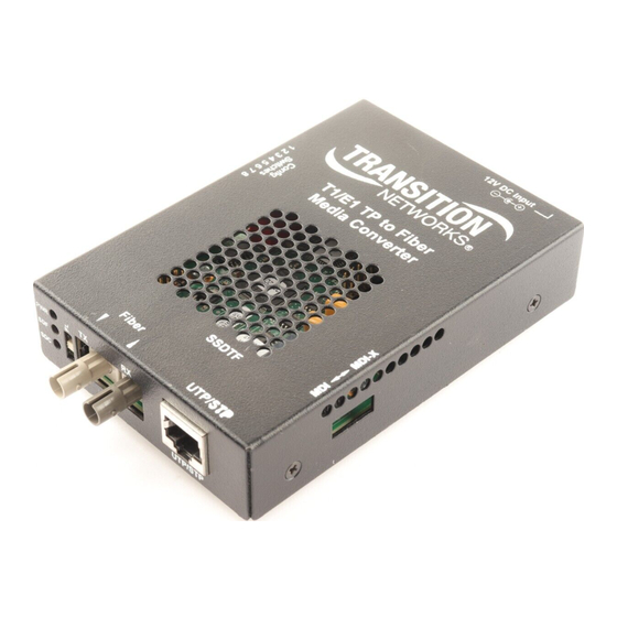
SSDTF10xx-10x
Stand-Alone Media Converter
• T1 / E1 with Remote Management
• Copper to Fiber
Transition Networks SSDTF10xx-10x series media
converters encode and decode T1 or E1 twisted-pair
copper signals over fiber optic cable to extend the
distance and transmission reliability of high-speed
T1 or E1 data traffic. The device is framing independent (as ESF vs. D4) and supports all
common line codes (e.g., AMI, B8ZS, HDB3).
The SSDTF10xx-10x is designed to be installed in pairs. For example, install one
SSDTF1011-105 as the "local" media converter and another SSDTF1011-105 as the
"remote" media converter.
Part Number
Port One - Copper
SSDTF1011-105
RJ-45
1.5 km (5,000 feet)*
SSDTF1012-105
RJ-45
1.5 km (5,000 feet)*
SSDTF1013-105
RJ-45
1.5 km (5,000 feet)*
SSDTF1014-105
RJ-45
1.5 km (5,000 feet)*
SSDTF1015-105
RJ-45
1.5 km (5,000 feet)*
SSDTF1016-105
RJ-45
1.5 km (5,000 feet)*
SSDTF1017-105
RJ-45
1.5 km (5,000 feet)*
SSDTF1018-105
RJ-45
1.5 km (5,000 feet)*
SSDTF1022-105
RJ-45
1.5 km (5,000 feet)*
SSDTF1025-105
RJ-45
1.5 km (5,000 feet)*
SSDTF1027-105
RJ-45
1.5 km (5,000 feet)*
* Typical maximum cable distance. (Actual
distance is dependent upon the physical
characteristics of the network.)
Note: The SSDTF10xx-10x requires a CSU
between the converter and the Public
Telephone Network.
Port Two - Duplex Fiber-Optic
ST, 850 nm multimode
2 km (1.2 miles)*
ST, 1310 nm single mode
8 km (4.8 miles)*
SC, 850 nm multimode
2 km (1.2 miles)*
SC, 1310 nm single mode
20 km (12.4 miles)*
SC, 1310 nm single mode
40 km (24.8 miles)*
SC, 1310 nm single mode
60 km (37.3 miles)*
SC, 1550 nm single mode
80 km (49.7 miles)*
MT-RJ, 1300 nm multimode
2 km (1.2 miles)*
ST, 1310 nm single mode
15 km (9.3 miles)*
MT-RJ, 1310 nm single mode
20 km (12.4 miles)*
ST, 1300 nm multimode
5 km (3.1 miles)*
Installation . . . . . . . . . . . . . . . . . .3
Operation . . . . . . . . . . . . . . . . . . .9
Cable Specifications . . . . . . . . . .10
Technical Specifications . . . . . . .12
Troubleshooting . . . . . . . . . . . . .13
Compliance Information . . . . . . .16
Advertisement
Table of Contents

Subscribe to Our Youtube Channel
Related Manuals for Transition Networks SSDTF1011-105


Summary of Contents for Transition Networks SSDTF1011-105
- Page 1 T1 or E1 data traffic. The device is framing independent (as ESF vs. D4) and supports all common line codes (e.g., AMI, B8ZS, HDB3). The SSDTF10xx-10x is designed to be installed in pairs. For example, install one SSDTF1011-105 as the “local” media converter and another SSDTF1011-105 as the “remote” media converter. Part Number...
-
Page 2: Installation
SSDTF10xx-10x Installation Part Number Port One - Copper Port Two - Single Fiber Optic SSDTF1029-105 ** RJ-45 SC, 1310 mn (TX)/1550 nm (RX) 1.5 km (5,000 feet)* single mode, 20 km (12.4 miles)* CAUTION: Wear a grounding device and observe electrostatic discharge precautions when setting the jumper and switches. - Page 3 SSDTF10xx-10x Installation Installation -- Continued -- Continued Set the loop-back switch Switch 1, Copper -- transmit all ones UP - Disables the transmit all ones Hardware mode: function on the copper interface. The loop-back switch is located on the front panel of the media converter and is used for installation and network debugging procedures.
- Page 4 SSDTF10xx-10x Installation Installation -- Continued -- Continued Settings for T1 configuration T1/short-haul signal (right switch set, SW 1) T1/long-haul signal Use switches 3 and 4 on the left switch set to select T1/short-haul signal (see the drawing below). Use switches 3 and 4 on the left switch set to select T1/long-haul signal (see the drawing below).
-
Page 5: Operation
Connect the RJ-45 connector at the other end of the cable to the RJ-45 port on For DC power, consult the user’s guide for the Transition Networks SPS1872-xx the other device (switch, workstation, etc.). DC external power supply for powering the media converter. -
Page 6: Cable Specifications
Fiber Optic Receiver Sensitivity: min: -32.5 dBm max: -14.0 dBm Multimode fiber (optional): 100/140, 85/140, 50/125 μm Link Budget: 13.5 dB SSDTF1011-105 850 nm multimode SSDTF1029-105 1310 nm (TX)/1550 nm (RX) simplex Fiber Optic Transmitter Power: min: -19.0 dBm max: -14.0 dBm Fiber-optic Transmitter Power: min: -13.0 dBm... -
Page 7: Technical Specifications
SSDTF10xx-10x Technical Specifications Troubleshooting For use with Transition Networks Model SSDTF10xx-10x or equivalent If the media converter fails, isolate and correct the failure by determining the answers to the following questions and then taking the indicated action: Standards: Emissions: CISPR A; Telecordia TR-NWT-001089 (designed to meet;... - Page 8 00-1-952-941-7600 then use a bit error test unit to run a bit error test. Transition now Chat live via the Web with Transition Networks Technical Support. Log onto www.transition.com and click the Transition Now link. Web-based seminars Transition Networks provides seminars via live web-based training.
-
Page 9: Compliance Information
© 2002-2005 Transition Networks. All rights reserved. No part of this work may be reproduced or used in any form or by any means - graphic, electronic, or mechanical - without written permission from Transition Networks. 33246.F Printed in the U.S.A.
Need help?
Do you have a question about the SSDTF1011-105 and is the answer not in the manual?
Questions and answers