SEW-Eurodrive MOVIMOT MM D Series Manual
Drive system for decentralized installation, profinet io interfaces, field distributors.
Hide thumbs
Also See for MOVIMOT MM D Series:
- Operating instructions manual (132 pages) ,
- Compact operating instructions (80 pages) ,
- Manual (56 pages)

Subscribe to Our Youtube Channel
Related Manuals for SEW-Eurodrive MOVIMOT MM D Series


Summary of Contents for SEW-Eurodrive MOVIMOT MM D Series
- Page 1 *22870857_1216* Drive Technology \ Drive Automation \ System Integration \ Services Manual Drive System for Decentralized Installation PROFINET IO Interfaces, Field Distributors Edition 12/2016 22870857/EN...
- Page 2 SEW-EURODRIVE—Driving the world...
-
Page 3: Table Of Contents
Contents Contents Valid components........................ 6 General information........................ 7 About this documentation .................... 7 Structure of the safety notes ................... 7 Rights to claim under limited warranty ................ 9 Exclusion of liability...................... 9 Other applicable documentation .................. 9 Copyright notice ...................... 9 Product names and trademarks.................. 9 Safety notes .......................... 10 Preliminary information .................... 10 Operator's duties...................... 10 Target group ......................... 10... - Page 4 PROFINET IO configuration with topology detection.......... 100 Parameterization via PROFIdrive dataset 47 .............. 107 Introduction PROFINET data sets ................ 107 Properties of the SEW-EURODRIVE PROFINET devices ......... 108 Structure of the PROFINET parameter channel ............ 109 Reading or writing the parameterization via dataset 47.......... 127 Function..........................
- Page 5 Contents Technical data........................ 174 15.1 Technical data MFE52B PROFINET IO interface............ 174 15.2 Technical data for field distributors ................ 176 Declaration of conformity .................... 179 Address list ........................... 181 Index ............................ 192 Manual – PROFINET IO Interfaces, Field Distributors...
-
Page 6: Valid Components
Valid components Valid components This manual applies to the following PROFINET IO products: Connection module ..Z.1. with fieldbus interface 4 x I / 2 x IO (M12) PROFINET IO MFE52B/Z21D Field distributor ..Z.3. with fieldbus interface 4 x I / 2 x IO (M12) PROFINET IO MFE52B/Z23D Field distributor ..Z.6. -
Page 7: General Information
General information About this documentation General information About this documentation This documentation is an integral part of the product. The documentation is written for all employees who assemble, install, start up, and service this product. Make sure this documentation is accessible and legible. Ensure that persons respons- ible for the machinery and its operation as well as persons who work on the product independently have read through the documentation carefully and understood it. - Page 8 General information Structure of the safety notes Meaning of the hazard symbols The hazard symbols in the safety notes have the following meaning: Hazard symbol Meaning General hazard Warning of dangerous electrical voltage Warning of hot surfaces Warning of risk of crushing Warning of suspended load Warning of automatic restart 2.2.3...
-
Page 9: Rights To Claim Under Limited Warranty
General information Rights to claim under limited warranty Rights to claim under limited warranty Read the information in this documentation. This is essential for fault-free operation and fulfillment of any rights to claim under limited warranty. Read the documentation before you start working with the product. Exclusion of liability Read the information in this documentation, otherwise safe operation is impossible. -
Page 10: Safety Notes
Safety notes Preliminary information Safety notes Preliminary information The following general safety notes have the purpose to avoid injury and damage to property. They primarily apply to the use of products described in this documentation. If you use additional components also observe the relevant warning and safety notes. Operator's duties Make sure that the basic safety notes are read and observed. -
Page 11: Designated Use
Safety notes Designated use Specialist for elec- Any electronic work may only be performed by adequately skilled persons (electric- trotechnical work ally). Qualified electricians in the context of this documentation are persons familiar with electrical installation, startup, troubleshooting and servicing of the product who possess the following qualifications: •... -
Page 12: Functional Safety Technology
Safety notes Functional safety technology Functional safety technology The product must not perform any safety functions without a higher-level safety sys- tem, unless explicitly allowed by the documentation. Transport Inspect the shipment for damage as soon as you receive the delivery. Inform the ship- ping company immediately about any damage. -
Page 13: Electrical Connection
Safety notes Electrical connection • Above 2000 m asl, the air and creeping distances are only sufficient for over- voltage class II according to EN 60664. If the installation requires overvoltage cat- egory III according to EN 60664 you have to reduce the overvoltages on the sys- tem side from category III to II using additional external overvoltage protection. -
Page 14: Startup/Operation
Safety notes Startup/operation 3.10 Startup/operation Observe the safety notes in the chapters "Startup" and "Operation" in the documenta- tion. Make sure that the present transport protection is removed. Do not deactivate monitoring and protection devices of the machine or system even for a test run. -
Page 15: Device Structure
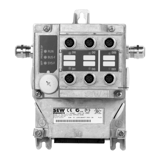
Device structure Fieldbus interface Device structure Fieldbus interface 4.1.1 MFE52 fieldbus interface The following figure depicts the MFE52 fieldbus interface: 9007202575522315 [1] M12 connection sockets for digital inputs/outputs [2] Status LEDs of digital inputs/outputs [3] X12 PROFINET IO connection port 2 [4] X11 PROFINET IO connection port 1 [5] Diagnostic interface (below screw fitting) [6] Diagnostics LEDs... - Page 16 Device structure Fieldbus interface 4.1.3 Device structure of MFZ connection module The following figure shows the MFZ connection module. 9007200390917003 [1] Terminal strip X20 [2] Isolated terminal block for 24 V through-wiring (NOTICE: Do not use for shielding.) [3] M20 cable gland [4] M12 cable gland [5] Grounding terminal The scope of delivery includes 2 EMC cable glands.
-
Page 17: Type Designation Of The Profinet Io Interfaces
Device structure Type designation of the PROFINET IO interfaces Type designation of the PROFINET IO interfaces 4.2.1 Nameplate The following figure gives an example for the nameplate of a fieldbus interface: Ethernetmodul MFE52B P# : 28238761 S# : 0912346 15/16 . -
Page 18: Field Distributor
Device structure Field distributor Field distributor 4.3.1 MF../Z.3., MQ../Z.3. field distributors 9007200390936971 [1] For DeviceNet™: Micro-style connector/M12 connector (X11) [2] 2 x M20 x 1.5 [3] 2 x M25 x 1.5 [4] 2 x M16 x 1.5 (2 EMC cable glands included in the delivery) [5] Terminals for fieldbus connection (X20) [6] Terminals for 24 V connection (X21) [7] Terminals for power supply and PE connection (X1) - Page 19 Device structure Field distributor 4.3.2 MF../Z.6., MQ../Z.6. field distributors [8] [3] [9] 9007200390944651 [1] 6 x M20 x 1.5 (delivery includes 2 EMC cable glands) For DeviceNet™: Micro-style connector/M12 connector (X11) [2] 2 x M25 x 1.5 [3] Connection PE/equipotential bonding ®...
- Page 20 Device structure Field distributor 4.3.3 MF../MM../Z.7., MQ../MM../Z.7. field distributors [10] [11] [12] 9007200391188619 2 x M25 x 1.5 cable glands 5 x M20 x 1.5 cable glands (delivery includes 2 EMC cable glands) For DeviceNet™: Micro-style connector/M12 connector (X11) Connection PE/equipotential bonding Hybrid cable connection;...
- Page 21 Device structure Field distributor 4.3.4 MF../MM../Z.8., MQ../MM../Z.8. field distributors [10] 18014399645961355 6 x M20 x 1.5 cable glands (delivery includes 2 EMC cable glands) For DeviceNet™: Micro-style connector/M12 connector (X11) 2 x M25 x 1.5 cable glands Terminals for power supply and PE connection (X1) Maintenance switch (triple lock, color: black/red) Only with MFPZ28J design: Optional integrated feedback for position of the maintenance switch.
- Page 22 Device structure Field distributor 4.3.5 MF../MM../Z.9. field distributor ® [12] MOVIMOT 1 ® [12] MOVIMOT 2 ® [12] MOVIMOT 3 [11] [10] [3] [2] 18227105419 ® Connection to MOVIMOT inverter Motor power terminals (X4_.) 3 x M25 x 1.5 cable gland (EMC cable glands supplied as an option) Motor control terminals (X6_.) 2 x M25 x 1.5 cable glands 2 x M20 x 1.5 cable glands...
-
Page 23: Type Designation Of The Profinet Io Field Distributors
Device structure Type designation of the PROFINET IO field distributors Type designation of the PROFINET IO field distributors 4.4.1 Field distributor nameplate The following figure shows an example of the nameplate of the MFP../MM../Z.8 field distributor: N2936 LISTED U = 3x380 . . . 500V AC IND.CONT.EQ. - Page 24 Device structure Type designation of the PROFINET IO field distributors 4.4.3 Type designation MF../Z.6. The following table shows the type designation for MF../Z.6. field distributors as an ex- ample: Fieldbus interface MFP../MQP.. = PROFIBUS ® MFE.. = PROFINET IO, EtherNet/IP™ or EtherCAT MFD../MQD..
- Page 25 Device structure Type designation of the PROFINET IO field distributors 4.4.4 Type designation MF../MM../Z.7. The following table shows the type designation for MF../MM../Z.7. field distributors as an example: Fieldbus interface MFP../MQP.. = PROFIBUS ® MFE.. = PROFINET IO, EtherNet/IP™ or EtherCAT MFD../MQD..
- Page 26 Device structure Type designation of the PROFINET IO field distributors 4.4.5 Type designation MF../MM..Z.8. The following table shows the type designation for MF../MM../Z.8. field distributors as an example: Fieldbus interface MFP../MQP.. = PROFIBUS ® MFE.. = PROFINET IO, EtherNet/IP™ or EtherCAT MFD../MQD..
- Page 27 Device structure Type designation of the PROFINET IO field distributors 4.4.6 Type designation MF../MM..Z.9. The following table shows the type designation for MF../MM../Z.9. field distributors as an example: Fieldbus interface MFE.. = PROFINET IO ® MM15D MOVIMOT inverter -503-00 No designation = without inverter ®...
-
Page 28: Mechanical Installation
Mechanical installation Installation instructions Mechanical installation Installation instructions INFORMATION On delivery, field distributors are equipped with transportation protection covering the plug connector of the outgoing motor circuit (hybrid cable). This only guarantees the degree of protection IP40. To obtain the specified degree of protection, remove the transport protection and plug on the appropriate mating con- nector. -
Page 29: Tightening Torques
Mechanical installation Tightening torques Tightening torques ® 5.2.1 MOVIMOT inverter 9007200393241611 ® Tighten the screws for fastening MOVIMOT using 3.0 Nm in diametrically opposite sequence. 5.2.2 Fieldbus interface / connection box cover 9007200393245323 Tighten the screws on the fieldbus interfaces or connection box cover using 2.5 Nm in diametrically opposite sequence. - Page 30 Mechanical installation Tightening torques 5.2.3 Screw plugs 9007200393250059 Tighten the blanking plugs and the screw plugs of potentiometer f1, and of connection X50, if applicable, using 2.5 Nm. 5.2.4 EMC cable glands 1138616971 Tighten EMC cable glands supplied by SEW‑EURODRIVE using the following torque ratings: Screw fitting Tightening torque...
-
Page 31: Fieldbus Interfaces Mf
Mechanical installation Fieldbus interfaces MF../MQ.. Fieldbus interfaces MF../MQ.. MF../MQ.. fieldbus interfaces can be installed as follows: ® • Installation on MOVIMOT connection box • Installation in the field (= mounting close to the motor) ® 5.3.1 Installation on MOVIMOT connection box 1. - Page 32 Mechanical installation Fieldbus interfaces MF../MQ.. ® 2. Mount the fieldbus interface to the MOVIMOT connection box, according to the following figure. . . / M 3.0 – 3,5 Nm 18014399648145931 Manual – PROFINET IO Interfaces, Field Distributors...
- Page 33 Mechanical installation Fieldbus interfaces MF../MQ.. 5.3.2 Installation in the field The following figure shows the installation of an MF../MQ.. fieldbus interface close to the motor: Z ../ M . . / M 1138749323 [1] Length of screws min. 40 mm Manual –...
-
Page 34: Field Distributor
Mechanical installation Field distributor Field distributor 5.4.1 Installation of MF../Z.3., MQ../Z.3. field distributors The following figure shows the mounting dimensions for ..Z.3. field distributors: 9007200393500299 5.4.2 Installation of MF../Z.6., MQ../Z.6. field distributors The following figure shows the mounting dimensions for ..Z.6. field distributors: 18014399648277003 Manual –... - Page 35 Mechanical installation Field distributor 5.4.3 Installation of MF../MM../Z.7., MQ../MM../Z.7. field distributors The following figure shows the mounting dimensions for ..Z.7. field distributors: 18014399648313483 5.4.4 Installation of MF../MM../Z.8., MQ../MM../Z.8. field distributors (Size 1) The following figure shows the mounting dimensions for ..Z.8. field distributors (Size 1): 18014399648325131 Manual –...
- Page 36 Mechanical installation Field distributor 5.4.5 Installation of MF../MM../Z.8., MQ../MM../Z.8. field distributors (Size 2) The following figure shows the mounting dimensions for ..Z.8. field distributors (Size 2): 18014399648338187 Manual – PROFINET IO Interfaces, Field Distributors...
- Page 37 Mechanical installation Field distributor 5.4.6 Installation of MF../MM../Z.9. field distributors The following figure shows the mounting dimensions for ..Z.9. field distributors: 18223713419 Manual – PROFINET IO Interfaces, Field Distributors...
- Page 38 Mechanical installation Field distributor ® Notes on installation of the MOVIMOT inverters at the MFZ29 field distributor WARNING ® Uncontrolled enabling of an unexpected drive by swapping the MOVIMOT invert- ers. Severe or fatal injuries. ® • Install the MOVIMOT inverters based on the set RS485 address according to the following figure: ®...
-
Page 39: Electrical Installation
Electrical installation Installation planning taking EMC aspects into account Electrical installation Installation planning taking EMC aspects into account INFORMATION This drive system is not designed for operation on a public low voltage supply system that supplies residential areas. ® MOVIMOT can cause EMC interference within the permitted limit range according to EN 61800-3. - Page 40 Electrical installation Installation planning taking EMC aspects into account 6.1.4 Cable glands • Select only cable glands with a shield connected over a large area. Observe the notes regarding the selection of the cable glands. 6.1.5 Cable shields • Must have good EMC properties (high screening attenuation). •...
-
Page 41: Installation Instructions For Fieldbus Interfaces, Field Distributors
Electrical installation Installation instructions for fieldbus interfaces, field distributors Installation instructions for fieldbus interfaces, field distributors 6.2.1 Connecting supply system leads ® • The nominal voltage and frequency of the MOVIMOT inverter must correspond to the data for the power supply system. •... - Page 42 Electrical installation Installation instructions for fieldbus interfaces, field distributors 6.2.2 Permitted connection cross section of terminals Power terminals X1, X21 Control terminals X20 (screw terminals) (cage clamp terminals) Connection cross sec- 0.2 mm – 4 mm 0.08 mm – 2.5 mm tion The permitted tightening torque of the power terminals is 0.6 Nm. ®...
- Page 43 Electrical installation Installation instructions for fieldbus interfaces, field distributors 6.2.4 Residual current device WARNING No protection against electric shock if an incorrect type of residual current device is used. Severe or fatal injuries. • Use only universal current sensitive residual current devices of type B for invert- ers.
- Page 44 Electrical installation Installation instructions for fieldbus interfaces, field distributors 6.2.7 Notes on PE connection WARNING Electric shock due to faulty ground connection or faulty equipotential bonding. Severe, fatal injuries • The permitted tightening torque for the retaining screws is 2.0 – 2.4 Nm. •...
- Page 45 Electrical installation Installation instructions for fieldbus interfaces, field distributors 6.2.8 Looping through the DC 24 V supply voltage in the MFZ.1 module terminal box • There are 2 M4 x 12 studs in the connection area of the DC 24 V supply. The studs can be used for looping the DC 24 V supply voltage.
- Page 46 Electrical installation Installation instructions for fieldbus interfaces, field distributors 6.2.9 Additional connection options with MFZ.6, MFZ.7 and MFZ.8 field distributors • The connection part of the DC 24 V supply comprises an X29 terminal block with two M4 x 12 studs and a pluggable X40 terminal. 1141387787 •...
- Page 47 Electrical installation Installation instructions for fieldbus interfaces, field distributors 6.2.10 UL-compliant installation INFORMATION Due to UL requirements, the following chapter is always printed in English independ- ent of the language of the documentation. Field wiring power terminals Observe the following notes for UL-compliant installation: •...
-
Page 48: Connection Of Mfz21 Connection Module With Mfe52 To Movimot
Electrical installation Connection of MFZ21 connection module with MFE52 to MOVIMOT® Connection of MFZ21 connection module with MFE52 to MOVIMOT® ® Connection of MFZ21 connection module with MFE52 to MOVIMOT ® 6.3.1 MFZ21 connection module with PROFINET IO interface MFE52 connected to MOVIMOT (for a configuration with 6 inputs or with 4 inputs/2 outputs) ®... -
Page 49: Connection Of Mfz23 Field Distributor With Mfe52
Electrical installation Connection of MFZ23 field distributor with MFE52 Connection of MFZ23 field distributor with MFE52 6.4.1 MFZ33 connection module with MFE52 PROFINET IO interface and 2 separate DC 24 V circuits (only for a configuration with 4 inputs/2 outputs) MFZ23 4 mm (AWG10) 4 mm (AWG10) 2.5 mm (AWG12) MFE52... - Page 50 Electrical installation Connection of MFZ23 field distributor with MFE52 6.4.2 MFZ33 connection module with MFE52 PROFINET IO interface and 1 shared DC 24 V circuit (for a configuration with 6 inputs or with 4 inputs/2 outputs) MFZ23 4 mm (AWG10) 2.5 mm (AWG12) 4 mm (AWG10) MFE52 1 x DC 24 V...
-
Page 51: Connection Of Mfz26, Mfz27, Mfz28 Field Distributors With Mfe52
Electrical installation Connection of MFZ26, MFZ27, MFZ28 field distributors with MFE52 Connection of MFZ26, MFZ27, MFZ28 field distributors with MFE52 6.5.1 MFZ26, MFZ27, MFZ28 connection modules with PROFINET IO interface MFE52 and 2 separate DC 24 V voltage circuits (only for a configuration with 4 inputs/2 outputs) MFZ26 4 mm (AWG10) MFZ27... - Page 52 Electrical installation Connection of MFZ26, MFZ27, MFZ28 field distributors with MFE52 6.5.2 MFZ26, MFZ27, MFZ28 connection modules with PROFINET IO interface MFE52 and 1 shared DC 24 V voltage circuit (for a configuration with 6 inputs or with 4 inputs/2 outputs) MFZ26 4 mm (AWG10) MFZ27...
-
Page 53: Connection Of Mfz29 Field Distributor With Mfe52
Electrical installation Connection of MFZ29 field distributor with MFE52 Connection of MFZ29 field distributor with MFE52 6.6.1 Terminal positions The following figure shows the position of the terminals and PE connections of the field distributor as an example: 1 2 3 4 5 6 7 8 9 1 2 3 4 5 6 7 8 9 1 2 3 4 5 6 7 8 9 X6_1... - Page 54 Electrical installation Connection of MFZ29 field distributor with MFE52 6.6.2 X1, X20, X21 line terminals, 24 V supply MFZ29 connection module with MFE52 PROFINET IO interface and 2 separate DC 24 V circuits (only for a configuration with 4 inputs/2 outputs) MFZ29 4 mm (AWG10) 2.5 mm (AWG12) 4.0 mm (AWG10)
- Page 55 Electrical installation Connection of MFZ29 field distributor with MFE52 Terminal assignment 24 V distributor terminals Name Direction Function X20 1 24V_C Output 24 V voltage supply for module electronics and sensors jumpered with terminal X21/1 0V24_C 0V24 reference potential for module electronics and sensors jumpered with terminal X21/3 ®...
- Page 56 Electrical installation Connection of MFZ29 field distributor with MFE52 MFZ29 connection module with MFE52 PROFINET IO interface and 1 shared DC 24 V circuit (for a configuration with 6 inputs or with 4 inputs/2 outputs) MFZ29 4 mm (AWG10) 2.5 mm (AWG12) 4.0 mm (AWG10) MFE52 24V_C...
- Page 57 Electrical installation Connection of MFZ29 field distributor with MFE52 Terminal assignment 24 V distributor terminals Name Direction Function X20 1 24V_C Output 24 V voltage supply for module electronics and sensors jumpered with terminal X21/1 0V24_C 0V24 reference potential for module electronics and sensors jumpered with terminal X21/3 ®...
- Page 58 Electrical installation Connection of MFZ29 field distributor with MFE52 Connection variants The MFZ29 field distributor has additional functions for special connections. The fol- lowing chapters describe the additional connections and the resulting functions. Connection variant parallel connection and ready signal via digital input DI4 (option) The following figure shows the parallel connection of the ready signal of the ®...
- Page 59 Electrical installation Connection of MFZ29 field distributor with MFE52 Connection variant feedback maintenance switch (MFZ29J design) The following figure shows the additional connection of the MF29J field distributor for the feedback of the maintenance switch. X6_1 18200674699 [1] The cables labeled with "––" are already wired at the factory. Function With this additional connection, the field distributor delivers the status of the mainten- ance switch to the higher-level controller.
- Page 60 Electrical installation Connection of MFZ29 field distributor with MFE52 Connection variant rapid start/rapid stop via digital output DO0 (option) The following figure shows an example of the additional connection for the simultan- ® eous rapid start and rapid stop of all MOVIMOT drives: X6_1 X6_2...
- Page 61 Electrical installation Connection of MFZ29 field distributor with MFE52 6.6.3 X6_1, X6_2, X6_3 motor 1 – 3 control terminals Motor 1 – 3 control terminals Name Direction Function ® X6_1 24V P Output 24 V voltage supply for TH, L and R of the MOVIMOT inverter X6_2 ®...
-
Page 62: Connection Of The Inputs/Outputs Of The Mfe52 Fieldbus Interface
Electrical installation Connection of the inputs/outputs of the MFE52 fieldbus interface Connection of the inputs/outputs of the MFE52 fieldbus interface The fieldbus interface is connected via terminals or M12 plug connectors. 6.7.1 Connection of inputs/outputs via terminals For fieldbus interfaces with 4 digital inputs and 2 digital inputs/outputs: MFZ.1 MFZ.6 in combination with... - Page 63 Electrical installation Connection of the inputs/outputs of the MFE52 fieldbus interface Terminal assignment Name Direction Function X20 31 DIO4 Input Sensor DI4 switching signal Output Actuator DO0 switching signal GND2 – 0V24 reference potential for sensor DI4 – 0V24 reference potential for actuator DO0 DIO5 Input Sensor DI5 switching signal...
- Page 64 Electrical installation Connection of the inputs/outputs of the MFE52 fieldbus interface 6.7.2 Connection of inputs/outputs via M12 plug connectors For MFE52A/MFE52B fieldbus interfaces with 4 digital inputs and 2 digital inputs/outputs: NOTICE Loss of the guaranteed degree of protection if the screw plugs in the unused M12 connections are not installed or not installed correctly.
- Page 65 Electrical installation Connection of the inputs/outputs of the MFE52 fieldbus interface For MFE52G/MFE52H fieldbus interfaces NOTICE Loss of the guaranteed degree of protection if the screw plugs in the unused M12 connections are not installed or not installed correctly. Damage to the fieldbus interface. •...
-
Page 66: Connection Of Profinet Io
Electrical installation Connection of PROFINET IO Connection of PROFINET IO The following figure shows the connections of the PROFINET IO bus: 9007202600365067 [1] X11, PROFINET IO connection, port 1 [2] X12, PROFINET IO connection, port 2 The following table shows the pin assignment of the PROFINET IO ports X11 and X12: Function PROFINET IO interface... - Page 67 Electrical installation Connection of PROFINET IO 6.8.1 The integrated Ethernet switch You can use the integrated Ethernet switch to achieve line topologies known from the fieldbus technology. Other bus topologies, such as star or tree, are also possible. INFORMATION The number of Industrial Ethernet switches connected in line affects the telegram runtime.
- Page 68 Electrical installation Connection of PROFINET IO 6.8.2 Routing the Ethernet cable NOTICE In case of fluctuations in the ground potential, a compensating current may flow via the bilaterally connected shield that is also connected to the protective earth (PE). Make sure you supply adequate equipotential bonding in accordance with relevant VDE regulations in such a case.
-
Page 69: Hybrid Cable Connection
Electrical installation Hybrid cable connection Hybrid cable connection ® 6.9.1 Hybrid cable between MFZ.3. or MFZ.6. field distributor and MOVIMOT ® The following figure shows the hybrid cable for connecting the MOVIMOT drive part number (01867253). MFZ.3 MFZ.6 9007200401506827 The following table shows the terminal assignment of the hybrid cable in the ®... - Page 70 Electrical installation Hybrid cable connection 6.9.2 Hybrid cable between MFZ.7. or MFZ.8. field distributor and AC motors The following figure shows the hybrid cable for connecting the AC motor part number 01867423. MFZ.8 MFZ.7 9007200402006667 The following table shows the terminal assignment of the hybrid cable in the motor ter- minal box: Terminal assignment Motor terminal...
- Page 71 Electrical installation Hybrid cable connection 6.9.3 Hybrid cable between MFZ.9. field distributor and AC motors The following figure shows the hybrid cable for connecting the AC motor part number 08184380. MFZ.9 18205192331 The following table shows the terminal assignment of the hybrid cable in the motor ter- minal box and in the field distributor: Terminal assignment Motor ter-...
-
Page 72: Pc/Laptop Connection
Electrical installation PC/laptop connection 6.10 PC/laptop connection The fieldbus interfaces have a diagnostic interface (RJ10 plug connector) for startup, parameter setting, and service. The diagnostic interface is located underneath the screw plug of the fieldbus interface. You must remove the screw plug before plugging in the connector into the diagnostic interface. -
Page 73: Wiring Check
Electrical installation Wiring check 6.11 Wiring check INFORMATION For ensuring the isolation and the effectiveness of preventive measures, you have to perform the checks of the valid and applicable standards (e.g. EN 60204-1 or EN 61800-5) after any wiring work for installation, conversion, repair, etc. In order to prevent injury to persons or damage to the plant, check the wiring as de- scribed below before you connect the voltage supply for the first time: •... -
Page 74: Startup
Startup Startup instructions Startup Startup instructions WARNING Risk of crushing due to missing or defective protective covers. Severe or fatal injuries. • Install the protective covers of the plant according to the instructions, see the op- erating instructions of the gear unit. •... - Page 75 Startup Startup instructions INFORMATION • Switch off the DC 24 V voltage supply before removing/installing the fieldbus inter- face. • The incoming and outgoing PROFINET IO bus cables are connected to the module electronics. If the module electronics are removed, the PROFINET IO line is interrupted.
-
Page 76: Tcp/Ip Addressing And Subnetworks
Startup TCP/IP addressing and subnetworks TCP/IP addressing and subnetworks 7.2.1 Introduction The settings for the address of the IP protocol are made using the following paramet- • MAC ID • IP address • Subnet mask • Standard gateway The addressing mechanisms and subdivision of the IP networks into subnetworks are explained in this chapter to help you set the parameters correctly. - Page 77 Startup TCP/IP addressing and subnetworks 7.2.4 Network classes The first byte of the IP address determines the network class and as such represents the division into network addresses and node addresses. Range of val- Network Complete Explanation class network address Byte 1 (example) 0 –...
- Page 78 Startup TCP/IP addressing and subnetworks 7.2.6 Standard gateway The standard gateway is also addressed via a 32-bit address. The 32-bit address is represented by 4 decimal numbers separated by decimal points. Example: 192.168.10.1 The standard gateway establishes a connection to other networks. In this way, a net- work node that wants to address another node can use logic AND operation with the IP address and the subnet mask to decide whether the desired node is located in the same network.
-
Page 79: Setting The Ip Address Parameters
Startup Setting the IP address parameters Setting the IP address parameters 7.3.1 Initial startup On delivery, the MFE fieldbus interface has the following IP address parameters: Standard IP address Subnet mask 192.168.10.4 255.255.255.0 7.3.2 Changing the IP address parameters after initial startup INFORMATION With Ethernet devices, the IP address is assigned via the engineering system of the IO controller. -
Page 80: Startup Procedure
Startup Startup procedure Startup procedure INFORMATION ® This chapter describes the startup procedure for MOVIMOT MM..D in Easy mode. ® For information on the startup of MOVIMOT MM..D in Expert mode, refer to the ® "MOVIMOT MM..D" operating instructions. WARNING Electric shock from capacitors that have not been fully discharged. - Page 81 Startup Startup procedure ® 6. Set the maximum speed using setpoint potentiometers f1 of all MOVIMOT invert- ers. 2 3 4 5 6 7 8 9 10 27021598093635979 [1] Potentiometer setting NOTICE! Loss of warranted degree of protection if the screw plugs of the f1 set- point potentiometer or the X50 diagnostic interface are installed incorrectly or not ®...
- Page 82 Startup Startup procedure CW/stop CCW/stop Meaning Not activated Not activated • The device is inhibited or the drive is brought to a stop. WARNING! Uncontrolled enable of an unexpected drive due to incorrect ad- dress setting. Severe or fatal injuries. Make sure that the S1/1 and S1/2 DIP switches on the MFE..
- Page 83 Startup Startup procedure 15. Switch on the DC 24 V supply voltage for the MFE.. fieldbus interface and the ® MOVIMOT inverter. ð Startup has been completed successfully when the "MS" LED at the MFE.. fieldbus interface lights up green. ð The red "SYS-F" LED is not lit. 16.
-
Page 84: Resetting The Ip Address To Its Default Value
Startup Resetting the IP address to its default value Resetting the IP address to its default value To reset the IP address to its default value, proceed as follows: 1. Disconnect the 24 V voltage supply. 2. Remove the MFE Ethernet interface from the field distributor. 3. -
Page 85: Profinet Io Configuration
PROFINET IO configuration Introduction PROFINET IO configuration Introduction Classic fieldbus communication is enhanced by fast Ethernet technology as a physical transmission medium using PROFINET IO. PROFINET supports real-time capable process communication as well as open communication via Ethernet TCP/IP or UDP/ The MFE PROFINET IO interface meets the requirements of "PROFINET Conform- ance Class B". - Page 86 PROFINET IO configuration Introduction 8.1.3 Device model The existing decentralized periphery of PROFIBUS DP has been enhanced for the device model. The device model is based on slot and subslot mechanisms where modular devices with slots can be implemented for modules and submodules. In this way, the slot and submodules are represented by subslots for the modules.
-
Page 87: Profinet Io Controller - Configuration
PROFINET IO configuration PROFINET IO controller – configuration PROFINET IO controller – configuration The following sections describe the configuration of drives with MFE PROFINET IO in- terface. The configuration will be demonstrated using the example of the TIA-Portal V13 configuration software and a SIMATIC CPU S7-1516F 3PN/DP. 8.2.1 Shared GSD(ML) file There is a shared GSD(ML) file available for the configuration of the PROFINET IO... - Page 88 PROFINET IO configuration PROFINET IO controller – configuration The offered entries have the following features: Entry Features Topology Function detection MFZ.1 – MFZ8 MFZ29 (Media Redund- "overwrite ancy Protocol) device name" MFE V1.0 MFE V1.0 OLD MFE V1.1 MFE V1.2 3MM 1) To guarantee compatibility with older controllers 8.2.3 Creating a new project Proceed as follows to create a new project:...
- Page 89 PROFINET IO configuration PROFINET IO controller – configuration 8.2.4 PROFINET IO controller – configuration Configure the PROFINET IO controller as follows: ü Make sure that the "Device view" tab is open. 1. Use the mouse to drag the "MFE V1.2 3MM" entry on the PROFINET IO system. 2.
- Page 90 PROFINET IO configuration PROFINET IO controller – configuration 7. Select the process data configuration required for your application from the hard- ware catalog (see the following application example). 19209928843 ð An empty module must be assigned to unused slots. 8. Save the configuration. 9.
-
Page 91: Assigning The Profinet Io Device Name
PROFINET IO configuration Assigning the PROFINET IO device name Assigning the PROFINET IO device name For PROFINET IO, the IP address parameters are assigned via DCPl (Discovery and Configuration Protocol). DCP uses the so-called device name for this purpose. The device name uniquely identifies a PROFINET IO node in the network. It is given to the PROFINET IO controller when the node is configured and also set using the configuration software on the PROFINET IO device. - Page 92 PROFINET IO configuration Assigning the PROFINET IO device name 2. Set the PG/PC interface used for the online access and click the [Update list] but- ton. ð In the "PROFINET device name" box, you can select the device you want to as- sign the device name to in the project: 19210191755 3.
- Page 93 PROFINET IO configuration Assigning the PROFINET IO device name 4. Click the [Assign name] button. ð The following window is displayed: 19210194187 ð If the device name has been assigned correctly, a check mark appears next to the PROFINET device name, see the following figure: 19210199051 5.
-
Page 94: Configuration Of The Mfe Profinet Io Interface
PROFINET IO configuration Configuration of the MFE PROFINET IO interface Configuration of the MFE PROFINET IO interface The slot model is used for configuration with PROFINET IO. Each slot is assigned to a MFE communication interface. The configuration process is the same for all MFE PROFINET IO interfaces. - Page 95 PROFINET IO configuration Configuration of the MFE PROFINET IO interface 8.4.1 Application example The following application requirements should be realized with the MFE PROFINET IO interface and the MFZ29 field distributor: ® • Three MOVIMOT drives are controlled with 3 process data words. In other words, the control word, the speed and the times for acceleration and deceleration ramps are specified cyclically by the higher-level controller.
- Page 96 PROFINET IO configuration Configuration of the MFE PROFINET IO interface The following figure shows the configuration example in the TIA portal: 19210935691 Manual – PROFINET IO Interfaces, Field Distributors...
-
Page 97: Profinet Io Diagnostic Alarms
PROFINET IO configuration PROFINET IO diagnostic alarms PROFINET IO diagnostic alarms 8.5.1 Switching on the diagnostic alarms The MFE PROFINET IO interface supports diagnostic alarms in the event of a device fault. These diagnostic alarms are deactivated by default. Proceed as follows to switch on the alarms in the TIA Portal: ü... - Page 98 PROFINET IO configuration PROFINET IO diagnostic alarms 8.5.2 Determining the cause of a fault A fault in the function unit belonging to the plug-in module causes a diagnostic alarm to be sent to the controller as an "incoming event". Proceed as follows to determine a fault in the TIA Portal: ü...
-
Page 99: Error Diagnostics On Profinet
PROFINET IO configuration Error diagnostics on PROFINET Error diagnostics on PROFINET 8.6.1 Diagnostic procedure for operation on PROFINET The following diagnostic procedure shows how to analyze errors if the MFE fieldbus interface is not working on PROFINET IO. Proceed as follows: Initial status: •... -
Page 100: Profinet Io Configuration With Topology Detection
PROFINET IO configuration PROFINET IO configuration with topology detection 8.6.2 Fieldbus timeout WARNING Risk of crushing if the drive starts up automatically. Severe or fatal injuries. • The error "fieldbus timeout" resets itself. The drives get the current process out- put data from the control straight away after fieldbus communication restarts. - Page 101 PROFINET IO configuration PROFINET IO configuration with topology detection 8.7.2 Creating a PROFINET IO project and starting the topology editor You can configure a PROFINET IO topology with the TIA Portal topology editor. Sev- eral configuration options are available in the TIA Portal. The following example will focus on one approach.
- Page 102 PROFINET IO configuration PROFINET IO configuration with topology detection 8.7.3 Specifying the topology and detecting faulty connections Topology detection with topology editor The purpose of topology detection is to compare the current topology (online topology) with the configured topology (offline topology). Any deviations suggest faulty connec- tions in PROFINET.
- Page 103 PROFINET IO configuration PROFINET IO configuration with topology detection Repeat the procedure until all ports in the "Status" list are marked green. 19212101003 Manual – PROFINET IO Interfaces, Field Distributors...
- Page 104 PROFINET IO configuration PROFINET IO configuration with topology detection Detecting faulty connections You can detect faulty connections in the "Topology view" tab. Proceed as follows: 1. Switch to the "Topology view" tab. 2. Click the [Compare offline/online] button. 19212110347 ð If the topology is already configured, a note appears that there is a difference between online and offline mode.
- Page 105 PROFINET IO configuration PROFINET IO configuration with topology detection 8.7.4 Changing the port properties The two Ethernet ports of the PROFINET IO interface are set to "Automatic setup" by default. Observe the following for this default setup: • Auto-negotiation and auto-crossover are activated in this setup. •...
- Page 106 PROFINET IO configuration PROFINET IO configuration with topology detection 8.7.5 PROFINET topology – diagnostics Topology errors are reported to the PROFINET IO controller as diagnostics alarms. The "Network view" shows the connection errors in form of a red cross [1]. 19272451595 Possible causes: •...
-
Page 107: Parameterization Via Profidrive Dataset 47
Parameterization via PROFIdrive dataset 47 PROFINET datasets – introduction Parameterization via PROFIdrive dataset 47 PROFINET datasets – introductio Introduction PROFINET data sets With "Read record" and "Write record", PROFINET offers acyclic services that can be used to transfer parameter data between the PROFINET controller (master) and a PROFINET device (slave). -
Page 108: Properties Of The Sew-Eurodrive Profinet Devices
Parameterization via PROFIdrive dataset 47 Properties of the SEW-EURODRIVE PROFINET devices Properties of the SEW-EURODRIVE PROFINET devices The SEW‑EURODRIVE PROFINET devices that support acyclic Read Record and Write Record services all have the same communication characteristics. The devices are basically controlled via a PROFINET controller with cyclic process data. Addition- ally, this controller (usually a PLC) can set the parameters for the SEW‑EURODRIVE... -
Page 109: Structure Of The Profinet Parameter Channel
Parameterization via PROFIdrive dataset 47 Structure of the PROFINET parameter channel Structure of PROFINET parameter channel Structure of the PROFINET parameter channel Generally, the parameterization for the drives based on the PROFIdrive Base Mode Parameter Access of profile version 4.0 is implemented via data set 47. The Request ID entry is used to distinguish between parameter access based on PROFIdrive profile ®... - Page 110 Parameterization via PROFIdrive dataset 47 Structure of the PROFINET parameter channel Field Data type Values Attributes Unsigned8 For SEW MOVILINK® (Request ID = 0x40): 0x00 No service 0x01 READ parameter 0x20 WRITE parameter 0x40 Read minimum 0x50 Read maximum 0x60 Read default 0x80 Read attribute 0x90 Read EEPROM 0xA0 – 0xF0 reserved...
- Page 111 Parameterization via PROFIdrive dataset 47 Structure of the PROFINET parameter channel 9.3.1 Parameterization procedure via dataset 47 Parameter access takes place with the combination of the PROFINET services WRITE RECORD and READ RECORD. The parameterization request is transferred to the IO device using the WRITE.request. Then it is processed internally. The master now sends a READ.request to pick up the parameterization response.
- Page 112 Parameterization via PROFIdrive dataset 47 Structure of the PROFINET parameter channel 9.3.2 Processing sequence for the controller If the bus cycles are very short, the request for the parameterization response arrives before the SEW device has concluded the parameter access in the device. This means that the response data from the SEW device is not yet available.
- Page 113 Parameterization via PROFIdrive dataset 47 Structure of the PROFINET parameter channel 9.3.3 Addressing the MFE fieldbus interface The structure of the DS47 data set defines an axis element. This element is used to reach drives that are operated via one shared PROFINET interface. 9.3.4 Addressing an MFE fieldbus interface on PROFINET With the setting...
- Page 114 Parameterization via PROFIdrive dataset 47 Structure of the PROFINET parameter channel ® Example for reading a parameter via MOVILINK The following tables give an example of the structure of the WRITE.request and ® READ.response user data for reading an individual parameter via the MOVILINK parameter channel.
- Page 115 Parameterization via PROFIdrive dataset 47 Structure of the PROFINET parameter channel Sending a parameter request The table shows the coding of the user data for the READ.request service. The READ.request reads the firmware version of the MFE fieldbus interface. Service WRITE.re- Description quest...
- Page 116 Parameterization via PROFIdrive dataset 47 Structure of the PROFINET parameter channel ® Example for writing a parameter via MOVILINK The following tables show the structure of the WRITE and READ services for volatile writing of the value 100 to parameter P170 fixed setpoint n0 of the connected ®...
- Page 117 Parameterization via PROFIdrive dataset 47 Structure of the PROFINET parameter channel Byte Field Value Description Value Low word 0x0064 Lower-order part of the parameter word After sending this WRITE.request, the WRITE.response is received. If there was no status conflict in processing of the parameter channel, a positive WRITE.response results.
- Page 118 Parameterization via PROFIdrive dataset 47 Structure of the PROFINET parameter channel Negative parameter response ® The following table shows the coding of a negative response of a MOVILINK service. Bit 7 is entered in the response ID if the response is negative. Service WRITE.re- Description...
- Page 119 Parameterization via PROFIdrive dataset 47 Structure of the PROFINET parameter channel ® MOVILINK parameterization return codes for PROFINET The following table shows the return codes that are returned by the SEW PROFINET interface if an error occurs during PROFINET parameter access. ®...
- Page 120 Parameterization via PROFIdrive dataset 47 Structure of the PROFINET parameter channel 9.3.6 PROFIdrive parameter request The PROFIdrive parameter channel of SEW inverters is directly mapped in the struc- ture of data set 47. Parameter access with PROFIdrive services usually takes place according to the structure described below.
- Page 121 Parameterization via PROFIdrive dataset 47 Structure of the PROFINET parameter channel Query parameter response Service: READ.re- Description quest Slot_Number Random (is not evaluated) Index Index of the data set; constant index 47 Length Maximum length of response buffer in the PROFINET controller Positive PROFIdrive parameterization response The table shows the READ.response user data with the positive response data of the...
- Page 122 Parameterization via PROFIdrive dataset 47 Structure of the PROFINET parameter channel Example for writing a parameter via PROFIdrive The following tables show the structure of the WRITE READ services for reman- ent writing of the fixed setpoint n0 (P170). The PROFIdrive service Change parameter is used for this purpose.
- Page 123 Parameterization via PROFIdrive dataset 47 Structure of the PROFINET parameter channel After sending this WRITE.request, the WRITE.response is received. If there was no status conflict in processing of the parameter channel, a positive WRITE.response results. Otherwise, the status fault is located in Error_code_1. Query parameter response The following table shows the coding of the WRITE.request user data including the PROFINET header.
- Page 124 Parameterization via PROFIdrive dataset 47 Structure of the PROFINET parameter channel Negative parameter response The following table shows the coding of a negative response of a PROFIdrive service. Bit 7 is entered in the response ID if the response is negative. Service: READ.re- Description...
- Page 125 Parameterization via PROFIdrive dataset 47 Structure of the PROFINET parameter channel PROFIdrive return codes for PROFINET This table shows the coding of the error number in the PROFIdrive parameter re- sponse according to PROFIdrive profile V3.1. This table applies if you use the PROFIdrive services "Request parameter"...
- Page 126 Parameterization via PROFIdrive dataset 47 Structure of the PROFINET parameter channel Error no. Meaning Used for 0x14 Incorrect value An attempt was made to change a value to one that is in the permitted range but is not permitted due to other long-term reasons (parameter with specified individual values) 0x15 Response is too long...
-
Page 127: Reading Or Writing The Parameterization Via Dataset 47
Parameterization via PROFIdrive dataset 47 Reading or writing the parameterization via dataset 47 Reading or writing the parameterization via dataset 47 9.4.1 Example program for SIMATIC S7 INFORMATION ® • You will find the example program "function block MOVILINK parameter channel" on the SEW website (www.sew‑eurodrive.de) in the "Software"... - Page 128 Parameterization via PROFIdrive dataset 47 Reading or writing the parameterization via dataset 47 Comment regarding the function module: Write service: x2h, fixed setpoint: P160, index 8489d = 2129h Wiring of FB: "Drive_IO_Address": (INT) Input address of the process data =>Hardware config. "bService": (BYTE) Read: 01h;...
- Page 129 Parameterization via PROFIdrive dataset 47 Reading or writing the parameterization via dataset 47 Error_Class Error_Code PROFINET parameter channel (from PROFINET (from PROFINET spe- specification) cification) 0xA = application 0x0 = read error 0x1 = write error 0x2 = module failure 0x3 –...
-
Page 130: Function
Function Meaning of the LED display Function 10.1 Meaning of the LED display The MFE PROFINET IO interface has 5 LEDs for diagnostic purposes. • The "RUN" LED indicates the operating state of the MFE fieldbus interface. • The "BUS-F" LED for displaying errors in the PROFINET IO. •... - Page 131 Function Meaning of the LED display 10.1.2 "RUN" LED The following table shows the statuses of the "RUN" LED: Meaning Measure BUS-F Green MFE component hardware is OK. Lights up Green Proper operation. Lights up MFE is currently exchan- ging data with the PROFINET master (data exchange).
- Page 132 Function Meaning of the LED display 10.1.3 "SYS-F" LED The following table shows the statuses of the "SYS-F" LED: Meaning Measure SYS-F Standard operating state. MFE is currently exchanging data with ® the MOVIMOT inverter. MFE cannot exchange data with Check the RS485 wiring between ®...
-
Page 133: Performance Configuration Mfz29 Field Distributor With 3 Movimot Drives
Function Performance configuration MFZ29 field distributor with 3 MOVIMOT® drives Performanc e c onfigurati on MFZ29 field distributor with 3 MOVIMOT® drives ® 10.2 Performance configuration MFZ29 field distributor with 3 MOVIMOT drives ® S1 continuous The total power of all connected MOVIMOT drives may not exceed the limit of 3.3 kW duty in S1 continuous duty. -
Page 134: Supplementary Field Distributor Startup Information
Supplementary field distributor startup information MF../Z.6. field distributor Supplementary field distributor startup information The startup procedure is described in the chapter "Startup". In addition, observe the following notes on the startup of field distributors. 11.1 MF../Z.6. field distributor 11.1.1 Maintenance switch The maintenance/line protection switch of the Z.6. - Page 135 Supplementary field distributor startup information MF../MM../Z.7. field distributor 11.2 MF../MM../Z.7. field distributor 11.2.1 Checking the connection type of the motor Use the following figure to check that the selected connection type is identical for the field distributor and the connected motor. INFORMATION For brake motors: Do not install brake rectifiers inside the terminal box of the motor! Block diagram:...
- Page 136 Supplementary field distributor startup information MF../MM../Z.7. field distributor ® 11.2.2 Internal wiring of the MOVIMOT inverter in the field distributor ϑ 9007200441652619 [1] DIP switches for setting the connection type (W or m) Make sure that the connection type of the connected motor corresponds with the setting of the DIP switch.
- Page 137 Supplementary field distributor startup information MF../MM../Z.8. field distributor 11.3 MF../MM../Z.8. field distributor 11.3.1 Maintenance switch The maintenance switch of the Z.8. field distributor switches the following supplies: • Power supply and • DC 24 V supply WARNING Electric shock caused by dangerous voltages in the connection box and field distrib- utor.
- Page 138 Supplementary field distributor startup information MF../MM../Z.8. field distributor 11.3.2 Checking the connection type of the motor Use the following figure to check that the selected connection type is identical for the field distributor and the connected motor. 1162529803 INFORMATION For brake motors: Do not install brake rectifiers inside the terminal box of the motor! ®...
- Page 139 Supplementary field distributor startup information MF../MM../Z.9. field distributor 11.4 MF../MM../Z.9. field distributor 11.4.1 Maintenance switch The maintenance switch of the Z.9. field distributor switches the following supplies: • Power supply and • DC 24 V supply WARNING Electric shock caused by dangerous voltages in the connection box and field distrib- utor.
- Page 140 Supplementary field distributor startup information MF../MM../Z.9. field distributor 11.4.2 Checking the connection type of the motor Use the following figure to check that the selected connection type is identical for the field distributor and the connected motor. 1162529803 INFORMATION For brake motors: Do not install brake rectifiers inside the terminal box of the motor! ®...
-
Page 141: Movimot® Inverter Integrated In Field Distributor
Supplementary field distributor startup information MOVIMOT® inverter integrated in field distributor MOVIMOT® inverter integrated in field distributor ® 11.5 MOVIMOT inverter integrated in field distributor ® The following chapter describes the differences in the use of the MOVIMOT inverter integrated in the field distributor compared to use when it is integrated in the motor. ®... - Page 142 Supplementary field distributor startup information MOVIMOT® inverter integrated in field distributor ® 11.5.2 Additional functions for MOVIMOT integrated in the field distributor ® The following additional functions are available when MOVIMOT is integrated in the Z.7., Z.8. or Z.9. field distributor (to a limited extent). A detailed description of the addi- ®...
-
Page 143: Movilink ® Device Profile
® MOVILINK device profile Coding of the process data ® MOVILINK device profile 12.1 Coding of the process data The same process data information is used for control and setpoint selection in all fieldbus systems. The coding of the process data takes place according to the uniform ®... - Page 144 ® MOVILINK device profile Coding of the process data 12.1.3 Process output data ® Process output data is sent from the higher-level controller to the MOVIMOT inverter ® (control information and setpoints). They only take effect in the MOVIMOT inverter if ®...
- Page 145 ® MOVILINK device profile Coding of the process data Speed [%] The speed setpoint is given as a relative value in percentage and refers to maximum speed set using the setpoint potentiometer f1. Coding: C000 = -100% (counterclockwise rotation) 4000 = +100% (clockwise rotation) → 1 digit = 0.0061% Example:...
- Page 146 ® MOVILINK device profile Coding of the process data 12.1.4 Process input data ® The MOVIMOT inverter sends the process input data back to the higher-level control- ler. The process input data contains information on statuses and actual values. The ®...
- Page 147 ® MOVILINK device profile Coding of the process data PI3: Status word 2 (only for 3-word protocol) 15 14 13 12 11 10 9 8 7 6 5 4 3 2 1 0 Controller enabled = "1" Inverter ready = "1" PO data enabled = "1"...
-
Page 148: Mfe Status Word
® MOVILINK device profile MFE status word 12.2 MFE status word The following figure shows the assignment of the MFE fieldbus interface status word: 2-byte MFE status Byte n+1 Byte n Master ← 15 14 13 12 11 10 9 8 7 6 5 4 3 2 1 0 ← MFE Reserved = "0"... - Page 149 ® MOVILINK device profile MFE status word The following table shows the diagnostic information of the MFE fieldbus interface set up for evaluation in the higher-level PLC application. The signals are transferred to the controller via parameters and, if necessary, via the process data channel. The logical communication status "0"...
-
Page 150: Sample Program For Simatic S7 And Fieldbus
® MOVILINK device profile Sample program for Simatic S7 and fieldbus 12.3 Sample program for Simatic S7 and fieldbus A sample program for the Simatic S7 PLC illustrates the processing of process data as well as the digital inputs and outputs of the MF.. fieldbus interface. INFORMATION This section simply demonstrates how to create a PLC program using a non-binding example. - Page 151 ® MOVILINK device profile Sample program for Simatic S7 and fieldbus ® 12.3.3 Control of MOVIMOT drive ® You enable the MOVIMOT drive with input DI0: • E 100.0 = "0:" Control command "stop" • E 100.0 = "1:" Control command "Enable" Direction of rotation and speed are set via input DI1: •...
-
Page 152: Operation With The Movitools Motionstudio Engineering Software
® Operation with the MOVITOOLS MotionStudio engineering software About MOVITOOLS® MotionStudio ® Operation with the MOVITOOLS MotionStudio engineering software About MOVITOOL S® MotionStud ® 13.1 About MOVITOOLS MotionStudio 13.1.1 Tasks ® MOVITOOLS MotionStudio engineering software enables you to perform the fol- lowing tasks with consistency: •... - Page 153 ® Operation with the MOVITOOLS MotionStudio engineering software First steps 13.2.3 Configuring devices ® The following example uses a MOVIFIT device to show how to display the tools for configuring the device. The connection mode is "online". The device has been scanned in the network view. Proceed as follows: 1.
-
Page 154: Connection Mode
® Operation with the MOVITOOLS MotionStudio engineering software Connection mode 13.3 Connection mode 13.3.1 Overview ® MOVITOOLS MotionStudio differentiates between "online" and "offline" connection mode. You determine the connection mode yourself. Depending on the selected con- nection mode, you can choose offline or online tools specific to your device. The following figure illustrates the two types of tools: Offline tool Online tool... - Page 155 ® Operation with the MOVITOOLS MotionStudio engineering software Connection mode Tools Description Online Changes made using online tools affect "ONLY" the unit [4] at first. tools • Perform the "Upload (unit->PC)" function if you want to transfer the changes to your RAM. •...
-
Page 156: Serial Communication (Rs485) Via Interface Adapters
® Operation with the MOVITOOLS MotionStudio engineering software Serial communication (RS485) via interface adapters 13.4 Serial communication (RS485) via interface adapters 13.4.1 PC/laptop connection The fieldbus interfaces have a diagnostic interface (RJ10 plug connector) for startup, parameter setting, and service. The diagnostic interface is located underneath the screw plug of the fieldbus interface. - Page 157 ® Operation with the MOVITOOLS MotionStudio engineering software Serial communication (RS485) via interface adapters Installing the drivers The drivers for the USB11A interface adapter are installed during installation of ® MOVITOOLS MotionStudio. Proceed as follows: 1. Make sure that you have local administrator rights on your PC/laptop. 2.
- Page 158 ® Operation with the MOVITOOLS MotionStudio engineering software Serial communication (RS485) via interface adapters 13.4.2 Configuring the serial communication Proceed as follows: ü There is a serial connection between your PC/laptop and the devices you want to configure via the USB11A interface adapter. 1.
- Page 159 ® Operation with the MOVITOOLS MotionStudio engineering software Serial communication (RS485) via interface adapters 3. Click the button [3]. ð This displays the settings for the communication type "Serial". 9007200201689739 4. It might be necessary to change the preset communication parameters on the tab pages "Basic settings"...
- Page 160 ® Operation with the MOVITOOLS MotionStudio engineering software Serial communication (RS485) via interface adapters Communication Description Information parameter • Possible values: Baud rate Transmission speed with which the con- – 9.6 kBit/s nected PC commu- – 57.6 kBit/s nicates with the device in the net- –...
-
Page 161: Communication Via Ethernet
® Operation with the MOVITOOLS MotionStudio engineering software Communication via Ethernet 13.5 Communication via Ethernet 13.5.1 PC connection via Ethernet The following figure shows the connection of a PC/laptop to the Ethernet interface of the MFE fieldbus interface: MFE.. RJ45 9007202803975307 The following table shows the IP address and the subnet mask of the Ethernet port of the MFE fieldbus interface:... - Page 162 ® Operation with the MOVITOOLS MotionStudio engineering software Communication via Ethernet Searching Ethernet nodes You can use the Address Editor to find Ethernet nodes in a network. It can also be used for detecting new Ethernet nodes. The Address Editor also helps you locate the detected Ethernet nodes.
- Page 163 ® Operation with the MOVITOOLS MotionStudio engineering software Communication via Ethernet Adjusting the IP address of the Ethernet nodes Proceed as follows: 1. Start the Address Editor and scan the network. 2. Double-click in the area behind the setting [1] of the Ethernet node you want to change.
- Page 164 ® Operation with the MOVITOOLS MotionStudio engineering software Communication via Ethernet Setting the engineering PC appropriately for the network Proceed as follows: 1. Select the network settings in the Windows control panel. 2. Select the Internet protocol version 4 "TCP/IPv4" in the adapter properties. 3.
- Page 165 ® Operation with the MOVITOOLS MotionStudio engineering software Communication via Ethernet 13.5.3 Configuring the communication channel via Ethernet The devices use the device protocol from SEW‑EURODRIVE SMLP (Simple ® MOVILINK Protocol) that is directly transferred via TCP/IP. Proceed as follows: 1.
- Page 166 ® Operation with the MOVITOOLS MotionStudio engineering software Communication via Ethernet 13.5.4 Communication parameters for SMLP The following table shows the communication parameters for SMLP: Communication Description Information parameter • Default setting: 1000 ms Waiting time in ms that the client waits for a reply from •...
- Page 167 ® Operation with the MOVITOOLS MotionStudio engineering software Communication via Ethernet 13.5.5 Communication ports used The following table shows the communication ports that are used by the ® MOVITOOLS MotionStudio engineering software: Number of the Application Description communication port For the services of the SMLP and ETH server 300 (TCP/UDP) for using a PC as Ethernet gate-...
-
Page 168: Service
Service Bus diagnostics with MOVITOOLS® MotionStudio Service INFORMATION ® For information on service and maintenance of the MOVIMOT inverters, refer to the respective operating instructions. diagnostics with MOVITOOL S® MotionStud ® 14.1 Bus diagnostics with MOVITOOLS MotionStudio 14.1.1 Fieldbus diagnostics with the gateway configurator MF../MQ.. - Page 169 Service Bus diagnostics with MOVITOOLS® MotionStudio The tab shows the parameters and the status of the fieldbus interface. Process data monitor Switch to the "Process data monitor" tab. 9007203240129419 The process data monitor allows for an easy way to diagnose the process data that are exchanged between the fieldbus interface and the fieldbus master.
-
Page 170: Device Replacement
Service Device replacement 14.1.2 Error list for fieldbus interfaces Code Meaning Response Possible cause Measure • Call up the factory setting EEPROM Rapid stop of Error while accessing ® "Delivery state", perform a MOVIMOT drives EEPROM reset and set parameters DO = 0 again (Caution: The IPOS program will be deleted). - Page 171 Service Device replacement 14.2.2 Performing a device replacement of the MFE fieldbus interface WARNING Electric shock due to charged capacitors. Severe or fatal injuries. • Disconnect the field distributor from the power supply. Observe the minimum switch-off time after disconnection from the supply system: –...
- Page 172 Service Device replacement ® 14.2.3 Notes on installation of the MOVIMOT inverters at the MFZ29 field distributor WARNING ® Uncontrolled enabling of an unexpected drive by swapping the MOVIMOT invert- ers. Severe or fatal injuries. ® • Install the MOVIMOT inverters based on the set RS485 address according to the following figure: ®...
-
Page 173: Extended Storage
Service Extended storage 14.3 Extended storage If a unit with inverter is being stored for a long time, connect it to the mains voltage for at least 5 minutes every 2 years. Otherwise, the service life of the unit may be re- duced. -
Page 174: Technical Data
Technical data Technical data MFE52B PROFINET IO interface Technical data 15.1 Technical data MFE52B PROFINET IO interface 15.1.1 Electrical specifications MFE52B PROFINET IO interface MFE52B Part number 28238761 MFE electronics supply U = +24 V +/- 25%, I ≤ 150 mA Electrical isolation • PROFINET IO connection isolated •... - Page 175 Technical data Technical data MFE52B PROFINET IO interface 15.1.2 PROFINET IO specification PROFINET IO PROFINET IO protocol variant PROFINET IO RT Supported baud rates 100 Mbit/s (full duplex) SEW‑EURODRIVE ID 010A Device ID Connection technology M12 plug connector Integrated switch Supports auto-crossing, auto-negotiation Permitted cable types Category 5 and higher, class D according to IEC 11801 Maximum cable length...
- Page 176 Technical data Technical data for field distributors 15.2 Technical data for field distributors 15.2.1 MF../Z.3 field distributor MF../Z.3. Max. permitted total current X1 32 A (Terminals X1: line connection) Max. permitted total current X21 32 A (Terminals X21: 24 V power bus) Max. permitted total current X20 12 A (Terminals X20: 24 V distributor termin- als)
- Page 177 Technical data Technical data for field distributors MF../Z.6. Mass Approx. 3.6 kg 15.2.3 MF../MM../Z.7. field distributor MF../MM..-503-00/Z.7. Max. permitted total current X1 32 A (Terminals X1: line connection) Max. permitted total current X21 32 A (Terminals X21: 24 V power bus) Max. permitted total current X20 12 A (Terminals X20: 24 V distributor termin- als)
-
Page 178: Technical Data For Field Distributors
Technical data Technical data for field distributors MF../MM..-503-00/Z.8. Permitted motor cable length 15 m (with SEW‑EURODRIVE hybrid cable, type A) Mass Size 1: approx. 5.2 kg Size 2: approx. 6.7 kg 15.2.5 MF../MM../Z.9. field distributor MF../MM..-503-00/Z.9. Max. permitted total current X1 25 A (with derating 1.3% per Kelvin to max. 55 °C) (Terminals X1: line connection) Max. -
Page 179: Declaration Of Conformity
Declaration of conformity Declaration of conformity EU Declaration of Conformity Translation of the original text 900030310/EN SEW-EURODRIVE GmbH & Co. KG Ernst-Blickle-Straße 42, D-76646 Bruchsal declares under sole responsibility that the following products ® Frequency inverters of the product series MOVIMOT MM..D-..3-.. - Page 180 Declaration of conformity EU Declaration of Conformity Translation of the original text 900040310/EN SEW-EURODRIVE GmbH & Co. KG Ernst-Blickle-Straße 42, D-76646 Bruchsal declares under sole responsibility that the following products Field distributors of the series MF../Z.3. MQ../Z.3. MF../Z.6. MQ../Z.6. MF../Z.7.
-
Page 181: Address List
Richard-Strauss-Straße 24 Fax +43 1 617 55 00-30 Service 1230 Wien http://www.sew-eurodrive.at sew@sew-eurodrive.at Bangladesh Sales Bangladesh SEW-EURODRIVE INDIA PRIVATE LIMITED Tel. +88 01729 097309 345 DIT Road salesdhaka@seweurodrivebangladesh.com East Rampura Dhaka-1219, Bangladesh Belarus Sales Minsk Foreign unitary production enterprise SEW- Tel. - Page 182 Ancienne Route Bonabéri Fax +237 233 39 02 10 P.O. Box info@sew-eurodrive-cm B.P 8674 Douala-Cameroun Canada Assembly Toronto SEW-EURODRIVE CO. OF CANADA LTD. Tel. +1 905 791-1553 Sales 210 Walker Drive Fax +1 905 791-2999 Service Bramalea, ON L6T 3W1 http://www.sew-eurodrive.ca l.watson@sew-eurodrive.ca Vancouver SEW-EURODRIVE CO.
- Page 183 Address list Colombia Assembly Bogota SEW-EURODRIVE COLOMBIA LTDA. Tel. +57 1 54750-50 Sales Calle 17 No. 132-18 Fax +57 1 54750-44 Service Interior 2 Bodega 6, Manzana B http://www.sew-eurodrive.com.co Santafé de Bogotá sew@sew-eurodrive.com.co Croatia Sales Zagreb KOMPEKS d. o. o.
- Page 184 Tel. +49 7251 75-0 Ernst-Blickle-Straße 1 Fax +49 7251-2970 76676 Graben-Neudorf P.O. Box Postfach 1220 – D-76671 Graben-Neudorf Östringen SEW-EURODRIVE GmbH & Co KG, Werk Tel. +49 7253 9254-0 Östringen Fax +49 7253 9254-90 Franz-Gurk-Straße 2 oestringen@sew-eurodrive.de 76684 Östringen Service Competence Mechanics / SEW-EURODRIVE GmbH &...
- Page 185 Address list Germany Würzburg SEW-EURODRIVE GmbH & Co KG Tel. +49 931 27886-60 Nürnbergerstraße 118 Fax +49 931 27886-66 97076 Würzburg-Lengfeld dc-wuerzburg@sew-eurodrive.de Drive Service Hotline / 24 Hour Service 0 800 SEWHELP 0 800 7394357 Great Britain Assembly Normanton SEW-EURODRIVE Ltd.
- Page 186 Ahofer Str 34B / 228 Fax +972 3 5599512 58858 Holon http://www.liraz-handasa.co.il office@liraz-handasa.co.il Italy Assembly Milan SEW-EURODRIVE di R. Blickle & Co.s.a.s. Tel. +39 02 96 980229 Sales Via Bernini,14 Fax +39 02 96 980 999 Service 20020 Solaro (Milano) http://www.sew-eurodrive.it milano@sew-eurodrive.it...
- Page 187 No. 95, Jalan Seroja 39, Taman Johor Jaya Fax +60 7 3541404 Service 81000 Johor Bahru, Johor sales@sew-eurodrive.com.my West Malaysia Mexiko Assembly Quéretaro SEW-EURODRIVE MEXICO S.A. de C.V. Tel. +52 442 1030-300 Sales SEM-981118-M93 Fax +52 442 1030-301 Service Tequisquiapan No. 102 http://www.sew-eurodrive.com.mx Parque Industrial Quéretaro scmexico@seweurodrive.com.mx...
- Page 188 Address list New Zealand Assembly Auckland SEW-EURODRIVE NEW ZEALAND LTD. Tel. +64 9 2745627 Sales P.O. Box 58-428 Fax +64 9 2740165 Service 82 Greenmount drive http://www.sew-eurodrive.co.nz East Tamaki Auckland sales@sew-eurodrive.co.nz Christchurch SEW-EURODRIVE NEW ZEALAND LTD. Tel. +64 3 384-6251...
- Page 189 Tel. +386 3 490 83-20 Service UI. XIV. divizije 14 Fax +386 3 490 83-21 3000 Celje pakman@siol.net South Africa Assembly Johannesburg SEW-EURODRIVE (PROPRIETARY) LIMITED Tel. +27 11 248-7000 Sales Eurodrive House Fax +27 11 248-7289 Service Cnr. Adcock Ingram and Aerodrome Roads http://www.sew.co.za Aeroton Ext.
- Page 190 Address list South Korea Busan SEW-EURODRIVE KOREA CO., LTD. Tel. +82 51 832-0204 28, Noksansandan 262-ro 50beon-gil, Fax +82 51 832-0230 Gangseo-gu, Busan, Zip 618-820 Spain Assembly Bilbao SEW-EURODRIVE ESPAÑA, S.L. Tel. +34 94 43184-70 Sales Parque Tecnológico, Edificio, 302...
- Page 191 ул. Рабочая, 23-B, офис 409 Fax +380 56 372 2078 Service 49008 Днепропетровск http://www.sew-eurodrive.ua sew@sew-eurodrive.ua Uruguay Assembly Montevideo SEW-EURODRIVE Uruguay, S. A. Tel. +598 2 21181-89 Sales Jose Serrato 3569 Esqina Corumbe Fax +598 2 21181-90 CP 12000 Montevideo sewuy@sew-eurodrive.com.uy Production Southeast SEW-EURODRIVE INC.
-
Page 192: Index
Index Index Connecting supply system leads ...... 41 Connecting the fieldbus module Address Editor ® Example MF../MQ.. and MOVIMOT .... 40 IP address Ethernet node...... 163 Connection Searching Ethernet nodes...... 162 Hybrid cable for MFZ.3. + MFZ.6.... 69 Starting ............ 161 Hybrid cable for MFZ.7. - Page 193 Index MFZ.. connection module....... 16 Inputs/outputs.......... 62 Device types PROFINET IO ........ 85 Installation ............ 31 Diagnostic alarms .......... 97 MFE52............ 15 Determining the cause of a fault..... 98 Unit structure .......... 15 Turn on device.......... 97 Functional safety technology Diagnostic procedures.........
- Page 194 Index Checking the COM port of the USB11A .. 157 MF/MM/Z.7 field distributors Installing drivers for USB11A ....... 157 Device structure .......... 20 ® MOVIMOT wiring ........ 136 "BUS-F" ............ 130 Technical data .......... 177 "link/act1"............ 132 MFE PROFINET IO interface "link/act2"............
- Page 195 Index ® MOVITOOLS MotionStudio...... 168 Checking the COM port of the USB11A .. 157 Communication ports ........ 167 Installing drivers for USB11A ....... 157 Configure device .......... 153 PC, connection .......... 72, 156 Creating a project ......... 152 PC, connection via Ethernet ...... 161 Designated use ..........
- Page 196 Index Routing of the bus cables ........ 68 Subnet mask ............ 77 Subnetworks............ 76 Supply voltage via MFZ.1 ........ 45 Safety functions ........... 12 Safety notes Assembly............ 12 Target group ............ 10 Designation in the documentation .... 7 TCP/IP addressing and subnetworks .... 76 Installation ............
- Page 197 Index Writing a parameter ® Via MOVILINK .......... 116 Waste disposal .......... 173 Via PROFIdrive ........ 120, 122 Wiring check ............ 73 Writing parameters Via PROFIdrive .......... 122 Manual – PROFINET IO Interfaces, Field Distributors...
- Page 200 SEW-EURODRIVE—Driving the world SEW-EURODRIVE GmbH & Co KG P.O. Box 3023 76642 BRUCHSAL GERMANY Phone +49 7251 75-0 Fax +49 7251 75-1970 sew@sew-eurodrive.com www.sew-eurodrive.com...
Need help?
Do you have a question about the MOVIMOT MM D Series and is the answer not in the manual?
Questions and answers