SEW-Eurodrive MOVIMOT MM D Series Operating Instructions Manual
Decentralized drive systems, explosion-protected drives with 3d category edrn ac motors
Hide thumbs
Also See for MOVIMOT MM D Series:
- Manual (200 pages) ,
- Compact operating instructions (80 pages) ,
- Revision to the manual (20 pages)
Table of Contents

Subscribe to Our Youtube Channel
Related Manuals for SEW-Eurodrive MOVIMOT MM D Series


Summary of Contents for SEW-Eurodrive MOVIMOT MM D Series
- Page 1 *28503473_0420* Drive Technology \ Drive Automation \ System Integration \ Services Operating Instructions Decentralized Drive Systems ® Explosion-Protected MOVIMOT MM..D Drives with 3D Category EDRN.. AC Motors Edition 04/2020 28503473/EN...
- Page 2 SEW-EURODRIVE—Driving the world...
-
Page 3: Table Of Contents
Contents Contents Valid components........................ 6 W 3 × 400 – 500 V (400 V) ................ 6 1400 min 2900 min m 3 × 400 – 500 V (400 V) ................ 6 Fieldbus interfaces in category 3D (zone 22) .............. 7 Setpoint converter MLA12A in category 3D.............. 7 General information........................ 8 About this documentation .................... 8 Structure of the safety notes ................... 8 Decimal separator in numerical values ................. 10... - Page 4 Contents Protection concept ...................... 44 ® Connecting MOVIMOT in conjunction with a fieldbus interface ......... 44 ® Connection of MOVIMOT options ................ 52 Connection of the RS485 bus master ................ 55 Startup ............................. 56 General information concerning startup................ 56 Requirements........................ 57 Description of the controls .................... 57 Description of the DIP switches S1................ 59 Description of DIP switches S2.................. 60 Selectable additional functions MM..D-503-14 ...
- Page 5 Contents 12.9 Lubricant tables...................... 119 12.10 Order information for lubricants, anti-corrosion agents and sealants ...... 119 12.11 Operating characteristics .................... 120 12.12 Braking torque assignment .................. 121 12.13 Braking work, working air gap, and brake lining carrier thickness ...... 121 12.14 Resistance and assignment of the brake coil ............. 121 12.15 Assignment of internal braking resistors .............. 122 12.16...
-
Page 6: Valid Components
Valid components 1400 min-1 3 × 400 – 500 V (400 V) Valid components INFORMATION ® These operating instructions apply to the following MOVIMOT drives: 1400 min-1 3 × 400 – 500 V (400 V) W 3 × 400 – 500 V (400 V) 1400 min Type cos φ... -
Page 7: Setpoint Converter Mla12A In Category 3D
Valid components Fieldbus interfaces in category 3D (zone 22) in conjunction with MOVIMOT in category 3D (zone 22) Fieldbus interfaces in category 3D (zone 22) in conjunction with MOVIMOT in category 3D (zone Fieldbus interfaces in category 3D (zone 22) The following figure shows the fieldbus interfaces available in category 3D: ®... -
Page 8: General Information
General information About this documentation General information About this documentation The documentation at hand is the original. This documentation is an integral part of the product. The documentation is intended for all employees who perform work on the product. Make sure this documentation is accessible and legible. Ensure that persons respon- sible for the systems and their operation as well as persons who work on the product independently have read through the documentation carefully and understood it. - Page 9 General information Structure of the safety notes Meaning of the hazard symbols The hazard symbols in the safety notes have the following meaning: Hazard symbol Meaning General hazard Warning of dangerous electrical voltage Warning of hot surfaces Warning of automatic restart Note on explosion protection 2.2.3 Structure of embedded safety notes...
-
Page 10: Decimal Separator In Numerical Values
General information Decimal separator in numerical values Decimal separator in numerical values In this document, a period is used to indicate the decimal separator. Example: 30.5 kg Rights to claim under limited warranty Read the information in this documentation. This is essential for fault-free operation and fulfillment of any rights to claim under limited warranty. -
Page 11: Safety Notes
Safety notes Preliminary information Safety notes Preliminary information The following general safety notes serve the purpose of preventing injury to persons and damage to property. They primarily apply to the use of products described in this documentation. If you use additional components, also observe the relevant warning and safety notes. -
Page 12: Target Group
Safety notes Target group Target group Specialist for me- Any mechanical work may be performed only by adequately qualified specialists. Spe- chanical work cialists in the context of this documentation are persons who are familiar with the design, mechanical installation, troubleshooting, and maintenance of the product who possess the following qualifications: •... -
Page 13: Functional Safety Technology
Functional safety technology 3.4.2 Restrictions under the European WEEE Directive 2012/19/EU You may use options and accessories from SEW-EURODRIVE exclusively in connec- tion with products from SEW-EURODRIVE. Functional safety technology The product must not perform any safety functions without a higher-level safety sys- tem unless explicitly allowed by the documentation. -
Page 14: Installation/Assembly
Safety notes Installation/assembly Installation/assembly Note the following points during installation: • Make sure that the supports are even, the foot and flange mounting is correct and if there is direct coupling, align with precision. • Avoid resonance between the rotational frequency and the double supply system frequency. -
Page 15: Startup/Operation
Safety notes Startup/operation 3.10 Startup/operation Observe the safety notes in chapters Startup and "Operation" (→ 2 93) in this docu- mentation. Make sure the connection boxes are closed and screwed before connecting the sup- ply voltage. Depending on the degree of protection, products may have live, uninsulated, and sometimes moving or rotating parts as well as hot surfaces during operation. -
Page 16: Unit Design
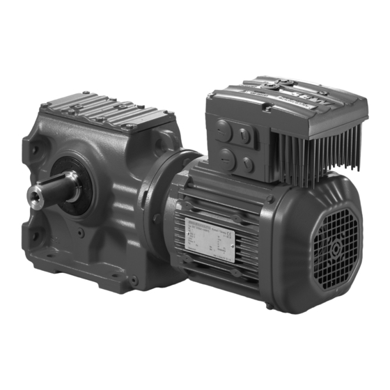
Unit design MOVIMOT drive Unit design MOVIMOT drive ® MOVIMOT drive ® The following figure shows an example of a MOVIMOT drive with helical gear unit: 3992077451 ® [1] MOVIMOT inverter [2] Connection box [3] Motor [4] Helical gear unit ®... -
Page 17: Movimot ® Inverter
Unit design MOVIMOT inverter MOVIMOT inverter ® MOVIMOT inverter ® The following figure shows the connection box and the MOVIMOT inverter: 0 1 2 0 1 2 [10] [11] [5] [12] [13] [14] [15] [16] [17] [18] 9007199880561035 Connection box X10: Plug connector for BEM option ®... - Page 18 Unit design MOVIMOT inverter ® The following figure shows the top side of the MOVIMOT inverter: 1 min 28722977291 [1] X50: Diagnostic interface with screw plug [2] Setpoint potentiometer f1 with screw plug [3] Status LED [4] Identification tag ® 4.2.1 MOVIMOT device properties...
-
Page 19: Fieldbus Interfaces
Unit design Fieldbus interfaces Fieldbus interfaces 4.3.1 MF.21 fieldbus interface 1132777611 [1] Status LEDs [2] Diagnostic interface (underneath the screw fitting) INFORMATION Do not loosen the screw fitting of the diagnostic interface [2] in potentially explosive atmospheres. 4.3.2 Interface bottom side 1132786955 [1] Connection to connection module [2] DIP switches (dependent on variant) - Page 20 Unit design Fieldbus interfaces 4.3.3 Device structure of MFZ connection module The following figure shows the MFZ connection module. 9007200390917003 [1] Terminal strip X20 [2] Isolated terminal block for 24 V through-wiring (NOTICE: Do not use for shielding.) [3] M20 cable gland [4] M12 cable gland [5] Grounding terminal The scope of delivery includes 2 EMC cable glands.
-
Page 21: Movimot Drive Type Designation
Unit design MOVIMOT® drive type designation MOVIMOT® drive type designation ® MOVIMOT drive type designation 4.4.1 Nameplate ® The following figure shows an example of a MOVIMOT drive nameplate. The name- plate is located on the motor. 6205-2Z-J-C3 6205-2Z-J-C3 RF47/II2GD EDRN90L4 BE2/MM15/3D/MO 01.1207730201.0001.11 2020 Jahr... -
Page 22: Movimot® Inverter Type Designation
Unit design MOVIMOT® inverter type designation MOVIMOT® inverter type designation ® MOVIMOT inverter type designation 4.5.1 Nameplate ® The following figure shows an example of a MOVIMOT inverter nameplate: Status: 15 10 10 49/17 836 MM05D-503-14/3D Type: 28262719 1366928 Eingang / Input Ausgang / Output 3x400...500V AC 3x0V...Uin... - Page 23 Unit design MOVIMOT® inverter type designation 4.5.3 Identification tag ® The identification tag [1] on the top of the MOVIMOT inverter provides information about the inverter type [2], inverter part number [3], device power [4]. 1 min 9007203056379787 ® Operating Instructions – Explosion-Protected MOVIMOT MM..D Drives...
-
Page 24: Type Designation Of Fieldbus Interfaces
Unit design Type designation of fieldbus interfaces Type designation of fieldbus interfaces 4.6.1 Nameplate The following figure shows an example of the nameplate of a fieldbus interface: II3D Ex tc IIIC T120°C Dc Feldbus-Schnittstelle / Fieldbus interface Made in Germany TYP: MFP21D/Z21D/3D Sach-NR.:... -
Page 25: Type Designation Of Module Terminal Box
Unit design Type designation of module terminal box Type designation of module terminal box 4.7.1 Nameplate The following figure shows an example of the nameplate of the module terminal box: p# : 08236739 s# : 0921893 .70 -- 14/14 MFZ21D/II3D 28814284043 4.7.2 Type designation... - Page 26 Unit design Identification of explosion-protected drives 4.8.2 Marking in accordance with directives and standards The protection types are linked to equipment groups, categories, potentially explosive atmospheres, minimum degrees of protection and temperature classes, and are indic- ated on the nameplate according to EU Directive 2014/34/EU. The identification according to the standard includes the following symbols: •...
- Page 27 Unit design Identification of explosion-protected drives 4.8.3 Identification for potentially explosive dust atmospheres Example Ex tc Symbol for explosion protection with protection type/protection level IIIC Classification of the dust group T120°C Maximum surface temperature in °C Equipment protection level Classification of the dust group In addition, equipment group III has been split up into three subgroups A, B and C de- pending on the type of dust.
-
Page 28: Mechanical Installation
Mechanical installation Installation notes Mechanical installation Installation notes INFORMATION Observe the general safety notes. WARNING ® Improper installation/disassembly of MOVIMOT drives and mount-on components. Risk of injury. • Adhere to the notes about installation and disassembly. • Before releasing shaft connections, make sure that there are no active torsional moments present (tensions within the system). -
Page 29: Installation Of Movimot Gearmotor
Mechanical installation Installation of MOVIMOT® gearmotor • The ambient temperature corresponds to the specifications in chapter "Technical data" of the operating instructions. Note that the temperature range of the gear unit may also be restricted (see gear unit operating instructions). ®... - Page 30 Mechanical installation Installation of MOVIMOT® gearmotor ® 5.4.2 Installing MOVIMOT NOTICE ® Loss of guaranteed degree of protection if the MOVIMOT inverter is installed incor- rectly or not at all. ® Damage to the MOVIMOT inverter. ® • When removing the MOVIMOT inverter from the connection box, it must be pro- tected from dust and moisture.
-
Page 31: Setpoint Converter Mla12A Installation
• The MLA12A setpoint converter in category 3D is only available in combination ® with a MOVIMOT drive. • Only trained personnel from SEW-EURODRIVE may perform installation and as- ® sembly work on the MOVIMOT connection box. Tightening torques ®... - Page 32 Mechanical installation Tightening torques 5.6.3 Cable glands Observe the manufacturer's specifications and the follow- ing information for cable glands. • Pay attention to the O-ring on the thread [1]. • The thread must be 5 – 8 mm long [2]. 5 – 8 mm [2] 5.6.4 Screw plugs for cable entries Tighten screw plugs with 2.5 Nm.
- Page 33 Mechanical installation Tightening torques 5.6.6 Tightening torques for terminals Use the following tightening torques for terminals during installation: 9007199713346059 0.8 – 1.5 Nm 1.2 – 1.6 Nm 2.0 – 2.4 Nm ® Operating Instructions – Explosion-Protected MOVIMOT MM..D Drives...
-
Page 34: Electrical Installation
Electrical installation Installation notes Electrical installation Installation notes Observe the following information on electrical installation: • Observe the general safety notes. • Comply with all instructions referring to the technical data and the permissible con- ditions where the unit is operated. •... - Page 35 Electrical installation Installation instructions 6.2.2 Connecting power supply cables ® • Nominal voltage and frequency of the MOVIMOT inverter must match the data of the supply system. • Install safety features F11/F12/F13 for line fuses at the beginning of the power ®...
- Page 36 Electrical installation Installation instructions ® 6.2.3 Permitted cable cross section of the MOVIMOT terminals Power terminals Observe the permitted cable cross sections for installation: Power terminals Cable cross section 1.0 mm – 4.0 mm (2 x 4.0 mm Conductor end sleeves • For single assignment: Connect only single-wire conductors or flexible conductors with conductor end sleeves (DIN 46228, material E‑CU) with or without...
- Page 37 Electrical installation Installation instructions 6.2.4 Using the control terminals X5 – X6 Note the following information for actuating the control terminal clamps: Connect conductor Connect conductor without pressing the activation after pressing the activation button. button. 9007199919965835 9007200623153931 The following conductors can be installed When connecting the following conduct- directly (without tools) up to two cross ors, you must press the actuation button...
- Page 38 Electrical installation Installation instructions 6.2.5 Residual current device WARNING No protection against electric shock if an incorrect type of residual current device is used. Severe or fatal injuries. • The product can cause direct current in the PE conductor. If a residual current device (RCD) or a residual current monitoring device (RCM) is used for protec- tion in the event of a direct or indirect contact, only a type B RCD or RCM is per- mitted on the supply end of the product.
- Page 39 Electrical installation Installation instructions 6.2.7 Equipotential bonding According to EN 60079‑14, connection to an equipotential bonding system is required. A second connection option is available on the status housing for this purpose. Ob- serve chapter "Improving the grounding (EMC), HF grounding" (→ 2 40). 6.2.8 Notes on PE connection WARNING...
- Page 40 Electrical installation Installation instructions 6.2.9 EMC-compliant installation INFORMATION This drive system is not designed for operation on a public low voltage grid that sup- plies residential areas. This is a product with restricted availability (categories C1 to C4 according to EN ...
- Page 41 Electrical installation Installation instructions EDRS71, EDRE80, EDRN71 – 80 motors with HF (+NF) grounding 8026768011 Use of the pre-cast bore at the Ground strap (not included in the deliv- stator housing ery) Serrated lock washer Self-tapping screw DIN 7500 M6 × 16, tightening torque 10 Nm Disk ISO 7093 EDRE90, EDRN90 motors with HF (+LF) grounding 8026773131...
- Page 42 Electrical installation Installation instructions EDRE100M, EDRN100LS motors with HF (+LF) grounding 18014402064551947 Use of the pre-cast bore at the Ground strap (not included in the deliv- stator housing ery) Serrated lock washer Self-tapping screw DIN 7500 M6 × 16, tightening torque 10 Nm Disk ISO 7093 EDRE100L –...
- Page 43 ® MOVIMOT drives must not be exposed to harmful radiation (e.g. ionizing radiation). Consult SEW-EURODRIVE, if required. Hazardous gases, vapors and dusts If used according to their designated use, explosion-protected motors are incapable of igniting explosive gases, vapors or dusts. However, explosion-protected motors may...
-
Page 44: Protection Concept
If the motor is operated in environments with high environmental impact, such as in- creased ozone levels, EDR. motors can optionally be equipped with higher-quality gaskets. If you have doubts regarding the stability of the gaskets in connection with the respective environmental impacts, consult SEW-EURODRIVE. Protection concept INFORMATION To avoid exceeding the permissible temperature, you may only operate the ®... - Page 45 Electrical installation Connection – MOVIMOT in conjunction with fieldbus interface • Data lines and 24 V supply Route data lines and 24 V supply separately from cables that emit interference (such as control cables of solenoid valves, motor cables). • Cable glands Select a cable gland with a shield connected over a large area.
- Page 46 Electrical installation Connection – MOVIMOT in conjunction with fieldbus interface • Make sure that any cable entries you are not using are sealed with screw plugs for potentially explosive areas in accordance with EN 60079-0. • The enclosure must be ensured in accordance with the data on nameplate (at least IP54).
- Page 47 Electrical installation Connection – MOVIMOT in conjunction with fieldbus interface Impermissible assembly Recommendation: Assembly with solid connecting wire Assembly with forked cable lug Permitted for cross section Permitted for all cross sections up to max. 2.5 mm 2.5 mm² [1] Forked cable lug suitable for M5 PE screws. Earth-leakage currents ≥ 3.5 mA can occur during normal operation.
- Page 48 Electrical installation Connection – MOVIMOT in conjunction with fieldbus interface [1] Assignment of terminals 19-36 see chapter "Connection of fieldbus interface inputs/outputs (I/O)" (→ 2 51) [2] Ensure equipotential bonding between all bus stations Terminal assignment Name Direction Function X20 1 Input PROFIBUS-DP data line A (incoming) Input PROFIBUS-DP data line B (incoming) DGND...
- Page 49 Electrical installation Connection – MOVIMOT in conjunction with fieldbus interface ® 6.4.4 Connection of MOVIMOT , fieldbus interface close to the motor ® The following wiring diagram shows the connection of MOVIMOT with fieldbus inter- face close to the motor: F11/F12/F13 ®...
- Page 50 Electrical installation Connection – MOVIMOT in conjunction with fieldbus interface ® 6.4.5 Connection of MOVIMOT , fieldbus interface on the drive ® The following wiring diagram shows the connection of MOVIMOT with integrated fieldbus interface: F11/F12/F13 ® MOVIMOT MFZ.. / 3D [2] [3] [4] DC 24 V 3815393419...
- Page 51 Electrical installation Connection – MOVIMOT in conjunction with fieldbus interface 6.4.6 Connection – inputs/outputs (I/O) of fieldbus interfaces The following wiring diagram shows the connection of the digital inputs/outputs of the fieldbus interface: 19 20 21 22 23 24 25 26 27 28 29 30 31 32 33 34 35 36 3815762699 = Potential level 1 = Potential level 2...
-
Page 52: Connection Of Movimot Options
Electrical installation Connection of MOVIMOT® options • Check the polarity of the DC 24 V cable. • Check the polarity of the communication cable. • Provide for the equipotential bonding between the fieldbus interfaces. After the wiring check • Install all the fieldbus interfaces. Connection of MOVIMOT®... - Page 53 Electrical installation Connection of MOVIMOT® options [5] HT1/HT2: Intermediate terminals for temperature switch TH (max. 24 V + 10% to ground) [6] Ready signal (contact closed = ready for operation) [7] Higher-level controller (PLC) [8] Independent evaluation unit with restart lock The independent evaluation unit must contain basic insulation from safe electrically isolated circuits.
- Page 54 Electrical installation Connection of MOVIMOT® options RS485 bus master Independent evaluation unit with restart lock The independent evaluation unit must contain basic insulation from safe electrically isolated circuits. Both directions of rotation are enabled [10] Metal cable gland [11] Equipotential bonding with RS485 bus master ®...
-
Page 55: Connection Of The Rs485 Bus Master
Electrical installation Connection of the RS485 bus master Setpoint changeover f1/f2 HT1/HT2: Intermediate terminals for temperature switch TH (max. 24 V + 10% to ground) Ready signal (contact closed = ready for operation) Setpoint converter MLA12A Connection example with several MLA12A setpoint converters Higher-level controller (PLC) [10] Relay monitoring with restart lock Connection of the RS485 bus master... -
Page 56: Startup
Startup General information concerning startup Startup General information concerning startup INFORMATION You must comply with the general safety notes in chapter "Safety notes" during start- WARNING Risk of crushing due to missing or defective protective covers. Severe or fatal injuries. •... -
Page 57: Requirements
Startup Requirements Requirements The following conditions apply to the startup: ® • The MOVIMOT drive must be installed correctly both mechanically and electrical- • Appropriate safety measures prevent the drives from starting up unintentionally. • Appropriate safety measures must be taken to prevent risk of injury or damage to the machine. - Page 58 Startup Description of the controls 7.3.2 Switch f2 The switch f2 has different functions depending on the operating mode: • Binary control: Setting setpoint f2 (f2 is selected via terminal f1/f2 X6:7,8 = "1") • Control via RS485: Minimum frequency setting f Switch f2 Detent setting Setpoint f2 Hz...
-
Page 59: Description Of The Dip Switches S1
Startup Description of the DIP switches S1 DIP switch S1: Meaning Binary coding Motor pro- Motor PWM fre- No-load RS485 device tection power sec- quency damping address tion No function Variable No function (16, 8, 4 kHz) 4 kHz 1) The motor power stage is always adapted. 2) No-load damping is always disabled. -
Page 60: Description Of Dip Switches S2
Startup Description of DIP switches S2 7.4.2 DIP switch S1/5 Motor protection switched on or switched off SEW-EURODRIVE recommends to always keep the motor protection enabled, i.e. S1/5 = "OFF". Description of DIP switches S2 7.5.1 DIP switches S2/5 – S2/8 Additional functions •... - Page 61 Startup Selectable additional functions MM..D-503-14 7.6.2 Additional function 1 ® MOVIMOT with increased ramp times 329690891 Functional description • It is possible to set ramp times of up to 40 s. • In RS485 control mode, a ramp time of max. 40 s can be transmitted when using 3 process data units.
-
Page 62: Selectable Additional Functions Mm
Startup Selectable additional functions MM..D-503-14 7.6.4 Additional function 10 ® MOVIMOT with reduced torque at low frequencies 330179211 Functional description • When activated, drive monitoring is deactivated by the current limit characteristic. Operating characteristic curves can be permanently exceeded. The TH tempera- ture switch protects against impermissible heating. - Page 63 Startup Selectable additional functions MM..D-503-14 Minimum frequency = 0 Hz Control via RS485: In detent position 0 of switch f2, the minimum frequency with the activated additional function is 0 Hz. All other values that can be set remain unchanged. Switch f2 Detent setting Minimum frequency [Hz] with active additional...
-
Page 64: Startup With Binary Control
Startup Startup with binary control Startup with binary control ® 1. Remove the MOVIMOT inverter from the connection box. ® 2. Check whether the MOVIMOT drive is installed correctly both mechanically and electrically. See chapters "Mechanical installation" and "Electrical installation". 3. - Page 65 Startup Startup with binary control INFORMATION During operation, the first speed is infinitely variable using the setpoint potentiometer f1 which is accessible from outside. Speeds f1 and f2 can be set independently of each other. 7. Set the ramp time at the switch t1. The ramp time is based on a setpoint step change of 1500 min (50 Hz).
- Page 66 Startup Startup with binary control Inverter Terminal signal level Status behavior Supply f1/f2 CW/stop CCW/ system stop X1:L1 – X6:1,2,3 X6:7,8 X6:11,12 X6:9,10 L3 CW rotation Green with f2 CCW rotation Green with f2 Stop Yellow Key: 0 = No voltage 1 = Voltage X = Any 7.7.2...
-
Page 67: Startup With Mla12A Setpoint Converter
Startup Startup with MLA12A setpoint converter Startup with MLA12A setpoint converter WARNING Electric shock from capacitors that have not been fully discharged. Severe or fatal injuries. • Disconnect the inverter from the power. Observe the minimum switch-off time after disconnection from the supply system: –... - Page 68 Startup Startup with MLA12A setpoint converter 7. Make sure the screw plug of the setpoint potentiometer f1 has a seal and screw it NOTICE! Loss of warranted degree of protection if the screw plugs of the f1 set- point potentiometer or the X50 diagnostic interface are installed incorrectly or not at all.
- Page 69 Startup Startup with MLA12A setpoint converter INFORMATION • The TH automatically switches itself back on when the temperature drops below the maximum value. The evaluation unit must prevent the drive from restarting au- tomatically (restart lock). • Do not switch the drive back on until the cause of the problem has been checked. This check must be performed by a trained specialist.
-
Page 70: Easy" Startup With Rs485 Interface/Fieldbus
"Easy" startup with RS485 interface/fieldbus General information concerning startup "Easy" startup with RS485 interface/fieldbus General information concerning startup INFORMATION You must comply with the general safety notes in chapter "Safety notes" during start- WARNING Risk of crushing due to missing or defective protective covers. Severe or fatal injuries. -
Page 71: Requirements
"Easy" startup with RS485 interface/fieldbus Requirements Requirements The following conditions apply to the startup: ® • The MOVIMOT drive must be installed correctly both mechanically and electrical- • Appropriate safety measures prevent the drives from starting up unintentionally. • Appropriate safety measures must be taken to prevent risk of injury or damage to the machine. - Page 72 "Easy" startup with RS485 interface/fieldbus Startup procedure 5. If the ramp time is not specified via the fieldbus, set the ramp time at switch t1. The ramp time is based on a setpoint step change of 1500 min (50 Hz). Switch t1 Detent setting Ramp time t1 s 0.1 0.2 0.3 0.5 0.7...
-
Page 73: Coding Of Process Data
"Easy" startup with RS485 interface/fieldbus Coding of process data [1] Potentiometer setting 9. NOTICE! Loss of warranted degree of protection if the screw plugs of the f1 setpoint poten- tiometer or the X50 diagnostic interface are installed incorrectly or not at all. ®... - Page 74 "Easy" startup with RS485 interface/fieldbus Coding of process data ® MOVIMOT Master 339252747 = Process output data = Process input data = Control word = Status word 1 = Speed [%] = Output current = Ramp = Status word 2 8.4.1 2 process data words ®...
- Page 75 "Easy" startup with RS485 interface/fieldbus Coding of process data 8.4.3 Process output data ® Process output data is sent from the higher-level controller to the MOVIMOT inverter (control information and setpoints). However, they only become effective in the ® ® MOVIMOT inverter if the RS485 address in MOVIMOT (DIP switches S1/1 to S1/4)
- Page 76 "Easy" startup with RS485 interface/fieldbus Coding of process data Control word, bit 9 = apply brake when control command "Stop" is issued ® If bit 9 is set after activating the control command "Stop", the MOVIMOT inverter ap- plies the brake and inhibits the output stage. Speed [%] The speed setpoint is given as a percentage and refers to the maximum speed which you set on the setpoint potentiometer f1.
- Page 77 "Easy" startup with RS485 interface/fieldbus Coding of process data 8.4.4 Process input data ® The MOVIMOT inverter sends back process input data to the higher-level controller. The process input data consists of status information and actual value information. ® The MOVIMOT inverter supports the following process input data: •...
- Page 78 "Easy" startup with RS485 interface/fieldbus Coding of process data PI3: Status word 2 (only for 3-word protocol) 15 14 13 12 11 10 9 8 7 6 5 4 3 2 1 0 Output stage enabled = "1" Inverter ready = "1" PO data enabled = "1"...
- Page 79 "Easy" startup with RS485 interface/fieldbus Coding of process data Assignment status word 1 Meaning Explanation ® Output stage 1: MOVIMOT drive is enabled. enabled ® 0: MOVIMOT drive is not enabled. ® Inverter 1: MOVIMOT drive is ready for operation. ready ®...
- Page 80 "Easy" startup with RS485 interface/fieldbus Coding of process data Assignment of status word 2 Meaning Explanation ® Output stage 1: MOVIMOT drive is enabled. enabled ® 0: MOVIMOT drive is not enabled. ® Inverter 1: MOVIMOT drive is ready for operation. ready ®...
-
Page 81: Function With Rs485 Master
"Easy" startup with RS485 interface/fieldbus Function with RS485 master Function with RS485 master ® • The higher-level controller (e.g. PLC) is the master, the MOVIMOT inverter is the slave. • 1 start bit, 1 stop bit and 1 parity bit (even parity) will be used. ®... - Page 82 "Easy" startup with RS485 interface/fieldbus Function with RS485 master 8.5.2 Idle and start delimiter ® The MOVIMOT inverter detects the start of a request message by means of an idle period lasting at least 3.44 ms, followed by the character 02 (start delimiter 1).
- Page 83 "Easy" startup with RS485 interface/fieldbus Function with RS485 master Example The following figure gives an example of how a block check character is created for an acyclical message of type PDU 85 with 3 process data items. The XOR logic opera- tion on the characters SD1 –...
- Page 84 "Easy" startup with RS485 interface/fieldbus Function with RS485 master ® 8.5.8 Message processing in the MOVILINK master ® The following algorithm must be used for sending and receiving MOVILINK mes- sages in any programmable controllers, in order to ensure correct data transmission. a) Send request message ®...
- Page 85 "Easy" startup with RS485 interface/fieldbus Function with RS485 master 8.5.9 Sample message ® This example deals with the control of a MOVIMOT drive using three process data words of PDU type 85 (3 PD acyclical). The RS485 master sends three process out- ®...
-
Page 86: Startup With Mfp Profibus Interface
"Easy" startup with RS485 interface/fieldbus Startup with MFP PROFIBUS interface Startup with MFP PROFIBUS interface INFORMATION Switch off the DC 24 V supply before removing/mounting the fieldbus interface. ® 1. Remove the MOVIMOT inverter from the connection box. ® 2. Check whether the MOVIMOT drive is installed mechanically and electrically in accordance with the regulations. - Page 87 "Easy" startup with RS485 interface/fieldbus Startup with MFP PROFIBUS interface WARNING Electric shock from capacitors that have not been fully discharged. Severe or fatal injuries. • Disconnect the inverter from the power. Observe the minimum switch-off time after disconnection from the supply system: –...
- Page 88 Refer to the relevant configuration software manuals for details on the procedure. INFORMATION The latest version of the GSD files is always available on the Internet at the following address: http://www.SEW-EURODRIVE.de Project planning for the PROFIBUS DP interface MFP 1. Observe the notes in the README.TXT file on the GSD disk.
-
Page 89: Function Of Mfp Profibus Interface
"Easy" startup with RS485 interface/fieldbus Function of MFP PROFIBUS interface Function of MFP PROFIBUS interface 8.7.1 Meaning of the LED indicators The PROFIBUS interface MFP has 3 diagnostic LEDs. • "RUN" LED (green) for displaying the normal operating state. • "BUS-F"... - Page 90 "Easy" startup with RS485 interface/fieldbus Function of MFP PROFIBUS interface "RUN" LED (green) RUN BUS-F SYS-F Meaning Troubleshooting • MFP components hardware – • Correct MFP operation – • MFP is currently exchan- ging data with the DP mas- ter (data exchange) and ®...
- Page 91 "Easy" startup with RS485 interface/fieldbus Function of MFP PROFIBUS interface BUS-F SYS-F Meaning Troubleshooting Flashes • MFP operating state • Evaluate the fault number ® of MOVIMOT status 1 × word 1 in the controller. ® • MOVIMOT signals ® a fault •...
-
Page 92: Expert" Startup With Parameter Function
"Expert" startup with parameter function "Expert" startup with parameter function INFORMATION Startup in expert mode is only required if you want to set parameters during startup. Startup in expert mode is only possible if: • No additional function is activated (DIP switch S2/5 - S2/8 is set to "OFF") •... -
Page 93: Operation
Operation Operating notes Operation 10.1 Operating notes WARNING Electric shock caused by dangerous voltages at the connections, cables and motor terminals. When the device is switched on, dangerous voltages are present at the connections as well as at any connected cables and motor terminals. This also applies even when the device is inhibited and the motor is at standstill. -
Page 94: Operating Display
Operation Operating display 10.2 Operating display ® The status LED is located on the top of the MOVIMOT inverter. 1 min 18014398969241739 ® [1] MOVIMOT status LED 10.3 Drive ID module The pluggable Drive ID module is installed in the basic unit. ®... - Page 95 Operation Drive ID module If, during a device replacement • the DIP switch setting is not transmitted correctly, ® • or a MOVIMOT inverter with a different part number is used (e.g. with a different device power,) ® the MOVIMOT inverter detects a change in configuration.
-
Page 96: Service
Service Status and error display Service 11.1 Status and error display 11.1.1 Meaning of the status LED ® The status LED is located on the top of the MOVIMOT inverter. ® The 3-color status LED indicates the operating and error states of the MOVIMOT verter. - Page 97 Service Status and error display Meaning Possible cause Color Operating state State error code Fault 08 Speed monitoring error (only when S2/4 = "ON") Flashing slowly or additional function 13 is active. Fault 09 Startup fault Additional functions 4, 5, 12 (DIP switches S2/5 – S2/8) are not permitted.
- Page 98 Service Status and error display 11.1.2 Error list The following table helps you with troubleshooting: Code Error Possible cause Measure – Communication Missing connection' and Check and establish the connection, espe- timeout RS+, RS- between cially ground. ® MOVIMOT and RS485 (motor stops, without master error code)
- Page 99 Correct the settings of DIP switches S2/5 – 5, 12 are not permitted for S2/8. ® MOVIMOT MM..D with AS-Interface. Firmware does not support Contact SEW-EURODRIVE Service. MLK..A option (only with ® MOVIMOT with AS-Inter- face). Thermal Heat sink is dirty.
- Page 100 Contact SEW EURODRIVE Service if the error re-occurs. External terminal External signal at terminal Correct/reset external fault. X6: 9,10 not present. System software Internal fault Contact SEW-EURODRIVE Service. error Communication Communication timeout Check/re-establish the communication link timeout during cyclical communica- between the RS485 master and the ®...
- Page 101 Thermal overload of brake Extend the ramp time. ture coil Reset the fault Brake coil is defective. Contact SEW-EURODRIVE Service. Brake coil and braking re- Connect either brake or braking resistor to sistor connected. drive. Inverter does not match the Check the combination of motor (brake coil) ®...
-
Page 102: Inspection And Maintenance
MOVIMOT inverter. The fieldbus interface re- ports the error only to the higher-level control- ler. EEPROM checksum Defective EEPROM Contact SEW-EURODRIVE Service. error Copy error DBG keypad or PC/laptop Before acknowledging the error, load the fac- disconnected during the tory setting or the complete data set from the ®... -
Page 103: Unit Replacement
Service Unit replacement ® 11.2.3 Gear unit (only for MOVIMOT gearmotors) The gear unit requires regular inspection and maintenance work. Observe the notes and instructions in chapter "Inspection/Maintenance" of the gear unit operating instructions. 11.3 Unit replacement WARNING Electric shock from capacitors that have not been fully discharged. Severe or fatal injuries. - Page 104 Service Unit replacement ® 4. Unlock the drive ID module of the new MOVIMOT inverter and pull it out carefully. 18014399028685579 ® 5. Unlock the drive ID module of the previous MOVIMOT inverter as well and pull it out carefully. ®...
-
Page 105: Electronics Service By Sew-Eurodrive
Electronics Service by SEW‑EURODRIVE If you are unable to rectify a fault, contact SEW‑EURODRIVE Service. For the ad- dresses, refer to www.sew-eurodrive.com. When contacting SEW‑EURODRIVE Service, always specify the following information so that our service personnel can assist you more effectively: •... - Page 106 Service Waste disposal If you have not performed maintenance regularly, SEW‑EURODRIVE recommends that you increase the line voltage slowly up to the maximum voltage. This can be done, for example, by using a variable transformer for which the output voltage has been set according to the following overview.
-
Page 107: Technical Data
Technical data Motor with operating point 400 V/50 Hz or 400 V/100 Hz Technical data Motor with operating point 400 V/50 Hz or 400 V/100 H 12.1 Motor with operating point 400 V/50 Hz or 400 V/100 Hz ® MOVIMOT type 03D- 05D- 07D- 11D- 15D-50 22D-50 30D-50 40D-50 503-14 503-14 503-14 503-14 3-14 3-14... - Page 108 Technical data Motor with operating point 400 V/50 Hz or 400 V/100 Hz ® MOVIMOT type 03D- 05D- 07D- 11D- 15D-50 22D-50 30D-50 40D-50 503-14 503-14 503-14 503-14 3-14 3-14 3-14 3-14 Part number 282627 282627 282627 282627 282627 282627 282627 282627 Size 1 Size 2 Size 2L Degree of protection...
- Page 109 Technical data Motor with operating point 400 V/50 Hz or 400 V/100 Hz ® MOVIMOT type 03D- 05D- 07D- 11D- 15D-50 22D-50 30D-50 40D-50 503-14 503-14 503-14 503-14 3-14 3-14 3-14 3-14 Part number 282627 282627 282627 282627 282627 282627 282627 282627 Size 1 Size 2 Size 2L Output relay...
-
Page 110: Technical Data Of Option Mla12A 3D
Technical data Technical data of option MLA12A 3D 12.2 Technical data of option MLA12A 3D MLA12A 3D Part number 0 823 234 2 Function Setpoint converter Input voltage X9 / X10 AC 400 – 500 V ± 10% Output voltage DC 24 V ± 25 % (max. 200 mA) 0 V reference potential Terminals Tl. -
Page 111: Diagnostic Interface
Technical data Diagnostic interface 12.4 Diagnostic interface Diagnostic interface X50 Standard RS485 to EIA standard (with integrated dynamic terminating resistor) Baud rate 9.6 kbaud Start bits 1 start bit Stop bits 1 stop bit Data bits 8 data bits Parity 1 parity bit, completing for even parity (even parity) Data direction... - Page 112 Technical data Permitted operating modes 12.6.1 4Q operation with motors with a mechanical brake • In 4Q operation, the brake coil can be used as a braking resistor. • You must not connect an external braking resistor. • Brake voltage is generated internally within the unit, which means it independent of the grid.
- Page 113 The brake resistor is integrated in the connection box of MOVIMOT as standard in motors without mechanical brake. • For applications with low regenerative energy, SEW-EURODRIVE recommends 4Q operation. • The resistor protects itself (reversible) against regenerative overload by changing abruptly to high resistance and no longer consuming any more energy. The in- verter then switches off and issues an "overvoltage"...
-
Page 114: Overhung And Axial Loads For Motor Shaft Ends
Technical data Overhung and axial loads for motor shaft ends 12.7 Overhung and axial loads for motor shaft ends 12.7.1 Permitted overhung load You can read the maximum permitted overhung load F of the respective motor de- pending on the point of force application relative to the shaft shoulder from the follow- ing diagrams. - Page 115 Technical data Overhung and axial loads for motor shaft ends The following diagram shows an example of how you can read the maximum over- hung load from the diagram: 1400 1200 Ø14x30 1000 Ø19x40 x/mm 18014402489974539 Motor with shaft diameter 14 mm, force application x at 22 mm, maximum permit- ted overhung load F = 600 N Motor with shaft diameter 19 mm, force application x at 30 mm, maximum permit-...
- Page 116 Technical data Overhung and axial loads for motor shaft ends The information considers the rated speed n and the higher-level rated torque M continuous duty (S1) of the motor. For duty types other than S1 (e.g. S2, S3, etc.), the permitted values for F and F have to be multiplied with the factor 0.8.
- Page 117 Technical data Overhung and axial loads for motor shaft ends Overhung load diagram EDRN80 1400 Ø19X40 1200 1000 x [mm] 28379276939 Overhung load diagram EDRN90 2500 Ø24X50 2000 1500 1000 x [mm] 28379349771 ® Operating Instructions – Explosion-Protected MOVIMOT MM..D Drives...
-
Page 118: Permitted Rolling Bearing Types
Technical data Permitted rolling bearing types Overhung load diagram EDRN100 3000 Ø28X60 2500 2000 1500 1000 x / mm 28379396491 12.8 Permitted rolling bearing types Motor type A-side bearing B-side bearing IEC motor Gearmotor AC motor Brakemotor EDRN71 6204-2Z-J-C3 6303-2Z-J-C3 6203-2Z-J-C3 6203-2RS-J-C3 EDRN80... -
Page 119: Lubricant Tables
Technical data Lubricant tables 12.9 Lubricant tables 12.9.1 Lubricant table for rolling bearings INFORMATION Use of wrong bearing grease can damage the bearings. Motors with sealed bearings The bearings are 2Z or 2RS closed bearings and cannot be re-lubricated. They are used for EDR..71 –... -
Page 120: 12.11 Operating Characteristics
Technical data Operating characteristics 12.11 Operating characteristics ® • The operating characteristics indicate the torques with which the MOVIMOT units may be loaded depending on the speed. • Permanent overload results in excessive heating. • Short-term overloads are permitted. W 3 × 400 – 500 V (400 V) 12.11.1 1400 min 1000 1500... -
Page 121: 12.12 Braking Torque Assignment
Technical data Braking torque assignment 12.12 Braking torque assignment Motor type Brake type Braking torque steps EDRN71S BE05 EDRN71M EDRN80MK EDRN80M EDRN90 EDRN100 12.13 Braking work, working air gap, and brake lining carrier thickness If the brake is used in combination with a safety encoder, or if the brake is designed as safety brake, the maximum values for the working air gap and for the braking work un- til maintenance are reduced. -
Page 122: 12.15 Assignment Of Internal Braking Resistors
Technical data Assignment of internal braking resistors 12.15 Assignment of internal braking resistors The delivery includes 2 screws of size M4 × 8 each. ® MOVIMOT type Braking resistor MM03D-503-14 – MM15D-503-14 BW1, part number 08228973 MM22D-503-14 – MM40D-503-14 BW2, part number 08231362 12.16 PROFIBUS interface MFP21D/Z21D/3D Electrical specification MFP Power supply to MFP control... - Page 123 Technical data PROFIBUS interface MFP21D/Z21D/3D PROFIBUS specifications Supported baud rates 9.6 kBaud – 1.5 MBaud / 3 – 12 MBaud (with automatic detection) Bus termination Integrated, can be set via DIP switch to EN 50170 (V2) Permitted cable length for • 9.6 kBaud: 1200 m To extend the length, several seg- PROFIBUS ments can be coupled using repeat- •...
-
Page 124: Declaration Of Conformity
Declaration of conformity Declaration of conformity EU Declaration of Conformity Translation of the original text 901170411/EN SEW-EURODRIVE GmbH & Co. KG Ernst-Blickle-Straße 42, D-76646 Bruchsal declares under sole responsibility that the following products ® Frequency inverters of the series MOVIMOT MM..D-..3-04... - Page 125 Declaration of conformity EU Declaration of Conformity Translation of the original text 900520610/EN SEW-EURODRIVE GmbH & Co. KG Ernst-Blickle-Straße 42, D-76646 Bruchsal declares under sole responsibility that the following products Fieldbus interface of the series MFI21./.../3D MFP21./.../3D MLA12./3D Category Designation II 3D Ex tc IIIC T120°C Dc...
-
Page 126: Index
Index Index Numerical Configuration PROFIBUS master ......... 88 24 V supply............ 43 Connection 4Q operation.......... 112, 113 Digital inputs/outputs ........ 51 Inputs/outputs.......... 51 Fieldbus interface ........... 44 Additional function 1 .......... 61 Fieldbus interface of the drive ...... 50 Additional function 10 .......... 62 Fieldbus interface, close to the motor .... - Page 127 Index Documents, additional ......... 10 Idle............... 82 Drive ID module........... 94 Improving the grounding........ 40 Description ............. 94 In the open, installation in........ 30 Disassembly .......... 104 Inputs/outputs, connection ........ 51 Technical Data .......... 111 Inspection ............ 102 Dusts .............. 43 installation Electrical............
- Page 128 Index ® MOVIMOT replacement ........ 103 Radiation, hazardous .......... 43 Ramp times ............ 58 Nameplate Ramp times, increased........ 61 Fieldbus interface ........... 24 Repair .............. 105 Inverter ............ 22 Replacing units .......... 103 ® MOVIMOT drive.......... 21 Request message .......... 85 Notes Requirements for startup .......
- Page 129 Index Shut down ............ 105 Terminals Signal words in safety notes........ 8 Connection cross section ....... 46 Start delimiter ............ 82 Current carrying capacity ....... 46 Startup Terminals, actuating .......... 37 Easy with fieldbus interface...... 70 Tightening torques.......... 31 Expert mode ........... 92 Timeout monitoring..........
- Page 132 SEW-EURODRIVE—Driving the world SEW-EURODRIVE GmbH & Co KG Ernst-Blickle-Str. 42 76646 BRUCHSAL GERMANY Tel. +49 7251 75-0 Fax +49 7251 75-1970 sew@sew-eurodrive.com www.sew-eurodrive.com...
Need help?
Do you have a question about the MOVIMOT MM D Series and is the answer not in the manual?
Questions and answers