
Related Manuals for SEW-Eurodrive MOVIGEAR DAC B


Summary of Contents for SEW-Eurodrive MOVIGEAR DAC B
- Page 1 Drive Technology \ Drive Automation \ System Integration \ Services Operating Instructions Mechatronic Drive System ® MOVIGEAR DAC B Direct AS-Interface Communication Edition 04/2010 16888812 / EN...
- Page 2 SEW-EURODRIVE—Driving the world...
-
Page 3: Table Of Contents
Important Information ..................6 How to use the operating instructions ............6 Structure of the safety notes ............... 6 Rights to claim under limited warranty ............7 Exclusion of liability..................7 Copyright notice ..................7 Safety Notes ......................8 General ....................... 8 Target group .................... - Page 4 Electrical Installation ..................51 Installation planning considering EMC aspects ........51 Installation instructions................52 Terminal assignment ................60 ® Connection of MOVIGEAR ..............62 Cable routing and cable shielding ............. 63 Plug connectors ..................66 Plug connector assignment ..............69 Optional plug connector assignment............
- Page 5 11.4 Resetting error messages ............... 187 11.5 Description of status and operating indicators ........188 11.6 AS-Interface bus monitor ................ 193 11.7 Unit replacement ..................194 11.8 SEW-EURODRIVE Service ..............195 11.9 Extended storage..................196 11.10 Disposal ....................197 Inspection and Maintenance ................198 12.1 Determining the operating hours.............
-
Page 6: Important Information
If you are unclear about any of the information in this documentation, or if you require further information, contact SEW-EURODRIVE. Structure of the safety notes The safety notes in these operating instructions are designed as follows:... -
Page 7: Rights To Claim Under Limited Warranty
MOVIGEAR and to achieve the specified product and performance features. SEW-EURODRIVE does not assume liability for injury to persons or damage to equipment or property resulting from non-observance of these operating instructions. In such cases, any liability for defects is excluded. -
Page 8: Safety Notes
If you are unclear about any of the information in this documentation, please contact SEW-EURODRIVE. General Never install or start up damaged products. Submit a complaint to the shipping company immediately in the event of damage. -
Page 9: Designated Use
Safety Notes Designated use Designated use ® MOVIGEAR drive units are components intended for installation in electrical systems or machines. ® In case of installation in machines, startup of the MOVIGEAR drive units (i.e. start of designated operation) is prohibited until it is determined that the machine meets the requirements stipulated in the EC Directive 2006/42/EC (machine directive). -
Page 10: Installation
Safety Notes Installation Installation The units must be installed and cooled according to the regulations and specifications in the corresponding documentation. ® Protect the MOVIGEAR drive units from improper strain. The following applications are prohibited unless the unit is explicitly designed for such use: •... -
Page 11: Operation
Safety Notes Operation Operation ® Systems with integrated MOVIGEAR drive units must be equipped with additional monitoring and protection devices according to the applicable safety guidelines, such as the law governing technical equipment, accident prevention regulations, etc. Additional protective measures may be necessary for applications with increased potential risk. ®... -
Page 12: Unit Design
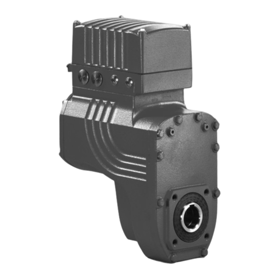
Unit Design ® MOVIGEAR drive unit Unit Design ® MOVIGEAR drive unit ® MOVIGEAR drive units are made up of 3 core components: gear unit, motor and drive electronics. These 3 core components are included in one cast aluminum housing (see following figure). -
Page 13: Shaft Variants
Unit Design Shaft variants Shaft variants ® MOVIGEAR is available with the following shaft variants: ® 3.2.1 MOVIGEAR with hollow shaft and keyway (MGFA..) ® The following figure shows a MOVIGEAR unit with hollow shaft and keyway: 2690820619 ® ® 3.2.2 MOVIGEAR with TorqLOC... -
Page 14: Housing Mounting
Unit Design Housing mounting Housing mounting 3.3.1 Torque arm (MGF.T) The following figure shows the torque arm for MGF.T: 2690826379 3.3.2 Housing with threads (MGF.S) The following figure shows the housing type with threads for mounting a torque arm. This type does not include a centering shoulder, which means it is not suitable for direct installation to the machine: 2690824459 Operating Instructions –... -
Page 15: Position Of The Cable Entry
Unit Design Position of the cable entry Position of the cable entry ® The following cable entries are possible for MOVIGEAR • Position X + 2 – X: 2 x M25 x 1.5 + 1 x M16 x 1.5 + 1 x M16 x 1.5 –... -
Page 16: Sample Nameplate And Type Designation Of Drive Unit
Unit Design Sample nameplate and type designation of drive unit Sample nameplate and type designation of drive unit 3.5.1 Nameplate ® The following figure gives an example of a MOVIGEAR nameplate. For the structure of the type designation, refer to chapter "Type designation". 76646 Bruchsal/Germany MGFAT2-DSM-DAC-B/DSP a pk... -
Page 17: Movigear ® Electronics
Unit Design ® MOVIGEAR electronics ® MOVIGEAR electronics ® 3.6.1 MOVIGEAR electronics cover (inside) and connection box ® The following figure shows the connection box and the bottom side of the MOVIGEAR electronics cover: [10] 1 2 3 4 1 2 3 4 ADE04SA ADE04SA 34567... - Page 18 Unit Design ® MOVIGEAR electronics 3.6.2 AS-Interface option The AS-Interface option is located on the connection board in the connection box. ® MOVIGEAR DAC is available with the following AS-Interface variants: • GLK30A binary slave • GLK31A double slave for drive with several speed setpoints and ramps ®...
- Page 19 Unit Design ® MOVIGEAR electronics GLK31A double The GLK31A option works as a double slave on AS-Interface according to AS-Interface slave specification 3.0. ® The serial AS-Interface data transmission (analog profile) allows for MOVIGEAR parameters and display values to be written and read. ®...
-
Page 20: Sample Nameplate And Type Designation For Electronics
Unit Design Sample nameplate and type designation for electronics Sample nameplate and type designation for electronics 3.7.1 Nameplate of electronics cover ® The following figure gives an example of a MOVIGEAR nameplate. For the structure of the type designation, refer to chapter "Type designation". 2585095947 [1] Nameplate of connection unit [2] Electronics cover nameplate... - Page 21 Unit Design Sample nameplate and type designation for electronics 3.7.3 Type designation of connection unit The following table shows the type designation of the connection unit: M G x B – DAC / DSP Connection unit option DSP = Electrodynamic ®...
-
Page 22: Movigear
Unit Design ® MOVIGEAR with optional package for wet areas ® MOVIGEAR with optional package for wet areas 3.8.1 Properties ® The following figure shows the additional features of MOVIGEAR drive units with the optional package for applications in wet areas: [11] [10] [12]... -
Page 23: Mechanical Installation
Mechanical Installation Installation notes Mechanical Installation Installation notes INFORMATION Comply with the safety notes during installation. CAUTION ® Improper installation/disassembly of MOVIGEAR and mount-on components. Risk of injury. • Note the information about installation and disassembly in this chapter. • Before releasing shaft connections, make sure that there are no active torsional moments present (tensions within the system). -
Page 24: Installation Prerequisites
Mechanical Installation Installation prerequisites Installation prerequisites Check that the following conditions have been met: ® • The entries on the nameplate of the MOVIGEAR unit match the voltage supply system. • The drive is undamaged (no damage caused by transportation or storage) •... - Page 25 Mechanical Installation ® Installing MOVIGEAR 4.4.1 Minimum installation clearance of electronics cover Note the minimum installation clearance (see following figure) required to remove the ® MOVIGEAR electronics cover. For detailed dimension drawings, see chapter "Technical data and dimension sheets". 2350097419 NOTICE ®...
- Page 26 MOVIGEAR drive units ordered for a universal mounting position are delivered by separately SEW-EURODRIVE with a separately included breather valve. included breather In this case, the breather valve is delivered in the hollow shaft of the drive unit. Before valve startup, you must replace the highest oil screw plug with the provided breather valve.
-
Page 27: Shaft-Mounted Gear Unit With Keyway
Mechanical Installation Shaft-mounted gear unit with keyway Shaft-mounted gear unit with keyway INFORMATION Observe the design notes in chapter "Technical data and dimension sheets" for the customer shaft design. 4.5.1 Assembly instructions ® 1. Apply NOCO fluid 2348641291 ® 2. Distribute NOCO fluid carefully 2348643211 Operating Instructions –... - Page 28 [2] Lock washer [3] Washer [4] Retaining ring [6] Customer shaft 3B: Installation with the SEW-EURODRIVE assembly/disassembly kit. Observe chapter "Technical data and dimension sheets/ Design notes for gear units with hollow shaft and key". Customer shaft with contact shoulder...
- Page 29 4. Tighten the retaining bolt to the appropriate torque (see table). 2348211211 Drive Screw Tightening torque [Nm] MGFA.2 MGFA.4 INFORMATION To avoid contact corrosion, SEW-EURODRIVE recommends that the customer shaft should additionally be lathed down between the 2 contact surfaces. Operating Instructions – MOVIGEAR® DAC-B...
- Page 30 [4] Retaining ring [5] Spacer tube [6] Customer shaft 3. Insert the forcing disk [8] and the fixed nut [7] from the SEW-EURODRIVE installa- tion/removal kit between the customer shaft [6] and the retaining ring [4]. 4. Re-install the retaining ring [4].
-
Page 31: Shaft-Mounted Gear Unit With Torqloc (Customer Shaft Without Contact Shoulder)
Mechanical Installation ® Shaft-mounted gear unit with TorqLOC ® Shaft-mounted gear unit with TorqLOC (customer shaft without contact shoulder) 1. Clean the inside of the hollow shaft and the customer shaft carefully. Ensure that all traces of grease or oil are removed. Install the stop ring and the bushing on the customer shaft. - Page 32 Mechanical Installation ® Shaft-mounted gear unit with TorqLOC 4. Push the gear unit onto the customer shaft. 2348983691 5. Preassemble the torque arm (do not tighten the screws). 2348979851 6. Push the busing onto the gear unit up to the stop. 2348972171 Operating Instructions –...
- Page 33 Mechanical Installation ® Shaft-mounted gear unit with TorqLOC 7. Secure the bushing with the split ring. Tighten the split ring on the bushing using the appropriate torque as specified in the following table. 2348974091 Type Tightening torque [Nm] Standard design Stainless steel MGFT.2 MGFT.4...
- Page 34 Mechanical Installation ® Shaft-mounted gear unit with TorqLOC 9. Push the counter bushing onto the customer shaft and into the hollow shaft all the way to the seat. 2348981771 10.Tap lightly on the collar of the counter bushing to ensure that the bushing is fitted securely in the hollow shaft.
- Page 35 Mechanical Installation ® Shaft-mounted gear unit with TorqLOC 12.Tighten the locking bolts by working round several times from one bolt to the next (not in diametrically opposite sequence). See the table for tightening torques. NOTICE After installation, the remaining gap between the outer rings of the shrink disks must be >...
-
Page 36: Shaft-Mounted Gear Unit With Torqloc ® (Customer Shaft With Contact Shoulder)
Mechanical Installation ® Shaft-mounted gear unit with TorqLOC 14.Tighten the torque arm; observe chapter "Torque arm". 2348977931 ® Shaft-mounted gear unit with TorqLOC (customer shaft with contact shoulder) 1. Clean the inside of the hollow shaft and the customer shaft carefully. Ensure that all traces of grease or oil are removed. - Page 37 Mechanical Installation ® Shaft-mounted gear unit with TorqLOC 2. Slide the bushing onto the customer shaft. 0 mm 2349377035 ® 3. Apply NOCO fluid to the bushing and distribute it carefully. 2349367435 4. Push the gear unit onto the customer shaft. 2348992395 Operating Instructions –...
- Page 38 Mechanical Installation ® Shaft-mounted gear unit with TorqLOC 5. Slide the shrink disk onto the hollow shaft. Ensure that all screws have been loosened. 2349371275 6. Push the counter bushing onto the customer shaft and into the hollow shaft all the way to the seat.
- Page 39 Mechanical Installation ® Shaft-mounted gear unit with TorqLOC 8. Manually tighten the screws of the shrink disk and ensure that the end rings of the shrink disk are parallel. 2349369355 9. Tighten the locking screws by working round several times from one screw to the next (not in diametrically opposite sequence).
- Page 40 Mechanical Installation ® Shaft-mounted gear unit with TorqLOC 10.The distance between the counter bushing and the hollow shaft end must match the values in the following figure: > 0 mm > 0 mm 2348661131 11.Preassemble the torque arm (do not tighten the screws). 2352754955 12.Tighten the torque arm;...
-
Page 41: Installing The Protective Cover
Mechanical Installation Installing the protective cover Installing the protective cover NOTICE During operation, output components are in fast motion. Risk of jamming and crushing. • Disconnect the drive from the power supply and safeguard it against accidental startup before starting work and. •... -
Page 42: Torque Arm
Mechanical Installation Torque arm 4.8.2 Installation without cover In certain individual cases (e.g. through-shaft), you cannot install the cover. In these cases, the cover is not necessary if the system or unit manufacturer provides corresponding components to guarantee for the compliance with the required degree of protection. -
Page 43: 4.10 Tightening Torques
Mechanical Installation Tightening torques 4.10 Tightening torques Warning ® The surface temperatures of the MOVIGEAR and the application options can be very high during operation. Danger of burns. ® • Do not touch the MOVIGEAR drive and application options until they have cooled down sufficiently. - Page 44 Mechanical Installation Tightening torques 4.10.2 Cable glands Tightening torques Tighten the EMC cable glands optionally included in the delivery with the following tightening torques: Screw fitting Part number Size Tightening torque EMC cable glands (nickel-plated 1820 478 3 M16 x 1.5 3.5 Nm to 4.5 Nm brass) 1820 480 5...
- Page 45 Mechanical Installation Tightening torques ® 4.10.3 MOVIGEAR electronics cover ® Tighten the screws on the MOVIGEAR electronics cover using 6.0 Nm working diagonally across. 2350592011 Operating Instructions – MOVIGEAR® DAC-B...
-
Page 46: Movigear ® With Optional Package For Wet Areas
MOVIGEAR with optional package for wet areas INFORMATION SEW-EURODRIVE guarantees that the HP200 special surface is free from faults when delivered. Report any transportation damage immediately. Although the housing surfaces have a high impact resistance, they are to be handled with care. - Page 47 – Position X (not possible in conjunction with M6) ® Mounting The following figure shows the position of MOVIGEAR in mounting positions M1 to M6. positions 2351031563 = Mounting position M3 only after consultation with SEW-EURODRIVE Operating Instructions – MOVIGEAR® DAC-B...
- Page 48 Mechanical Installation ® MOVIGEAR with optional package for wet areas 4.11.2 Tightening torques regarding the optional package for applications in wet areas WARNING ® The surface temperature of the MOVIGEAR can be very high during operation. Danger of burns. ® •...
- Page 49 Mechanical Installation ® MOVIGEAR with optional package for wet areas ® ® MOVIGEAR Proceed as follows when installing the MOVIGEAR electronics cover: electronics cover 2351658251 ® Steps 1. Fix the MOVIGEAR cover in position on the connection box with a tightening torque of 2 Nm 2.
- Page 50 Mechanical Installation ® MOVIGEAR with optional package for wet areas EMC cable glands Tighten the EMC cable glands optionally included in the delivery with the following tightening torques: Screw fitting Part number Size Tightening torque EMC cable glands (nickel-plated 1820 478 3 M16 x 1.5 3.5 Nm to 4.5 Nm brass)
-
Page 51: Electrical Installation
Installation must be carried out with great care. • Note the connection examples in chapter "Installation instructions / Cable routing and cable shielding". INFORMATION Additional information is available in the SEW-EURODRIVE publication "Drive Engineering – Practical Implementation, EMC in Drive Engineering". Operating Instructions – MOVIGEAR® DAC-B... -
Page 52: Installation Instructions
Electrical Installation Installation instructions Installation instructions 5.2.1 Connecting the supply system leads ® • The rated voltage and rated frequency of MOVIGEAR must correspond with the supply system data. • Cable cross section: according to input current I at rated power (see chapter supply "Technical data and dimension sheets"). - Page 53 Electrical Installation Installation instructions 5.2.2 Permitted cable cross section of the terminals Supply system Observe the permitted cable cross sections for installation: terminals Supply system terminals Connection cross section 1.0 mm - 4.0 mm Connection cross section AWG17 - AWG12 (AWG) Conductor end sleeves •...
- Page 54 Electrical Installation Installation instructions 5.2.3 Actuating the control terminal clamps Note the following information for actuating the control terminal clamps: Control terminals (the following figure shows a schematic illustration) 2378449419 5.2.4 Actuating the communication terminal clamps Note the following information for actuating the communication terminal clamps: Connecting the conductor Connecting the conductor without pushing the actuation button...
- Page 55 Electrical Installation Installation instructions Removing the conductor, after pressing the actuation button 2378520459 Before removing the conductor, first press the actuation button on top. Operating Instructions – MOVIGEAR® DAC-B...
- Page 56 Install the fuses at the beginning of the supply system leads behind the supply bus junction. • SEW-EURODRIVE recommends that you do not use earth-leakage circuit breakers. However, if an earth-leakage circuit breaker is stipulated for direct or indirect protec- tion against contact, observe the following note in accordance with EN 61800-5-1: WARNING Wrong type of earth-leakage circuit breaker installed.
- Page 57 Electrical Installation Installation instructions ® 5.2.7 Notes on PE connection of MOVIGEAR DANGER Incorrect connection of PE. Death, severe injuries or damage to property from electric shock. • The permitted tightening torque for the screw fitting is 2.0 to 2.4 Nm (18...21 lb.in). •...
- Page 58 EMC interference. In this case, it may be recommended for the operator to carry out suitable measures. • For detailed information on EMC compliant installation, refer to the publication "Electromagnetic Compatibility in Drive Engineering" from SEW-EURODRIVE. 5.2.9 Installation altitudes above 1000 m asl ®...
- Page 59 Electrical Installation Installation instructions 5.2.11 Information regarding UL Field wiring power Observe the following notes for UL-compliant installation: terminals • Use 75 °C copper wire only • Tighten power terminals to 10.6 – 12.4 lb.in (1.2 – 1.4 Nm) Short circuit Suitable for use on a circuit capable of delivering not more than 200,000 rms current rating symmetrical amperes:...
-
Page 60: Terminal Assignment
Electrical Installation Terminal assignment Terminal assignment DANGER The drive is operated as a generator when the hollow shaft is turned. Severe or fatal injuries from electric shock. • Secure the output shaft against rotation when the electronics cover is removed. ®... - Page 61 Electrical Installation Terminal assignment Assignment Terminal Name Color Function (permitted tightening torque) Communi- – – AS-Interface data cable + cation – AS− – AS-Interface data cable – terminals – – DI2 sensor input – – DI3 sensor input – VO24 –...
-
Page 62: Connection Of Movigear
The STO input may only be jumpered with 24 V if MOVIGEAR does not perform any safety function. Local operation Automatic mode active Local mode active F11/F12/F13 MOVIGEAR DAC B ® Connection Functions of the CW/Stop and CCW/Stop AS-Interface terminals when local mode is active: Direction of rotation... -
Page 63: Cable Routing And Cable Shielding
Electrical Installation Cable routing and cable shielding Cable routing and cable shielding 5.5.1 Notes on cable routing and cable shielding Note the following when routing and shielding the cables: • Cable selection – You can use unshielded connection cables for the supply system leads (3 x AC 400 V –... - Page 64 Electrical Installation Cable routing and cable shielding 5.5.3 Alternative cable routing The following figure shows alternative cable routing: 2661018891 Operating Instructions – MOVIGEAR® DAC-B...
- Page 65 Electrical Installation Cable routing and cable shielding 5.5.4 Fitting of EMC cable glands Fit the EMC cable glands supplied by SEW-EURODRIVE according to the following picture: 2661188747 [1] Important: Cut off the insulating foil, do not just fold it back.
-
Page 66: Plug Connectors
Connection cables Connection cables are not included in the scope of delivery. You can order prefabricated cables from SEW-EURODRIVE. These cables are described in the following chapters. Specify the part number and length of the required cable in your order. - Page 67 Electrical Installation Plug connectors 5.6.3 Plug connector positions The following figure shows the possible plug connector positions. A difference is made between plug connectors with selectable position and plug connectors with fixed position: Plug connector Color Position Location X5132: Digital inputs/outputs –...
- Page 68 Electrical Installation Plug connectors 5.6.4 Restrictions in connection with the optional package for wet areas In connection with the optional package for wet areas and mounting positions M5 and M6, the position for the STO plug connectors is occupied by the pressure compensation fitting [1].
-
Page 69: Plug Connector Assignment
Electrical Installation Plug connector assignment Plug connector assignment 5.7.1 X4271: AS-Interface communication interface The following table provides information about this connection: Function Connection of AS-Interface data cable Connection type M12, 4-pole, male, A-coded Wiring diagram 2384154763 Assignment Name Function AS-Interface data cable (+) res. -
Page 70: Optional Plug Connector Assignment
Electrical Installation Optional plug connector assignment Optional plug connector assignment WARNING Electric shock when disconnecting or connecting voltage-carrying plug connectors. Severe or fatal injuries • Disconnect the supply system. • Do not disconnect or connect the plug connectors when voltage is applied. 5.8.1 X1203_1 and X1203_2: AC 400 V connection The following table provides information about this connection:... - Page 71 Electrical Installation Optional plug connector assignment Connection cables The following table provides an overview of the cables available for this connection: Length/ Cable cross Connection cable Installation section type Part number 1 812 746 0 Variable 2.5 mm M23, coding ring: M23, coding ring: Black Black...
- Page 72 Electrical Installation Optional plug connector assignment 5.8.2 X5132: Digital inputs/outputs The following table provides information about this connection: Function ® Digital inputs/outputs for MOVIGEAR Connection type M23, P insert 12-pole, female, 0°-coded Wiring diagram 2264820107 Assignment Name Function DI01 Binary input DI01 (CW/stop) DI02 Binary input DI02 (CCW/stop) DI03...
- Page 73 Electrical Installation Optional plug connector assignment Connection cables The following table provides an overview of the cables available for this connection: Length/ Connection cable Installation type Part number 1 174 145 7 Variable M23, 12-pole, 0°-coded Open Connection of The following table shows the conductor assignment of the cable with the following part cables with open number: 1 174 145 7...
- Page 74 Electrical Installation Optional plug connector assignment 5.8.3 X5502: STO – IN The following table provides information about this connection: Function Input for safe torque off (STO) Connection type M12, 5-pole, female, A-coded Wiring diagram 2264816267 Assignment Name Function +24V_O DC 24 V output STO −...
- Page 75 Electrical Installation Optional plug connector assignment Connection cables INFORMATION Use shielded cables only for this connection. The following table provides an overview of the cables available for this connection: Length/ Connection cable Installation type Part number 1 812 496 8 Variable M12, 5-pole, A-coded M12, 5-pole, A-coded...
- Page 76 Electrical Installation Optional plug connector assignment 5.8.4 X5503: STO – OUT The following table provides information about this connection: Function Connection for safe torque off (STO) for looping through Connection type M12, 5-pole, male, A-coded Wiring diagram 2264818187 Assignment Name Function res.
- Page 77 Electrical Installation Optional plug connector assignment 5.8.5 Jumper plug STO ® The STO jumper plug can be connected to the STO plug connector of MOVIGEAR ® The STO jumper plug deactivates the safety functions of the MOVIGEAR The following figure shows the STO jumper plug, part number 1 174 709 9: 18014399658394891 DANGER ®...
-
Page 78: Pc Connection
Electrical Installation PC connection PC connection The diagnostic interface can be connected to a commercially available PC/laptop using one of the following options: • PEAK CAN dongle with adapter cable – Part number PEAK CAN dongle: 1821 0597 – Part number of adapter cable: 1812 3864 •... -
Page 79: Startup
Startup Startup notes Startup Startup notes INFORMATION • It is essential to comply with the safety notes during startup. • Correct project planning for the drive is a prerequisite for successful startup. For project planning notes, refer to the catalog. •... -
Page 80: Description Of The Controls
Startup Description of the controls Description of the controls 6.2.1 Overview of the controls ® The following figure gives an overview of the controls in the MOVIGEAR electronics cover: 2391254027 [1] DIP switches S1, S2 Switch t1 Switch f2 [2] Setpoint potentiometer f1 (underneath the gland) [3] Diagnostic interface (underneath the gland) Operating Instructions –... - Page 81 Startup Description of the controls 6.2.2 Setpoint potentiometer f1 The potentiometer f1 has the following function: Setting setpoint f1: [min 2000 1500 1000 9 10 2391261323 [1] Motor speed [2] Potentiometer setting NOTICE The degree of protection specified in the technical data applies only if the screw plugs of the setpoint potentiometer are mounted correctly.
-
Page 82: Description Of The Dip Switches
Startup Description of the DIP switches Description of the DIP switches 6.3.1 Overview The following figure shows the DIP switches S1 and S2: 1 2 3 4 1 2 3 4 1 2 3 4 1 2 3 4 ADE04SA ADE04SA 34567 34567... - Page 83 Startup Description of the DIP switches 6.3.2 Description of the DIP switches DIP switch S1/1 Setting the maximum PWM frequency ® • When DIP switch S1/1 is set to "OFF", MOVIGEAR operates with a PWM frequency of 4 kHz. ® •...
-
Page 84: Startup With Binary Slave Glk30A In "Easy" Mode
Startup Startup with binary slave GLK30A in "Easy" mode Startup with binary slave GLK30A in "Easy" mode 6.4.1 Startup steps 1. It is essential that you observe the startup instructions. 2. Disconnect all components from the voltage supply and use an external disconnect- ing device to avoid an unintentional re-connection. - Page 85 Startup Startup with binary slave GLK30A in "Easy" mode 7. Set the second speed at the switch f2 (active when the AS-Interface bit DO2 = "1"). Switch f2 Detent setting Setpoint f2 [rpm] 1000 1250 1500 1800 2000 (Motor speed) INFORMATION The first speed can be changed infinitely variable during operation using the setpoint potentiometer f1, which is accessible from the outside.
- Page 86 Startup Startup with binary slave GLK30A in "Easy" mode ® 6.4.3 Data AS-Interface master → MOVIGEAR The following table shows the 4 data bits that the AS-Interface master sends to the ® MOVIGEAR inverter via the AS-Interface: AS-Interface bit Function CW operation/Stop CCW operation/Stop Speed f2/speed f1...
- Page 87 Startup Startup with binary slave GLK30A in "Easy" mode 6.4.5 Setpoint scaling via parameter bits The following table lists the parameter bits for setpoint scaling Setpoint f2 and the minimum frequency are not affected by the scaling. The following table lists the possible setpoint frequencies for setpoint potentiometer settings f1 = 2000 rpm and f1 = 1000 rpm: Parameter bits Factor...
-
Page 88: Startup With Binary Slave Glk30A In "Expert" Mode
Startup Startup with binary slave GLK30A in "Expert" mode Startup with binary slave GLK30A in "Expert" mode INFORMATION • "Expert" startup is only necessary if parameters are to be set during startup. ® • The following chapter describes the preparations made on MOVIGEAR activating the Expert mode and an example for fine-tuning parameters. - Page 89 Startup Startup with binary slave GLK30A in "Expert" mode ® 13.Check the functions of the MOVIGEAR drive unit. Optimize the parameters, if required. ® 14.Disconnect the PC from the MOVIGEAR inverter. 15.Make sure the screw plug of the diagnostics interface has a seal and screw it in. NOTICE The enclosure specified under technical data only applies if the screw plugs of the setpoint potentiometer and the diagnostic interface are installed correctly.
- Page 90 Startup Startup with binary slave GLK30A in "Expert" mode ® 6.5.3 Example "Fine adjustment of setpoint f2 using MOVITOOLS MotionStudio" 1. It is essential that you observe the startup instructions. 2. Activate Expert mode as described in chapter "Startup with binary slave GLK30A in "Expert"...
- Page 91 Startup Startup with binary slave GLK30A in "Expert" mode You will get the following or a similar result: 2757619467 Adjust the setpoint n_f2 [1] until the application runs optimally, e.g. parameter setpoint = 855 rpm. ® 12.Disconnect the PC from the MOVIGEAR inverter.
-
Page 92: Assigning The Slave Address Using A Hand-Held Programming Device (Binary Slave Glk30A)
Startup Assigning the slave address using a hand-held programming device Assigning the slave address using a hand-held programming device (binary slave GLK30A) Hand-held AS-Interface programming devices offer the following functions: • Reading out and changing an AS-Interface slave address • Reading out the AS-Interface profile •... - Page 93 Startup Assigning the slave address using a hand-held programming device 6.6.2 Example Disconnect the AS-Interface nodes from the AS-Interface network one at a time and assign addresses via the hand-held programming device [A]. Then reconnect the respective AS-Interface node to the AS-Interface network [B]. MOVIGEAR ®...
-
Page 94: Startup With Double Slave Glk31A
Startup Startup with double slave GLK31A Startup with double slave GLK31A INFORMATION • Startup with the GLK31A double slave only makes sense in "Expert" mode. ® • The following chapter describes the preparations made on MOVIGEAR activating the Expert mode and an example for fine-tuning parameters. •... - Page 95 Startup Startup with double slave GLK31A Assigning the An AS-Interface master according to the AS-Interface specification 3.0, rev. 2 in con- slave address junction with the M4 master profile is required for controlling the GLK31A double slave. ® MOVIGEAR drives with GLK31A AS-Interface option are delivered with address 0 and profile S-7.A.7.7.
- Page 96 Startup Startup with double slave GLK31A Assigning the Hand-held AS-Interface programming devices offer the following functions: slave address • Reading out and changing an AS-Interface slave address using a hand-held programming • Reading out the AS-Interface profile device • Reading out and changing the data and parameter bits •...
- Page 97 Startup Startup with double slave GLK31A Example Disconnect the AS-Interface nodes from the AS-Interface network one at a time and ad- dresses via the hand-held programming device [A]. Then reconnect the respective AS-Interface node to the AS-Interface network [B]. MOVIGEAR ®...
- Page 98 Startup Startup with double slave GLK31A 6.7.2 Startup and function expansion through parameterization ® The basic functionality of the MOVIGEAR drives can be expanded by using parameters. Proceed as follows: 1. It is essential that you observe the startup instructions. ®...
- Page 99 Startup Startup with double slave GLK31A ® 6.7.3 Example "Fine adjustment of setpoint f2 using MOVITOOLS MotionStudio" 1. It is essential that you observe the startup instructions. ® 2. Connect the PC to the MOVIGEAR inverter. ® 3. Connect the MOVIGEAR inverter to the voltage supply.
- Page 100 Startup Startup with double slave GLK31A You will get the following or a similar result: 2757530635 Adjust the setpoint n_f2 [1] until the application runs optimally, e.g. setpoint = 855 rpm. ® 11.Disconnect the PC from the MOVIGEAR inverter. 12.Make sure the screw plug of the diagnostics interface has a seal and screw it in. NOTICE The enclosure specified under technical data only applies if the screw plugs of the setpoint potentiometer and the diagnostic interface are installed correctly.
-
Page 101: Deactivating Dynastop ® For Startup
Startup ® Deactivating DynaStop for startup ® Deactivating DynaStop for startup ® 6.8.1 Important notes on deactivating DynaStop DANGER ® ® Removing the MOVIGEAR electronics cover will deactivate DynaStop Severe or fatal injuries. • If it is not permitted to deactivate the system, additional measures are required (e.g. -
Page 102: Operation Of Movitools ® Motionstudio
® Operation of MOVITOOLS MotionStudio ® About MOVITOOLS MotionStudio ® Operation of MOVITOOLS MotionStudio ® About MOVITOOLS MotionStudio 7.1.1 Tasks The software package enables you to perform the following tasks: • Establishing communication with units • Executing functions with the units 7.1.2 Establishing communication with the units ®... -
Page 103: First Steps
® Operation of MOVITOOLS MotionStudio First steps First steps 7.2.1 Starting the software and creating a project ® Proceed as follows to start MOVITOOLS MotionStudio and create a project: ® 1. Start the MOVITOOLS MotionStudio from the Windows start menu via: [Start]/[Programs]/[SEW]/[MOVITOOLS-MotionStudio]/[MOVITOOLS-MotionStudio] 2. - Page 104 ® Operation of MOVITOOLS MotionStudio First steps 7.2.4 Configuring units Proceed as follows to configure a unit: 1. Select the unit in the network view. 2. Right-click to open the context menu and display the tools for configuring the unit. 2719401099 Command PCB Power section...
-
Page 105: Connection Mode
® Operation of MOVITOOLS MotionStudio Connection mode Connection mode 7.3.1 Overview ® MOVITOOLS MotionStudio differentiates between "online" and "offline" communica- tion mode. You can select the communication mode yourself. Depending on the selected communication mode, you can choose offline or online tools specific to your unit. - Page 106 ® Operation of MOVITOOLS MotionStudio Connection mode INFORMATION • The "online" communication mode is NOT a response message which informs you that you are currently connected to the unit or that your unit is ready for communication. Should you require this feedback, observe chapter "Setting the cyclical accessibility test"...
-
Page 107: Sbus (Can) Communication Via Interface Adapter
® Operation of MOVITOOLS MotionStudio SBus (CAN) communication via interface adapter SBus (CAN) communication via interface adapter 7.4.1 Engineering via interface adapter (SBus) Since your unit supports the "SBus" communication option, you can use a suitable inter- face adapter for engineering. The interface adapter is additional hardware that you can obtain from SEW- EURODRIVE. - Page 108 ® Operation of MOVITOOLS MotionStudio SBus (CAN) communication via interface adapter 7.4.3 Configuring communication settings via SBus You need an SBus connection between your PC and the units you want to configure. You can use a USB-CAN interface for this purpose. Proceed as follows to configure SBus communication: 1.
- Page 109 ® Operation of MOVITOOLS MotionStudio SBus (CAN) communication via interface adapter 3. Press the [Edit] button [3] on the right side of the "Configure communication plugs" window. 1166386443 This will display the settings for the "SBus" communication type. 4. It might be necessary to change the preset communication parameters on the tab pages [Basic settings] and [Advanced settings].
- Page 110 ® Operation of MOVITOOLS MotionStudio SBus (CAN) communication via interface adapter 7.4.4 Communication parameters for SBus The following table describes the [Basic setting] for the SBus communication channel: Communication parameters Description Note Baud rate Transmission speed with which • Adjustable values (permitted the connected PC communicates total cable length): with the unit in the network via the...
-
Page 111: Executing Functions With The Units
® Operation of MOVITOOLS MotionStudio Executing functions with the units Executing functions with the units 7.5.1 Parameterizing units Units are parameterized in the parameter tree. It displays all unit parameters, grouped into folders. You can manage the unit parameters using the context menu and the toolbar. The following steps illustrate how to read/edit unit parameters. -
Page 112: Parameters
Parameters Overview of parameters for command pcb Parameters Overview of parameters for command pcb 8.1.1 Display values ® ® Index Parameter name MOVITOOLS MotionStudio MOVILINK scaling Display (Range / factory setting) Command pcb parameters \ display values \ unit status Unit status 8310.0 Operating state... - Page 113 Parameters Overview of parameters for command pcb ® ® Index Parameter name MOVITOOLS MotionStudio MOVILINK scaling Display (Range / factory setting) Command pcb parameters \ display values \ bus diagnostics AS-interface option monitor In conjunction with AS-Interface binary slave GLK30A: 10095.39 AS-Interface option [Text]...
- Page 114 Parameters Overview of parameters for command pcb 8.1.2 Parameters that can be changed INFORMATION following parameters saved Electronics ® MOVIGEAR drive unit. cover If the drive unit is replaced, for example for service purposes, changes made to these parameters must be Drive unit made again.
- Page 115 Parameters Overview of parameters for command pcb ® ® Index Parameter name MOVITOOLS MotionStudio MOVILINK scaling Display (Range / factory setting) 15510.0 Scaling factor 10 1.0 – 2.00 – 50.0 15511.0 Scaling factor 11 1.0 – 1.67 – 50.0 15512.0 Scaling factor 12 1.0 –...
-
Page 116: Overview Of Power Section Parameters
Parameters Overview of power section parameters Overview of power section parameters 8.2.1 Display values ® ® Index Parameter name MOVITOOLS MotionStudio MOVILINK scaling Display (Range / factory setting) Power section parameters \ display values \ process values Actual drive values 8318.0 Speed [rpm]... - Page 117 Parameters Overview of power section parameters ® ® Index Parameter name MOVITOOLS MotionStudio MOVILINK scaling Display (Range / factory setting) 9823.5 Device signature [Text] 8361.0 Rated unit current (effective) 1 digit = 0.001 A 9610.1 Rated motor torque [Nm] 1 digit = 0.00001 Nm (1E-5) Basic unit firmware 9701.30, 9701.31...
- Page 118 Parameters Overview of power section parameters ® ® Index Parameter name MOVITOOLS MotionStudio MOVILINK scaling Display (Range / factory setting) 8422.0 DC link voltage t-1 1 digit = 0.001 V Unit status 8392.0 Power section status t-1 [Text] 8427.0 Operating hours t-1 1 digit = 1 min = 1/60 h 8432.0 Enable hours t-1...
- Page 119 Parameters Overview of power section parameters ® ® Index Parameter name MOVITOOLS MotionStudio MOVILINK scaling Display (Range / factory setting) Unit status 8394.0 Power section status t-3 [Text] 8429.0 Operating hours t-3 1 digit = 1 min = 1/60 h 8434.0 Enable hours t-3 1 digit = 1 min = 1/60 h...
- Page 120 Parameters Overview of power section parameters 8.2.2 Parameters that can be changed INFORMATION following parameters saved Electronics ® MOVIGEAR drive unit. cover If the drive unit is replaced, for example for service purposes, changes made to these parameters must be Drive unit made again.
- Page 121 Parameters Overview of power section parameters Drive data NOTICE ® Damages to the MOVIGEAR drive unit. Potential damage to property • Contact SEW-EURODRIVE before changing the torque limit. ® ® Index Parameter name MOVITOOLS MotionStudio MOVILINK scaling Display (Range / factory setting)
- Page 122 Parameters Overview of power section parameters Unit functions ® ® Index Parameter name MOVITOOLS MotionStudio MOVILINK scaling Display (Range / factory setting) Power section parameters \ unit functions \ setup 8594.0 Factory setting • 0 = No • 1 = Standard •...
-
Page 123: Description Of Command Pcb Parameters
Parameters Description of command pcb parameters Description of command pcb parameters 8.3.1 Display values Command pcb parameters \ display values \ unit status Operating state The parameter indicates the current operating state. The following operating states are index 8310.0 possible: •... - Page 124 Parameters Description of command pcb parameters Command pcb parameters \ display values \ binary inputs Binary input DI01 The parameter indicates the state of binary input DI01. index 8334.0, bit 1 Binary input DI02 The parameter indicates the state of binary input DI02. index 8334.0, bit 2 Binary input DI03 The parameter indicates the state of binary input DI03.
- Page 125 Parameters Description of command pcb parameters Command pcb parameters \ display values \ bus diagnostics AS-Interface The parameter indicates the type of AS-Interface option: option index Parameter value Type of AS-Interface option 10095.39 AS-Interface is not available GLK30A binary slave GLK31A double slave ASInterface output In conjunction with AS-Interface binary slave GLK30A:...
- Page 126 Parameters Description of command pcb parameters 8.3.2 Setpoints/ramp generators Command pcb parameters \ setpoints/ramp generators \ setpoint selection ® Disabling Use this bit-coded selection box to disable the mechanical controls of the MOVIGEAR mechanical control inverter. elements The value of the parameter set at the factory enables all mechanical controls. index 10096.30 bits 13 –...
- Page 127 Parameters Description of command pcb parameters Ramp t15 up index Only in conjunction with AS-Interface double slave GLK31A: 10504.1 Use this parameter to set acceleration ramp "t15 up" (depending on which function module is active). • Unit: [s] • Setting range: 0 – 1 – 60 s The ramp times refer to a setpoint step change of ∆n = 3000 rpm.
- Page 128 Parameters Description of command pcb parameters Setpoint n_f2 Use this parameter to set setpoint "n_f2". index 10096.36 • Unit: [rpm] • Setting range: 0 – 200 – 2000 rpm The setpoint n_f2 is valid if • switch f2 is deactivated, i.e. when parameter 10096.30, bit 14 = "1" •...
-
Page 129: Description Of Power Section Parameters
Parameters Description of power section parameters 8.3.4 Unit functions Command pcb parameters \ unit functions \ setup Factory setting If you set this parameter to "Delivery state", all parameters that have a factory setting index 8594.0 and can not be set using DIP switches t1/f2 or setpoint potentiometer f1 are reset to their factory setting values. - Page 130 Parameters Description of power section parameters Motor utilization The parameter indicates the motor utilization calculated using motor model and current. index 8323.0 • Unit: [%] Motor temperature The parameter indicates the measured motor temperature. index 9872.255 • Unit: [°C] Power section parameters \ display values \ unit status Power section The parameter indicates the status of the power section: status...
- Page 131 Parameters Description of power section parameters Enable hours The parameter indicates the total number of hours for which the power section was in index 8329.0 ENABLE operating state: • Storage cycle every 15 min • Unit: [h] Work index 8330.0 The parameter indicates the total of active electrical energy the motor has consumed: •...
- Page 132 Parameters Description of power section parameters Basic unit firm- The parameter indicates the status of the firmware used in the power section. ware status index 9701.31 Power section parameters \ display values \ gear unit data ® ® MOVIGEAR size The parameter indicates the torque class (size) of the MOVIGEAR drive unit.
- Page 133 10072.1, 10072.2, 10072.3, 10072.4, 10072.5 Error t-0 – 4 inter- The parameter provides detailed information on the error – can only be evaluated by nal index 8883.0, SEW-EURODRIVE. 8884.0, 8885.0, 8886.0, 8887.0 Operating Instructions – MOVIGEAR® DAC-B...
- Page 134 Parameters Description of power section parameters Error source t-0 – The parameter indicates the error source: 4 index 10404.6, • 0 = No error 10404.7, 10404.8, 10404.9, 10404.10 • 1 = Power section • 2 = Command pcb Actual speed t-0 – The parameter indicates the actual motor speed at the time of the error.
- Page 135 Parameters Description of power section parameters Power section The parameter indicates the operating state of the power section at the time of the error: status t-0 – 4 • 0 = Inhibited index 8391.0, 8392.0, 8393.0, • 1 = Controller inhibit 8394.0, 8395.0 •...
- Page 136 Parameters Description of power section parameters 8.4.2 Setpoints/ramp generators Power section parameters \ setpoints/ramp generators \ setpoint monitoring Setpoint stop If the setpoint stop function is activated, the inverter is enabled when the speed setpoint function is larger than the stop setpoint + start offset. index 8578.0;...
- Page 137 Parameters Description of power section parameters Power section parameters \ setpoints/ramp generators \ motor potentiometer function Ramp t3 up/down These parameters are used to set ramp t3: index 8486.0, • Unit: [s] 8467.0 • Setting range: 0.2 – 20 – 2000 s The ramp is active when the terminal assignment in the command pcb was configured to motor potentiometer right or motor potentiometer left.
- Page 138 Parameters Description of power section parameters Power section parameters \ drive data \ monitoring functions The following monitoring functions have been implemented to monitor what happens to drive-specific parameters in the specific application and to be able to react in case of impermissible deviations.
- Page 139 N_inverter NOTICE ® Damage to the MOVIGEAR drive unit. Potential damage to property • Contact SEW-EURODRIVE before changing the torque limit. 8.4.4 Terminal assignment ® MOVIGEAR parameters for power section \ terminal assignment \ binary outputs Binary output This parameter is used to specify the assignment of binary output DO01 (signal DO01 (signal relay relay K1).
- Page 140 Parameters Description of power section parameters 8.4.5 Unit functions ® MOVIGEAR parameters for power section \ unit functions \ setup Factory setting Parameter 8594.0 is used to reset the factory settings stored in EEPROM for almost all index 8594.0 parameters. Setting range: •...
- Page 141 Parameters Description of power section parameters ® MOVIGEAR parameters power section \ unit functions \ fault monitoring DANGER Risk of crushing if the drive starts up automatically. Severe or fatal injuries. • Error messages can reset themselves depending on the programmed error response, i.e.
- Page 142 Parameters Description of power section parameters Response Description [7] STOP / WAITING The drive is braked along the set stop ramp t13. The output stage is ® inhibited once the stop speed has been reached and DynaStop installed) is activated. The error is signaled immediately. The error is signaled via the terminal, if programmed.
- Page 143 Parameters Description of power section parameters ® MOVIGEAR parameters for power section \ unit functions \ scaling of actual speed value Scaling factor Setting range: 1 – 65535 numerator Actual speed scaling defines a user-specific display parameter index 8501.0 user index 8747.0 display.
-
Page 144: Communication With As-Interface Double Slave Glk31A
Communication with AS-Interface Double Slave GLK31A Functional description Communication with AS-Interface Double Slave GLK31A Functional description 9.1.1 Operating principle An AS-Interface master according to the AS-Interface specification 3.0, rev. 2 in conjunction with the M4 master profile is required for controlling the GLK31A double slave. - Page 145 Communication with AS-Interface Double Slave GLK31A Functional description 9.1.3 B-slave function The B-slave is used to transmit various status and control words between AS-Interface ® master and MOVIGEAR inverter. Using serial AS-Interface data transmission (analog profile) allows for writing and read- ®...
-
Page 146: Function Modules
Communication with AS-Interface Double Slave GLK31A Function modules Function modules The drive-specific function assignment of the cyclic data bits is carried out in the ® MOVIMOT inverter. This chapter describes this function assignment. The AS-Interface parameter bits P2 – P0 are used for switching between the drive functions. - Page 147 Communication with AS-Interface Double Slave GLK31A Function modules 9.2.2 Description of data bits, functions modules Function module The cyclic operation with the function module 7 represents a function compatible with the SEW binary slave (without scaling function). The GLK31A option is like an I/O module with 4 input and 4 output data bits. ®...
- Page 148 Communication with AS-Interface Double Slave GLK31A Function modules Function module The cyclic operation with function module 5 allows for selecting 6 fixed setpoints with ramps t11 up and t11 down. The output data bits are binary coded and interpreted as 16 different control codes. The output and input data bits of the A-slave are assigned the following functions: Output data AS-Interface master →...
- Page 149 Communication with AS-Interface Double Slave GLK31A Function modules Function module The cyclic operation with function module 4 allows for selecting 6 fixed setpoints with ramps t15 up and t15 down. This operation is identical to the operation with function module 5 , however, ramps t15 up and t15 down are used.
- Page 150 Communication with AS-Interface Double Slave GLK31A Function modules Function module The cyclic operation with function module 3 allows for selecting 3 fixed setpoints with ramps t16 up and t16 down as well as 3 fixed setpoints with ramps t15 up and t15 down. The output data bits are binary coded and interpreted as 16 different control codes.
- Page 151 Communication with AS-Interface Double Slave GLK31A Function modules Function module Cyclic operation with function module 1 allows for selecting 6 fixed setpoints and for extended error diagnostics. The output data during the operation with function module 1 correspond to the output data during operation with function module 5 .
-
Page 152: Transmitting Individual Parameters Via As-Interface
Communication with AS-Interface Double Slave GLK31A Transmitting individual parameters via AS-Interface Transmitting individual parameters via AS-Interface ® 9.3.1 MOVILINK parameter channel ® The MOVILINK parameter channel enables access to all drive parameters of the ® MOVIGEAR inverter regardless of the bus in use. It is also used for parameter access ®... - Page 153 Communication with AS-Interface Double Slave GLK31A Transmitting individual parameters via AS-Interface Incorrect service If an error occurs during service execution, status bit 7 in the management byte will be execution set to "1". If status bit 7 signals an error, the error code is sent back to the data range (bytes 5 – 8) of the response telegram in a structured form.
- Page 154 2440779659 Telegram runtime Number of AS-Interface addresses SEW-EURODRIVE therefore recommends to add a safety factor to those values. ® Controlling the MOVIGEAR inverter via the cyclical data bits of the A-slave continues even during the transmission of parameters of the B-slave.
- Page 155 Exchange response not OK Error object In order to check the communication between the AS-Interface master and the AS- Interface slave, SEW-EURODRIVE recommends to read out the "ID object" with the "Read request" service. The indexes 0x00 "ID object" and 0x01 "diagnosis"...
- Page 156 Communication with AS-Interface Double Slave GLK31A Transmitting individual parameters via AS-Interface Reading out an ID To check whether the communication between AS-Interface master and GLK31A option object is error-free, read out the ID object using the "read request" service. Select index 0x00 and length 0x06 •...
- Page 157 Communication with AS-Interface Double Slave GLK31A Transmitting individual parameters via AS-Interface ® MOVILINK Executing the CTT2 service "Exchange request" 0x1D, the AS-Interface master sends ® parameter a telegram with the MOVIGEAR parameter data to the double slave and receives the exchange with response data immediately with the response telegram.
- Page 158 Communication with AS-Interface Double Slave GLK31A Transmitting individual parameters via AS-Interface The slave replies after the system-related telegram runtime. "Exchange response OK" response telegram: ® CTT2 service MOVILINK protocol Code Addre Man- Sub- Index Index Data Data ssing age- index high data data...
- Page 159 Communication with AS-Interface Double Slave GLK31A Transmitting individual parameters via AS-Interface ® ® MOVILINK For the MOVILINK parameter exchange, you can also use the "Write request" and parameter "Read request" service instead of the recommended "Exchange request". exchange with "Write request" and "Read request"...
- Page 160 Communication with AS-Interface Double Slave GLK31A Transmitting individual parameters via AS-Interface "Read request" Once the CTT2 service "Write request" has been executed correctly, you can use the service 0x10 "Read request" to call the response telegram of the CTT2 service previously executed.
- Page 161 Communication with AS-Interface Double Slave GLK31A Transmitting individual parameters via AS-Interface 9.3.3 Using the "Exchange request" service (example) ® This example illustrates how to change individual parameters of the MOVIGEAR inverter using the CTT2 service "Exchange request" 0x1D. You can use this service as an alternative to the "Read request"...
- Page 162 Communication with AS-Interface Double Slave GLK31A Transmitting individual parameters via AS-Interface Deactivating You have to deactivate the mechanical control elements because parameterization of ® mechanical control the MOVIMOT is to be carried out via AS-Interface. To do so, write the value 65535 elements = 0xFFFF to parameter 10096.30.
- Page 163 Communication with AS-Interface Double Slave GLK31A Transmitting individual parameters via AS-Interface Setting ramp t11 Set the ramp time of ramp t11 up (parameter 8807.0) to 0.5 s. "Exchange request" service: ® CTT2 service MOVILINK protocol Code Index Read Write Addres Man- Sub- Index...
- Page 164 Communication with AS-Interface Double Slave GLK31A Transmitting individual parameters via AS-Interface Setting the fixed Set the fixed setpoint n0 (parameter 8489.0) to 1000 rpm. setpoint n0 "Exchange request" service: ® CTT2 service MOVILINK protocol Code Index Read Write Addre Man- Sub- Index Index...
- Page 165 Communication with AS-Interface Double Slave GLK31A Transmitting individual parameters via AS-Interface Reading the heat Read the heat sink temperature from parameter 8327.0 as follows: sink temperature "Exchange request" service: ® CTT2 service MOVILINK protocol Code Index Read Write Addre Man- Sub- Index Index...
- Page 166 Communication with AS-Interface Double Slave GLK31A Transmitting individual parameters via AS-Interface 9.3.4 Using "Read request" and "Write request" services (example) INFORMATION • Make sure that "Expert mode" is active. • Refer to the "Startup" chapter. ® This example illustrates how to change individual parameters of the MOVIGEAR inverter using the CTT2 services "Write request"...
- Page 167 Communication with AS-Interface Double Slave GLK31A Transmitting individual parameters via AS-Interface Deactivating the You have to deactivate the mechanical control elements because parameterization of ® mechanical control the MOVIMOT is to be carried out via AS-Interface. To do so, write the value 65535 elements = 0xFFFF to parameter 10096.0.
- Page 168 Communication with AS-Interface Double Slave GLK31A Transmitting individual parameters via AS-Interface ® The response of the MOVILINK protocol is evaluated with the "Read request" service ® as follows to make sure that the MOVIGEAR inverter has changed parameter 10096.0. "Read request" service: CTT2 service Code Index...
- Page 169 Communication with AS-Interface Double Slave GLK31A Transmitting individual parameters via AS-Interface Setting ramp t11 Set the ramp time of ramp t11 up (parameter 8807.0) to 0.5 s. "Write request" service: ® CTT2 service MOVILINK protocol Code Index Length Addres Man- Sub- Index Index...
- Page 170 Communication with AS-Interface Double Slave GLK31A Transmitting individual parameters via AS-Interface ® The response of the MOVILINK protocol is evaluated with the "Read request" service ® as follows to make sure that the MOVIGEAR inverter has changed parameter 8807.0. "Read request" service: CTT2 service Code Index...
- Page 171 Communication with AS-Interface Double Slave GLK31A Transmitting individual parameters via AS-Interface Setting the fixed Set the fixed setpoint n0 (parameter 8489.0) to 1000 rpm. setpoint n0 "Write request" service: ® CTT2 service MOVILINK protocol Code Index Length Addres Man- Sub- Index Index Data...
- Page 172 Communication with AS-Interface Double Slave GLK31A Transmitting individual parameters via AS-Interface ® The response of the MOVILINK protocol is evaluated with the "Read request" service ® as follows to make sure that the MOVIGEAR inverter has changed parameter 8489.0. "Read request" service: CTT2 service Code Index...
- Page 173 Communication with AS-Interface Double Slave GLK31A Transmitting individual parameters via AS-Interface Reading out the Read the heat sink temperature from parameter 8327.0 as follows: heat sink "Write request" service: temperature ® CTT2 service MOVILINK protocol Code Index Length Addres Man- Sub- Index Index...
- Page 174 Communication with AS-Interface Double Slave GLK31A Transmitting individual parameters via AS-Interface The "Read request" service must be executed to obtain the value of the parameter read ® out by the MOVIGEAR inverter. "Read request" service: CTT2 service Code Index Length 0x10 0x02 0x09...
-
Page 175: Operation
Operation ® Manual mode with MOVITOOLS MotionStudio Operation ® 10.1 Manual mode with MOVITOOLS MotionStudio ® For manual operation of the MOVIGEAR drive, you can use the manual operation ® function of the MOVITOOLS MotionStudio software. ® 1. First, connect the PC to the MOVIGEAR inverter. - Page 176 Operation ® Manual mode with MOVITOOLS MotionStudio 10.1.1 Activating / deactivating manual operation ® Activating Manual operation can only be activated when the MOVIGEAR drive is inhibited. 2452231307 To activate manual mode, click on the button [Activate manual operation] [1]. Manual mode remains active even after an error reset.
- Page 177 Operation ® Manual mode with MOVITOOLS MotionStudio 10.1.2 Control in manual mode Once manual operation has been successfully activated, you can control the ® MOVIGEAR drive using the controls in the "Manual operation" window of ® MOVITOOLS MotionStudio. [10] 2452362507 1.
- Page 178 Operation ® Manual mode with MOVITOOLS MotionStudio ® The group "Actual values" [9] displays the following actual values of the MOVIGEAR drive: ® • State of the MOVIGEAR inverter • Motor speed in [rpm] ® • Output current of the MOVIGEAR inverter in [%] of I ®...
-
Page 179: 10.2 Local Mode
Operation Local mode 10.2 Local mode 10.2.1 Activating local mode When setting the signal at binary DI04 to "1", binary inputs DI01 to DI03 are used for local mode with the following functions: Binary input Functionality Easy mode In conjunction with expert mode and (See "Startup"... -
Page 180: Dynastop
Operation ® DynaStop ® 10.3 DynaStop 10.3.1 Functional description ® Dynastop allows for generating a speed-dependent torque when the motor is de- energized or "controller inhibit" is activated. This prevents the application from excessive acceleration due to external forces (e.g. sagging on inclining tracks) ®... -
Page 181: 10.4 Deactivating Dynastop
Operation ® Deactivating DynaStop ® 10.4 Deactivating DynaStop INFORMATION ® For information on how to deactivate the DynaStop function, refer to the "Startup" chapter. 10.4.1 Notess DANGER ® Before removing/fitting the electronics cover of MOVIGEAR , you must disconnect the units from the supply system. - Page 182 Operation ® Deactivating DynaStop 10.4.3 Functional description automatic mode (bus mode) with binary slave GLK30A ® When switch S2/2 is set to "ON", it is possible to deactivate DynaStop even without drive enable signal. ® DynaStop can be deactivated by setting the AS-Interface bit DO2 "speed f2/speed f1". The following conditions must be met: ®...
- Page 183 Operation ® Deactivating DynaStop 10.4.4 Functional description automatic mode (bus mode) with double slave GLK31A ® When switch S2/2 is set to "ON", it is possible to deactivate DynaStop even without drive enable signal. INFORMATION Brake release is controlled via the data bits of the A-slave, see chapter "Communica- tion with AS-Interface double slave/function modules".
- Page 184 Operation ® Deactivating DynaStop ® Behavior if unit not If the unit is not ready, DynaStop is always activated irrespective of the state of DI03. ready ® LED display The DRIVE LED flashes periodically at a fast rate when DynaStop was deactivated for manual movement.
-
Page 185: Service
Improper handling of the MOVIGEAR may lead to damages. Possible damage to property. • Any repair work on SEW drives may be performed by qualified personnel only. • Consult the SEW-EURODRIVE SERVICE. ® 11.1 Malfunctions of the mechanical MOVIGEAR drive ®... -
Page 186: Evaluating Error Messages
Service Evaluating error messages 11.2 Evaluating error messages ® 11.2.1 MOVITOOLS MotionStudio The following section shows a sample evaluation of an error message using ® MOVITOOLS MotionStudio: ® ® 1. In MOVITOOLS MotionStudio, open the MOVIGEAR parameter tree (power ® section). -
Page 187: Switch-Off Responsess
Service Switch-off responsess 11.3 Switch-off responsess There are 4 switch-off responses depending on the error; the inverter remains blocked during the error status: 11.3.1 Immediate disconnection The unit can no longer decelerate the drive; the output stage goes to high resistance in ®... -
Page 188: Description Of Status And Operating Indicators
Service Description of status and operating indicators 11.5 Description of status and operating indicators ® 11.5.1 MOVIGEAR LED displays ® The following figure shows the MOVIGEAR LEDs: 2374715915 [1] LED NET [2] RUN LED [3] "DRIVE" status LED 11.5.2 LED "NET" "NET"... - Page 189 Service Description of status and operating indicators 11.5.3 LED "RUN" RUN LED LED status Operating state Description Cause/solution color Not ready Missing line voltage Check power cable and line voltage for interruption. Yellow Flashes Not ready Initialization phase – steadily Green Flashes Not ready...
- Page 190 Service Description of status and operating indicators DRIVE LED LED status Operating state Description Cause/solution color Green Flashes Ready Line voltage OK but no enable – steadily signal. Output stage is energized. Green/ with Ready Displayed error is pending. Output Reset error by power off or via communciation alternating stage is energized.
- Page 191 Service Description of status and operating indicators DRIVE LED LED status Operating state Description Cause/solution color Flashing Error 08 Speed monitoring error If speed monitoring has triggered, the load on slowly the drive is too high → Reduce the load on the drive →...
- Page 192 Service Description of status and operating indicators DRIVE LED LED status Operating state Description Cause/solution color 3x flashing, Error 01 Overcurrent in output stage Short circuit on inverter output. break → Check the connection between the inverter output and the motor as well as the motor winding for short circuits.
-
Page 193: As-Interface Bus Monitor
Service AS-Interface bus monitor 11.6 AS-Interface bus monitor The following section shows a sample evaluation of an error message using ® MOVITOOLS MotionStudio: ® ® 1. In MOVITOOLS MotionStudio, open the MOVIGEAR parameter tree of the ® command pcb [1]. Observe chapter "Operation of MOVITOOLS MotionStudio". -
Page 194: Unit Replacement
Service Unit replacement 11.7 Unit replacement DANGER When working on the unit, dangerous voltage levels may still be present up to 10 minutes after the mains is disconnected. Severe or fatal injuries from electric shock. ® • Disconnect the MOVIGEAR drive from the power supply using an appropriate external disconnecting device and secure it against unintentional reconnection to the voltage supply. -
Page 195: Sew-Eurodrive Service
11.8 SEW-EURODRIVE Service 11.8.1 Send in unit for repair If a fault cannot be rectified, please contact SEW-EURODRIVE electronics service (see "Address List"). When contacting SEW electronics service, always quote the digits on the status label so that our service personnel can assist you more effectively. -
Page 196: Extended Storage
1) Packaging must be carried out by an experienced company using the packaging materials that have been explicitly specified for the particular application. 2) SEW-EURODRIVE recommends to store the drive according to the mounting position. Operating Instructions – MOVIGEAR® DAC-B... -
Page 197: Disposal
If you have not performed maintenance regularly, SEW-EURODRIVE recommends that you increase the line voltage slowly up to the maximum voltage. This can be done, for example, by using a variable transformer for which the output voltage has been set according to the following overview. -
Page 198: Inspection And Maintenance
Inspection and Maintenance Determining the operating hours Inspection and Maintenance 12.1 Determining the operating hours ® 12.1.1 About MOVITOOLS MotionStudio ® MOVIGEAR can read out the performed hours of operation. The purpose is to assist with inspection and maintenance. Proceed as follows to determine the performed hours of operation: ®... -
Page 199: 12.2 Inspection And Maintenance Intervals
Qualified staff at the oil seal: Replace the oil seal customer In the event of any other leakage: SEW-EURODRIVE Consult SEW-EURODRIVE SERVICE Service For gear units with a torque arm: Qualified staff at the Check rubber buffers and replace them... -
Page 200: 12.3 Lubricant Change Intervals
Inspection and Maintenance Lubricant change intervals 12.3 Lubricant change intervals ® The following figure shows the lubricant change intervals for MOVIGEAR for normal ambient conditions: 30000 25000 20000 15000 10000 5000 [°C] 2360315019 [1] Operating hours [2] Sustained oil bath temperature [3] CLP HC / HCE [4] CLP / HLP / E •... -
Page 201: Inspection And Maintenance Work On The Movigear ® Drive
Damage to the MOVIGEAR drive unit. Potential damage to property • Only SEW-EURODRIVE Service personnel may remove the gear unit cover plate. NOTICE Filling in the wrong oil may result in significantly different lubricant characteristics. Potential damage to property •... - Page 202 3. SEW-EURODRIVE recommends that you drain the oil in the position depicted in the figure below (see "Recommended position section"). 4. Place an adequate container underneath the oil drain plug [2].
- Page 203 ® MOVIGEAR ". 2. SEW-EURODRIVE recommends that you fill in the new oil in the position depicted in the figure below. 3. Fill in new oil of the same type via the lower bore hole [1]. It is easier to fill in the oil when you also remove the upper breather plug [2] or breather valve.
- Page 204 Inspection and Maintenance ® Inspection and maintenance work on the MOVIGEAR drive 12.4.3 Replacing the output oil seal NOTICE Oil seals with a temperature below 0° C may get damaged during installation. Potential damage to property. • Store oil seals at ambient temperatures over 0° C. •...
-
Page 205: Technical Data And Dimension Sheets
Technical Data and Dimension Sheets ® Technical data of MOVIGEAR Technical Data and Dimension Sheets ® 13.1 Technical data of MOVIGEAR 13.1.1 General technical data ® MOVIGEAR type MGF..2 MGF..4 MGF..4/ET Torque class 200 Nm 400 Nm Supply voltages 3 x AC 380 V - 5 % to AC 500 V + 10 % line Permitted range Line frequency... - Page 206 Technical Data and Dimension Sheets ® Technical data of MOVIGEAR 13.1.3 Binary inputs/signal relay ® MOVIGEAR type MGF..2 MGF..4 MGF..4/ET Input type DI01 to Isolated via optocoupler; PLC compatible to EN 61131-2 DI04 (digital inputs type 1) ≈ 3.0 kΩ , I ≈...
- Page 207 Technical Data and Dimension Sheets ® Technical data of MOVIGEAR 13.1.5 Technical data AS-Interface AS-Interface AS-Interface Tl. AS + 29.5 V – 31.6 V electronics supply Tl. AS - (AS-Interface power supply to EN 50295) only AS-Interface: ≤ 50 mA Control input Tl.
-
Page 208: Integrated Braking Resistor Bw1
Technical Data and Dimension Sheets Integrated braking resistor BW1 13.2 Integrated braking resistor BW1 The following diagram shows the load capacity per braking operation of the BW1 braking ® resistor integrated in MOVIGEAR as standard: 6000 [c/h] 1000 2000 3000 4000 5000 2393524363 [1] Brake ramp 10 s... -
Page 209: Deceleration Torques Dynastop
Technical Data and Dimension Sheets ® Deceleration torques DynaStop ® 13.3 Deceleration torques DynaStop 2393701003 ® = Operating range of DynaStop ® = Impermissible operating range of DynaStop MGF..2 MGF..4 Deceleration torque Deceleration torque with n (gear with n (gear unit shaft speed) unit shaft speed) MGF..4... -
Page 210: 13.4 Torque Characteristics
Technical Data and Dimension Sheets Torque characteristics 13.4 Torque characteristics 13.4.1 Control range 1:10 The following figure shows schematic characteristic curves. The tables below list the exact values.. 1000 1500 2000 Motor speed n [rpm] 2391325195 MGF..2 Weight aNotAus with with with with... - Page 211 Technical Data and Dimension Sheets Torque characteristics MGF..2 Weight aNotAus with with with with with with 2000 1000 1500 2000 [rpm] [rpm] [Nm] [Nm] [Nm] [Nm] [Nm] [Nm] [kg] 71.3 28.07 16.0 stage 60.6 33.02 53.7 37.24 47.4 42.19 44.4 45.03 38.8 51.51...
- Page 212 Technical Data and Dimension Sheets Torque characteristics MGF..4 Weight aNotAus with with with with with with 2000 1000 1500 2000 [rpm] [rpm] [Nm] [Nm] [Nm] [Nm] [Nm] [Nm] [kg] 40.1 400.8 4.99 23.6 stage 34.7 347.2 5.76 31.5 315.5 6.34 26.9 268.8 7.44...
- Page 213 Technical Data and Dimension Sheets Torque characteristics MGF..4/ET (increased torque) Weight aNotAus with with with with with with 2000 1000 1500 2000 [rpm] [rpm] [Nm] [Nm] [Nm] [Nm] [Nm] [Nm] [kg] 40.1 400.8 4.99 23.6 stage 34.7 347.2 5.76 31.5 315.5 6.34 26.9...
- Page 214 Technical Data and Dimension Sheets Torque characteristics 13.4.2 Extended control range 1:2000 (/ECR option) The following figure shows schematic characteristic curves. The tables below list the exact values. 1000 1500 2000 Motor speed n [rpm] 2389273483 MGF..2../ECR (extended control range) Weight aNotAus with...
- Page 215 Technical Data and Dimension Sheets Torque characteristics MGF..2../ECR (extended control range) Weight aNotAus with with with with with with with 2000 1000 1500 2000 [rpm] [rpm] [Nm] [Nm] [Nm] [Nm] [Nm] [Nm] [Nm] [kg] 0.04 71.3 28.07 16.0 stage 0.03 60.6 33.02 0.03...
- Page 216 Technical Data and Dimension Sheets Torque characteristics MGF..4../ECR (extended control range) Weight aNotAus with with with with with with with 2000 1000 1500 2000 [rpm] [rpm] [Nm] [Nm] [Nm] [Nm] [Nm] [Nm] [Nm] [kg] 0.20 400.8 4.99 23.6 stage 0.17 347.2 5.76 0.16...
- Page 217 Technical Data and Dimension Sheets Torque characteristics MGF..4../ECR/ET (extended control range /ECR and increased torque /ET) Weight aNotAus with with with with with with with 2000 1000 1500 2000 [rpm] [rpm] [Nm] [Nm] [Nm] [Nm] [Nm] [Nm] [Nm] [kg] 0.20 400.8 4.99 23.6...
-
Page 218: Surface Protection
Technical Data and Dimension Sheets Surface protection 13.5 Surface protection 13.5.1 General SEW-EURODRIVE offers the following optional protective measure for operating ® MOVIGEAR drive units under special environmental conditions. • OS surface protection • High protection surface treatment HP200 (only in conjunction with the optional package for applications in wet areas) In addition, special optional protective measures for the output shafts are also available. - Page 219 ® 13.5.4 NOCO fluid ® SEW-EURODRIVE supplies NOCO fluid corrosion protection and lubricant as ® ® standard for every MOVIGEAR with hollow shaft. Use NOCO fluid when installing hollow shaft gear units. Using this fluid can help prevent contact corrosion and makes it ®...
-
Page 220: Package For Applications In Wet Areas
Technical Data and Dimension Sheets Package for applications in wet areas 13.6 Package for applications in wet areas 13.6.1 Sealing material properties The following table lists a selection of properties of sealing material used for ® MOVIGEAR . Take this information into account when planning your system. Property EPDM stability Alkali resistance... - Page 221 Technical Data and Dimension Sheets Package for applications in wet areas 13.6.2 HP200 surface INFORMATION The information in this chapter is based on the current technical knowledge and experience. No legally binding guarantee of certain properties or of the suitability for a specific application purpose can be derived from the given information.
- Page 222 P.O. Box 13 04 06 D-40554 Düsseldorf certifies that a material resistance test was performed for SEW-EURODRIVE GmbH & Co. KG Ernst-Blickle-Straße 42 D-76646 Bruchsal with the following cleaning agents and disinfectants: P3-topax 19, P3-topax 56, P3-topax 58, P3-topax 686, P3-topactive 200, P3-topactive 500, P3-topactive DES, P3-topax 990 and P3-oxysan ZS, and demineralized water.
- Page 223 Technical Data and Dimension Sheets Package for applications in wet areas This certificate for the HP200 surface treatment is based on documented test procedures on material resistance defined product specifications a standardized cleaning procedure Test procedure Evaluation: • Evaluation takes place approx. 7 days after regeneration Dipping test: •...
-
Page 224: Screw Connections
Technical Data and Dimension Sheets Screw connections 13.7 Screw connections The following tables show the screw connections available from SEW-EURODRIVE: 13.7.1 Cable glands/screw plugs Type of screw connection Figure Content Size Part number Screw plugs 10 pc M16 x 1.5... -
Page 225: Mounting Positions
Universal operation in mounting positions M1, M2, M3*, M5, M6 ® Mounting positions The following figure shows the position of MOVIGEAR in mounting positions M1 to M6. M1 to M6 2387957387 = Mounting position M3 only after consultation with SEW-EURODRIVE Operating Instructions – MOVIGEAR® DAC-B... - Page 226 Technical Data and Dimension Sheets Mounting positions 13.8.2 Mounting positions 2389796235 = Mounting position M3 only after consultation with SEW-EURODRIVE = Breather valve Operating Instructions – MOVIGEAR® DAC-B...
-
Page 227: 13.9 Lubricants
Technical Data and Dimension Sheets Lubricants 13.9 Lubricants 13.9.1 Lubricant fill quantities Unless a special arrangement is made, SEW-EURODRIVE supplies the drives with a lubricant fill adapted for the specific gear ratio. MGF..2 MGF..4 Gear ratio Fill quantities in liters... - Page 228 Technical Data and Dimension Sheets Lubricants 13.9.2 Key to the lubricant tables Abbreviations, meaning of shading and notes: CLP HC = Synthetic hydrocarbons = Ester oil (water hazard classification 1) = Synthetic hydrocarbons + ester oil (USDA - H1 certification) = Hydraulic oil = Synthetic lubricant (= synthetic-based roller bearing grease) Observe the critical starting behavior at low temperatures.
- Page 229 Technical Data and Dimension Sheets Lubricants 13.9.4 Lubricant table ® The following table gives an overview of the lubricants permitted for MOVIGEAR 03 012 03 06 2756115211 Operating Instructions – MOVIGEAR® DAC-B...
-
Page 230: Design Notes For Gear Units With Hollow Shaft And Key
The keyway dimension X is specified by the customers, but X must be > DK. 13.10.1 Assembly SEW-EURODRIVE recommends 2 variants for installing the hollow shaft and key on the input shaft of the driven machine (= customer shaft): 1. Use the provided fastening parts for installation. - Page 231 Technical Data and Dimension Sheets Design notes for gear units with hollow shaft and key 13.10.3 2. Installation/removal kit You can also use the optional installation/removal kit for installation. You can order the kit for the specific size by quoting the part numbers in the table below. The delivery includes: •...
-
Page 232: 13.11 Dimension Drawings
Technical Data and Dimension Sheets Dimension drawings 13.11 Dimension drawings 13.11.1 Dimension sheet information Scope of delivery = Standard parts supplied by SEW-EURODRIVE. = Standard parts not supplied by SEW-EURODRIVE. Tolerances Shaft ends Diameter tolerance: Ø ≤ 50 mm → ISO k6 Ø... - Page 233 Technical Data and Dimension Sheets Dimension drawings 13.11.2 MGF..2 2389798155 Operating Instructions – MOVIGEAR® DAC-B...
- Page 234 Technical Data and Dimension Sheets Dimension drawings 13.11.3 MGF..4 2389809675 Operating Instructions – MOVIGEAR® DAC-B...
- Page 235 Technical Data and Dimension Sheets Dimension drawings 13.11.4 MGF..4.. /ET with increased torque 2389805835 Operating Instructions – MOVIGEAR® DAC-B...
- Page 236 Technical Data and Dimension Sheets Dimension drawings 13.11.5 Dimension drawing of plug connector INFORMATION • The following figure shows an example of the additional dimensions of the optional plug connectors for a possible plug connector configuration. • For more information, refer to chapter "Electrical Installation / Plug connector positions".
-
Page 237: Ec Declaration Of Conformity
EC Declaration of Conformity EC Declaration of Conformity EC Declaration of Conformity Bruchsal Johann Soder Place Date Managing Director Technology a) b) a) Authorized representative for issuing this declaration on behalf of the manufacturer b) Authorized representative for compiling the technical documents 2390313867 Operating Instructions –... -
Page 238: Address List
Address List Address List Germany Headquarters Bruchsal SEW-EURODRIVE GmbH & Co KG Tel. +49 7251 75-0 Production Ernst-Blickle-Straße 42 Fax +49 7251 75-1970 Sales D-76646 Bruchsal http://www.sew-eurodrive.de P.O. Box sew@sew-eurodrive.de Postfach 3023 • D-76642 Bruchsal Service Compe- Central SEW-EURODRIVE GmbH & Co KG Tel. - Page 239 Centro Industrial Garin, Lote 35 Fax +54 3327 4572-21 Service Ruta Panamericana Km 37,5 sewar@sew-eurodrive.com.ar 1619 Garin http://www.sew-eurodrive.com.ar Australia Assembly Melbourne SEW-EURODRIVE PTY. LTD. Tel. +61 3 9933-1000 Sales 27 Beverage Drive Fax +61 3 9933-1003 Service Tullamarine, Victoria 3043 http://www.sew-eurodrive.com.au enquires@sew-eurodrive.com.au Sydney SEW-EURODRIVE PTY.
- Page 240 Tel. +237 33 431137 Rue Drouot Akwa Fax +237 33 431137 B.P. 2024 electrojemba@yahoo.fr Douala Canada Assembly Toronto SEW-EURODRIVE CO. OF CANADA LTD. Tel. +1 905 791-1553 Sales 210 Walker Drive Fax +1 905 791-2999 Service Bramalea, ON L6T 3W1 http://www.sew-eurodrive.ca l.watson@sew-eurodrive.ca Vancouver SEW-EURODRIVE CO.
- Page 241 Address List Colombia Assembly Bogotá SEW-EURODRIVE COLOMBIA LTDA. Tel. +57 1 54750-50 Sales Calle 22 No. 132-60 Fax +57 1 54750-44 Service Bodega 6, Manzana B http://www.sew-eurodrive.com.co Santafé de Bogotá sewcol@sew-eurodrive.com.co Croatia Sales Zagreb KOMPEKS d. o. o. Tel. +385 1 4613-158...
- Page 242 Ahofer Str 34B / 228 Fax +972 3 5599512 58858 Holon http://www.liraz-handasa.co.il office@liraz-handasa.co.il Italy Assembly Solaro SEW-EURODRIVE di R. Blickle & Co.s.a.s. Tel. +39 02 96 9801 Sales Via Bernini,14 Fax +39 02 96 799781 Service I-20020 Solaro (Milano) http://www.sew-eurodrive.it sewit@sew-eurodrive.it...
- Page 243 No. 95, Jalan Seroja 39, Taman Johor Jaya Fax +60 7 3541404 Service 81000 Johor Bahru, Johor sales@sew-eurodrive.com.my West Malaysia Mexico Assembly Quéretaro SEW-EURODRIVE MEXICO SA DE CV Tel. +52 442 1030-300 Sales SEM-981118-M93 Fax +52 442 1030-301 Service Tequisquiapan No. 102 http://www.sew-eurodrive.com.mx Parque Industrial Quéretaro scmexico@seweurodrive.com.mx...
- Page 244 Service NL-3044 AS Rotterdam http://www.vector.nu Postbus 10085 info@vector.nu NL-3004 AB Rotterdam New Zealand Assembly Auckland SEW-EURODRIVE NEW ZEALAND LTD. Tel. +64 9 2745627 Sales P.O. Box 58-428 Fax +64 9 2740165 Service 82 Greenmount drive http://www.sew-eurodrive.co.nz East Tamaki Auckland sales@sew-eurodrive.co.nz Christchurch SEW-EURODRIVE NEW ZEALAND LTD.
- Page 245 0393 Ustanicka 128a Fax +381 11 347 1337 PC Košum, IV floor office@dipar.rs SCG-11000 Beograd Singapore Assembly Singapore SEW-EURODRIVE PTE. LTD. Tel. +65 68621701 Sales No 9, Tuas Drive 2 Fax +65 68612827 Service Jurong Industrial Estate http://www.sew-eurodrive.com.sg Singapore 638644 sewsingapore@sew-eurodrive.com...
- Page 246 7 Christie Crescent Fax +27 13 752-8008 Vintonia robermeyer@sew.co.za P.O.Box 1942 Nelspruit 1200 South Korea Assembly Ansan-City SEW-EURODRIVE KOREA CO., LTD. Tel. +82 31 492-8051 Sales B 601-4, Banweol Industrial Estate Fax +82 31 492-8056 Service 1048-4, Shingil-Dong http://www.sew-korea.co.kr Ansan 425-120 master.korea@sew-eurodrive.com...
- Page 247 Hayward, CA 94544 cshayward@seweurodrive.com Additional addresses for service in the USA provided on request! Venezuela Assembly Valencia SEW-EURODRIVE Venezuela S.A. Tel. +58 241 832-9804 Sales Av. Norte Sur No. 3, Galpon 84-319 Fax +58 241 838-6275 Service Zona Industrial Municipal Norte http://www.sew-eurodrive.com.ve...
-
Page 248: Index
Transmitting individual parameters via AS-Interface.............152 Adapter cable ..........78, 107 Connection.............10 Addressing byte ...........152 Cable routing .............63 Ambient temperature ...........205 Cable shielding ..........63 AS-Interface EMC aspects .............51 Binary slave GLK30A........207 EMC cable glands..........65 Bus monitor............193 Installation instructions ........52 Data bits.............86 PC..............78 GLK31A double slave ........207 Plug connector assignment ......69, 70 Setpoint scaling..........87... - Page 249 Diagnostics Bus monitor............193 FKM oil seal ............219 Error table ............189 Function module Evaluating error messages ......186 1hex ..............151 LED displays ............188 3hex ..............150 Malfunctions of the mechanical drive....185 4hex ..............149 ® MOVITOOLS MotionStudio......186 5hex ..............148 Dimension drawings..........232 7hex ..............
- Page 250 ® ® MOVIGEAR blanking plugs......43 Tightening torques of MOVIGEAR ® (package for wet areas) ........49 MOVIGEAR blanking plugs (package for wet areas)..............48 Tools and resources ..........23 ® MOVIGEAR electronics cover......45 Torque arm ............42 ® ® MOVIGEAR EMC cable glands .......44 Installing MOVIGEAR ..........24 ®...
- Page 251 wet areas ® Technical data..........220 Package for wet areas, MOVIGEAR ....46 ® MOVILINK ............152 Installation notes..........46 ® MOVITOOLS MotionStudio........102 Mounting positions..........47 Communication via interface adapter ....107 Tightening torques ..........49 Connection mode offline/online......105 Package for wet areas, optional ......22 Creating a project..........103 Painting..............
- Page 252 Parameter index 15506.0............128 10070.1 ............135 15507.0............128 10070.2 ............135 15508.0............128 10070.3 ............135 15509.0............128 10070.4 ............135 15510.0............128 10071.1 ............130 15511.0............128 10072.1 ............133 15512.0............128 10072.2 ............133 15513.0............128 10072.3 ............133 15514.0............128 10072.4 ............133 15515.0............128 10072.5 ............133 8310.0..............123 10079.10 ............132 8318.0..............129 10079.3 ............132 8321.0..............129 10079.4 ............132 8322.0..............129 10079.5 ............132 8323.0..............130...
- Page 253 8400.0 ..............135 8518.0..............138 8401.0 ..............134 8557.0..............138 8402.0 ..............134 8558.0..............138 8403.0 ..............134 8574.0..............137 8404.0 ..............134 8576.0..............138 8405.0 ..............134 8578.0..............136 8406.0 ..............134 8579.0..............136 8407.0 ..............134 8580.0..............136 8409.0 ..............134 8594.0............129, 140 8410.0 ..............134 8595.0..............140 8411.0 ..............134 8617.0..............142 8412.0 ..............134 8688.0..............139 8413.0 ..............134 8730.0..............129 8414.0 ..............134 8747.0..............143 8415.0 ..............134...
- Page 254 Malfunctions of the mechanical drive....185 ® Protective cover .............41 MOVITOOLS MotionStudio ......186 PWM frequency .............83 Resetting error messages........ 187 SEW-EURODRIVE Service ......195 Switch-off responses ........187 Unit replacement..........194 Ramp times ............81 Setpoint potentiometer f1........81 Read request ..........156, 159 Shaft variants............13 Read request, examples Hollow shaft and keyway (MGFA..) ....13...
- Page 255 Startup ..............79 areas)..............48 ® AS-Interface double slave GLK31A ....94 MOVIGEAR electronics cover ......45 ® Description of the controls .........80 MOVIGEAR EMC cable glands .......44 Description of the DIP switches ......82 Timeout monitoring ..........178 Fine adjustment of parameters ....90, 99 Tools and resources ..........23 ®...
- Page 256 Write request............159 Write request, examples Checking the communication......166 Deactivating control elements......167 Reading out the heat sink temperature....173 Setting ramp t11 down ........170 Setting ramp t11 up..........169 Setting the fixed setpoint n0......171 X1203_1..............70 X1203_2..............70 X4271..............69 X5003..............69 X5132..............72 X5502..............74 X5503..............76 Symbols /ECR ..............214 /ET ...............213, 217 Operating Instructions –...
- Page 258 SEW-EURODRIVE—Driving the world SEW-EURODRIVE Driving the world SEW-EURODRIVE GmbH & Co KG P.O. Box 3023 D-76642 Bruchsal/Germany Phone +49 7251 75-0 Fax +49 7251 75-1970 sew@sew-eurodrive.com www.sew-eurodrive.com...
Need help?
Do you have a question about the MOVIGEAR DAC B and is the answer not in the manual?
Questions and answers