
Related Manuals for Teknatool nova ORION Series


Summary of Contents for Teknatool nova ORION Series
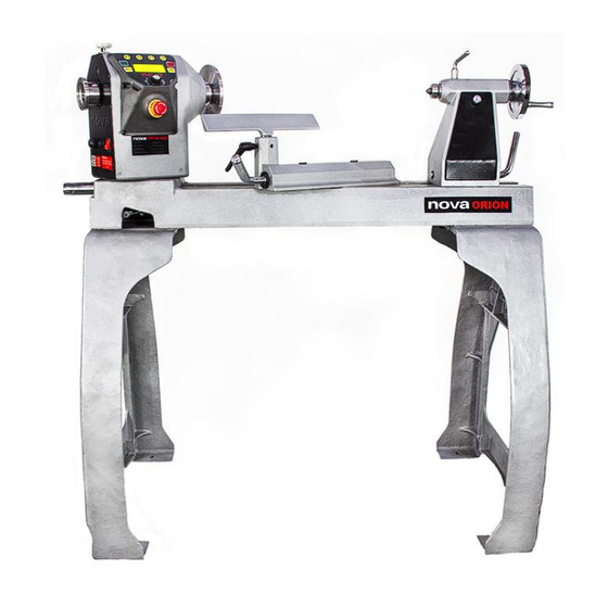
- Page 1 ™ ORION 18” DVR LATHE Publication: 128-1019-004 Models: 55250 – USA 55251 – AUS/ NZ 55252 – EU 55253 – Canada 55254 – UK Date: 10 October 2019 128-1019-004...
-
Page 2: Contact
Contact Teknatool International Ltd Phone: (+64) 9 477 5600 Teknatool USA Phone: 727-954-3433 Customer Solutions For all worldwide Inquiries, Repairs or Services (issues must be in writing) Service@Teknatool.com Email: Or you can contact the retailer where you purchased your NOVA Orion 18” DVR Lathe, for the contact details www.teknatool.com... -
Page 3: Table Of Contents
Firmware Update ..................................... 32 Checking the Firmware Version ................................32 USB Mode ......................................32 Troubleshooting ....................................... 33 Mechanical Issue ....................................33 Electrical Issue ....................................34 Teknatool Warranty ....................................35 NOVA Orion Headstock Breakdown................................. 36 NOVA Orion Lathe Parts List ..................................37 128-1019-004... -
Page 4: General Safety Rules
General Safety Rules WARNING Failure to follow these rules may result in serious personal injury or death. ❖ IMPORTANT: Before switching the lathe on, ALWAYS check the machine for the correct setting and speed BEFORE OPERATING THE TOOL READ THE KEEP GUARDS IN PLACE and in working order. -
Page 5: Nova Orion 18" Dvr Features
NOVA ORION 18” DVR FEATURES Feature Name Description The DVR motor uses smart motor technology to provide an incredibly smooth and powerful drive. DIGITAL VARIABLE The controller constantly monitors the spindle RELUCTANCE (DVR) position and maintains optimal spindle speed. ELECTRONIC DRIVE Additional power is added as it senses extra load from the tool. -
Page 6: Lathe Specifications
Lathe Specifications Metric Imperial 457.2mm 18” Swing Over Bed 560mm / 1120mm 22” / 44” Distance Between Centres 1800mm (L) x 600mm (w) x 1240mm(H) 78.7” (L) x 26.6” (w) x 48.82” (H) Overall Size 210 Kg 460 lb Weight Headstock M33 x 3.5 RH* 1.25”... -
Page 7: Package Contents
Package Contents ITEM NUMBERS DESCRIPTION Headstock Assembly (+HMI) 5699001 + 5699005 Tool Slide Assembly 5699004 Tailstock Assembly 5699033 Main Bed 5699021 Bed Extension* 5699035 Lathe stand 5699018 12” (300mm) Tool Rest 5699024 Knockout/Operating Bar 5699033 2MT Spur Centre 2MTSPUR 2MT Live Centre 5020 6”... -
Page 8: Assembling The Lathe
Assembling the Lathe Connecting Lathe Bed Sections Place the lathe bed onto a leveled surface with a 24mm thick block of wood or anything similar. Connect the main bed and extension bed section together but using the bolts ASSEMBLY NOTE Spring Washer Bolt... -
Page 9: Attaching The Headstock Onto The Bed
Align the lathe bed mounting holes with the slots on the stand legs before inserting the bolts. Make sure the bed side edge matches the machined surface edge of the stand Attaching the Headstock onto the Bed SAFETY CAUTION: The headstock unit itself has a significant mass (Approximately 50Kg) therefore extreme caution must be taken to lift the headstock up to a height where it can be attached to the bed. -
Page 10: Locking The Headstock Into Place
Secure the headstock onto the lathe bed by using the 8mm flat wide washer and M8 hex head bolt included in the packaging. Insert the bolt and washer from underneath the stand through the hole and thread the bolt onto the headstock centre pin. ➢... -
Page 11: Attaching The Tool Rest Onto The Bed
Attaching the Tool Rest onto the Bed Attaching the tool rest onto the tool slide Loosen the tool rest lock handle and Slide the tool rest assembly onto the bed by matching the tool slide lock plate ensure nothing is inside the tool slide with the cut out made on the side of the lathe bed sections. -
Page 12: Nova Orion Bed Configuration
NOVA ORION Bed Configuration Multiple configurations to suit unique size needs Basic Configuration EU/World Standard Bed Accessory Extension (5699035) Available for additional purchase ❖ Center to Center Distance Metric Imperial 558.8mm 22” Basic Configuration with Bed Extension Center to Center Distance Metric Imperial 44”... -
Page 13: Connecting To Power
Connecting to Power Warning! Improper power connection may result in a risk of electrical hazard. Before plugging the NOVA Orion lathe into the power source: 1. The main power switch is turned off 2. Power source is switched off Make sure the “O” side of the rocker switch is pressed in before connecting the power cable to the power source. -
Page 14: Ground Fault Interrupters (Gfi)
Ground Fault Interrupters (GFI) For a GFI to be compatible with the DVR motor, it must have a leak current threshold rating of 30mA (0.03A) ➢ Note: Normal household GFI will typically be rated at 5mA (0.005A) which may trigger during the operation of the DVR motor. However, frequent tripping of the GFI will not cause any harm to the DVR motor or its control electronics as it has a built-in protective circuit to prevent damage from frequent switching. -
Page 15: Lathe Interface
3. Electrical The NOVA Orion lathe requires an appropriate power outlet nearby to power the motor. The outlet wiring must meet the local electrical safety standards. If in any doubt, seek advice from an electrician. The length of an extension cable should be reduced as must as possible. 4. -
Page 16: Operating The Lathe
▪ Forward and reverse state ▪ The second set of favourite speeds will not be ▪ Current state of the lathe displayed. ▪ When the motor is off, set RPM of the lathe. This will change to the actual RPM of the lathe spindle when the motor is turned on. -
Page 17: Stopping The Lathe
Stopping the Lathe Press the <OFF> key while on the home screen to stop the motor. The motor 2 types of behaviours when the <OFF> key is pressed: • Motor stops and no brakes applied • Motor stops and brakes are applied Emergency Stop Switch The emergency stop switch can be pressed to stop the motor any time during operation. -
Page 18: Adjusting The Speed
Adjusting the Speed Set speed of the lathe motor can be adjusted anytime while the HMI is on the home screen. The set speed can be adjusted by turning the speed adjustment knob. Input Set Speed Function The input set speed function allows to quickly set the lathe to any speed within 5rpm by using the function <F#>... -
Page 19: Favourite Speed Function
5. Customize F Keys 6. Lathe Settings 7. Wireless remote 8. Motor Parameters 9. Password Lock 10. Firmware Upgrade 11. Version Info Each function in the menu will be described in detail in the later section of this manual. Favourite Speed Function Favourite speed function allocates pre-set speed to each of the function keys (<F>... - Page 20 After pressing one of the <F> key to change the lathe speed, the lathe screen will change a screen where it asks for conformation to change the lathe set speed. Press<F/R> key to confirm and change the lathe to the speed allocated to the favourite speed.
-
Page 21: Using The Lathe Speed Chart
After pressing the speed control knob on the selected favourite speed, the screen will change to enter the new lathe speed to assign. Both <F> key and speed control knobs can be used to adjust the new speed value. Effect +100rpm -100rpm +5rpm... -
Page 22: Changing The Home Screen Display Mode
The lathe will prompt to select the approximate diameter of the workpiece. The lathe will automatically suggest the recommended speed for the operation. ➢ Note: The speed shown on the lathe is only a recommendation/ guideline. Actual required lathe speed must be determined from the actual condition along with the experience of the turner. -
Page 23: Switching Between Forward And Reverse
Switching between forward and reverse While on the lathe home screen, press <F/R> key to switch between forward and reverse. ➢ Note: The lathe motor must be turned off in order to switch between forward and reverse. Forward and reverse cannot be switched while the lathe motor is running. -
Page 24: Using The Lathe Spindle Lock
Using the Lathe Spindle Lock The NOVA Orion lathe features 24 spindle indexing position which can also be used as a lock spindle lock. Engaging/Disengaging the Spindle Lock Pull the spindle index pin out from the headstock and turn it 180 degrees so the “Lock” text is closer to the HMI. Slowly release the spindle index pin to let the spring pull the index pin into the headstock. -
Page 25: Swivelling The Headstock
Swivelling the Headstock Loosen the headstock lock pin to free headstock. ➢ Note: Use the operating bar to provide more leverage then loosening the headstock lock pin as it can become tighter over time. Push the detent lever towards the right-hand side and hold it in position. -
Page 26: Changing The
Retighten the headstock locking pin to ensure the headstock is securely locked Changing the <F> Key Functionalities Press the <Menu> key to enter the lathe main menu of the lathe Navigate down to “Customize F keys” on the second page using the speed dial. Press in the speed dial to enter the function.Key Functionalities - Page 27 User Custom Settings Functions other than Favourite Speed and Speed Up/ Down can be assigned to the F keys through “User Custom” settings. Press the speed knob when the cursor on the left-hand side is in line with “Edit User Custom” text to enter the function assignment screen.
-
Page 28: Wireless Remote
Wireless Remote The standard NOVA DVR Wireless Remote II (SKU 55522) can be used with the NOVA Orion lathe (Refer to Appendix XX for installation procedures). Once the remote receiver is installed on the lathe: • Navigate down to “Wireless Remote” function in the lathe main menu. -
Page 29: Password Lock
Password Lock Setting the password • Enter the lathe menu and navigate down to “Set Password” on the second page. • Press the speed dial when the cursor is in line with the “Set Password” text. • The screen will change to a screen to enter the new password for the lathe. -
Page 30: Lathe Settings
Clearing the password The password can be cleared from the system by entering the “Clear Password” function. This will clear the password stored in the system Lathe Settings The lathe setting will contain the toggles for the following functions: 1. Assisted Brake 2. -
Page 31: Maintaining Your Lathe
Maintaining Your Lathe WARNING Improper power connection may result in a risk of electrical hazard Regular maintenances are essential when considering the long-term use of the lathe. Maintenance after each use 1. Clean the work area and lathe 2. Vacuum shavings and dust from the headstock, table and base Monthly maintenance 1. -
Page 32: Firmware Update
The firmware version of the HMI can be upgraded via the included USB cable accessory and a PC with internet access. Be sure to check https://www.teknatool.com/upgrade-your-firmware/ periodically for firmware upgrades for your machine, which may allow new features or software improvements that could enhance the performance of the lathe. -
Page 33: Troubleshooting
Troubleshooting Mechanical Issue SYMPTOM PLACE TO CHECK HOW TO RESOLVE 1. Remove any work pieces/tools attached to the headstock, inspect if there is any foreign materials or damages to the threads. ▪ Work attached to the lathe 2. Attach the tools one at a time to check which part is Excessive Vibration ▪... -
Page 34: Electrical Issue
2. Turn off the headstock main power switch and leave it Headstock body to cool down for a period of time. Restart the headstock after it has cooled down. Please contact our customer service team as service@teknatool.com if the above procedures did not resolve your issue. 128-1019-004... -
Page 35: Teknatool Warranty
Teknatool reserves the right to require defective parts be returned upon request. You must plan with Teknatool to schedule the transportation of the parts from your home to the retailer or from the retailer to your home. A RETURN AUTHORIZATION (RA) form will be sent to you via email. -
Page 36: Nova Orion Headstock Breakdown
NOVA Orion Headstock Breakdown 128-1019-004... -
Page 37: Nova Orion Lathe Parts List
NOVA Orion Lathe Parts List ITEM ITEM DESCRIPTION QTY. DESCRIPTION QTY. Headstock Assembly 5699001 2.19 Tailstock Cam Follower 5699048 NOVA Orion Tailstock Alignment Plate 5699050 5699015 Headstock Casting Tailstock Alignment 2.21 BHC0816 EMI Filter 55170 Plate Screw 6207 Bearing 6207ZZ Tailstock Alignment 2.22 FW08... - Page 38 Due to NOVA’s continuous product improvement and development policy, specifications, features and images contained in this manual may change without notice. Teknatool is not responsible for omissions or errors herein, or for incidental damages in connection with the furnishing of this information.
Need help?
Do you have a question about the nova ORION Series and is the answer not in the manual?
Questions and answers