Table of Contents
Advertisement
Quick Links
Advertisement
Table of Contents

Related Manuals for Teknatool Neptune DVR 15


Summary of Contents for Teknatool Neptune DVR 15
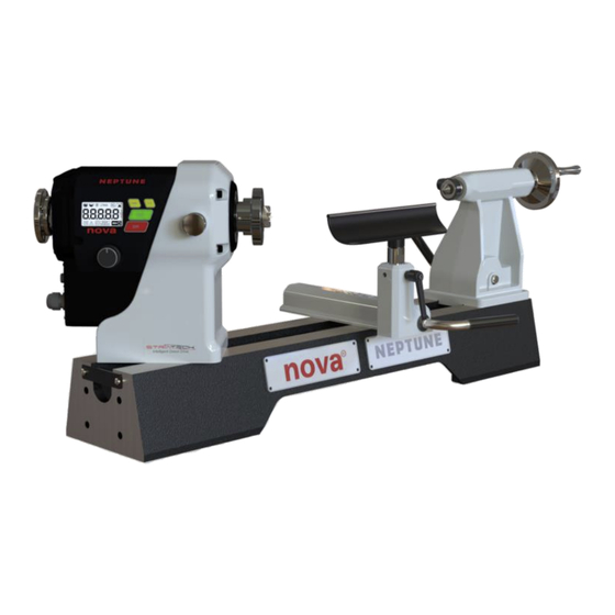
- Page 1 Neptune DVR 15” Lathe USA & Canada SKU: 55700 New Zealand & Australia SKU: 55701 UK SKU: 55702 Europe SKU: 55703 Neptune Max DVR 15” Lathe USA& Canada SKU: 55710 New Zealand & Australia SKU: 55711 UK SKU: 55712 Europe SKU: 55713...
-
Page 2: Contact
For all worldwide Inquiries, Repairs or Services (issues must be in writing) Contact us at: https://www.teknatool.com/support/ Or you can contact the retailer where you purchased your NOVA Neptune DVR 15” DVR Lathe, for contact details please see our website www.teknatool.com... -
Page 3: Table Of Contents
6.1 HMI introduction ............................27 6.2 General HMI Operations ..........................28 7. Maintenance ..................................34 8. Troubleshooting ................................35 9. Teknatool Warranty ................................. 36 10. NOVA DVR Lathe Breakdown ............................37 11. Optional Accessories ..............................43 12.NOVA DVR Wiring Diagram ............................44... -
Page 4: General Safety Rules
1.General Safety Rules WARNING Failure to follow these rules may result in serious personal injury or death. ❖ IMPORTANT: Before switching the lathe on, ALWAYS check the machine for the correct setting and speed BEFORE OPERATING THE TOOL READ THE KEEP GUARDS IN PLACE and in working order. -
Page 5: Nova Neptune/Neptune Max Dvr 15" Dvr Lathe Features & Specification
NOVA Neptune/Neptune Max DVR 15” DVR Lathe Features & Specification Feature Name Description The DVR motor uses smart motor technology to provide an incredibly smooth DIGITAL VARIABLE and powerful direct drive. The controller constantly monitors the spindle RELUCTANCE (DVR) position and maintains optimal spindle speed. Additional power is added as it ELECTRONIC DRIVE senses extra load from the tool. - Page 6 Neptune Lathe Specifications Metric Imperial Swing Over Bed 381 mm 15” Distance Between Centres 457 mm 18” Overall Size 840mm (L) x 425mm (w) x 380mm(H) 33” (L) x 16.7” (w) x 15” (H) Package Size 900mm (L) x 485mm (w) x 440mm (H) 35.4”...
- Page 7 Neptune Max Lathe Specifications Metric Imperial Swing Over Bed 381 mm 15” Distance Between Centres 711 mm 28” 1292mm (L) x 490mm (w) x Overall Size 50.9” (L) x 19.3” (w) x 47.2” (H) 1198mm(H) Package Size Net Weight 95 Kg ± 2 Kg 209lb ±...
-
Page 8: Shipping Contents
3.Shipping Contents Neptune Lathe ITEM NUMBERS DESCRIPTION ITEM NUMBERS DESCRIPTION Headstock Assembly (+HMI) Set Screw M6 x 6mm Toolslide Assembly Soft Washer Tailstock Assembly 2MT Live Centre Main Bed 2MT Spur Centre Bed End Stopper Plate 80mm Face Plate 1 ¼” 8tpi Double Ended Morse Taper –... - Page 9 Neptune Max ITEM NUMBERS DESCRIPTION ITEM NUMBERS DESCRIPTION Headstock Assembly (+HMI) 80mm Face Plate 1 ¼” 8tpi Toolslide Assembly 2MT Spur Centre Tailstock Assembly 2MT Live Centre Double Ended Morse Taper – Main Bed Acruline Alignment Tool Bed End Stopper Plate Foot Assembly Stopper Plate Screws M5 x 6mm Stand Cross Plate...
-
Page 10: Setup And Assembling The Lathe
4.Setup and Assembling the Lathe Workshop Environment Your workshop should be set up appropriately for you to effectively use the lathe. The workshop should be setup with the following factors taken into consideration: Lathe Location Locate the NOVA 15” lathe close to a power source in an area with good amount of lighting. Leave enough clearance when the lathe headstock is swiveled around. -
Page 11: Unpacking And Preparing The Lathe
4.1 Unpacking and Preparing the Lathe 1. Remove all smaller items from the main carton. Do not discard carton or packing material until the lathe is assembled and running satisfactorily. 2. Inspect contents for shipping damage; if any is found, report it to your distributor. 3. - Page 12 Mode 2: Free Standing on Bench with Optional Mounting plates SKU 5529168 This mode is for larger turning work and swivel of the head. The type of turning and size of work pieces up to 12” with good balance and Headstock can be swiveled. It is recommended for any turning work to secure plates to bench with screws or bolts.
- Page 13 Mode 3: Bolt Directly to Bench This mode is for all turning work and outboard turning. The type of turning and size of work piece that is best suited for this mode is up to the limits of the turning in swivel head or outboard turning mode.
-
Page 14: Assembly Bed To Stand (Neptune Max Model)
4.2.2 Assembly Bed to Stand (Neptune Max Model) Step 1: Step 2: Lay the bed face down on a flat clean surface. It is recommended that Align one of the legs with the mounting holes on the bed. Fasten in a piece of cardboard is placed between the bed and the floor to place. -
Page 15: Assemble The Toolrest And Tailstock
Align the cover plate with the holes on the side of the stand. Fasten To balance the stand, adjust the feet accordingly by in place. screwing/unscrewing the feet from the base of the stand. Secure in place by fastening the nut tightly against the base of the leg. 4.2.3 Assemble the Toolrest and Tailstock Assemble the Tailstock Assemble the Toolrest... - Page 16 Note: Turn the lock handle to adjust the position of the lock plate if they cannot slide onto the lathe bed section. 2. Replace stop plates on both ends of bed. Screw end plate into bed to secure headstock onto bed Screw end plate into bed to secure tailstock onto bed 128-01-2310 128-0621-003...
-
Page 17: Positioning The Headstock On The Bed
4.3 Positioning the Headstock on the Bed The headstock uses a cam lock assembly for securing in place along the bed. To move the headstock: 1. To unlock the headstock, push the locking handle backwards or lock the headstock by pushing the handle forwards. -
Page 18: Spindle Index/Lock
4.4 Spindle Index/Lock The spindle index pin locks the headstock spindle. It is selectable in 15-degree increments (24 divisions). An indicator decal is on the rear headstock. 1. Stop the lathe. 2. To lock the spindle, lift up and turn the Locking Knob into the LOCK position until the internal pin engaged into the index fly wheel. -
Page 19: Toolrest
4.5 Toolrest Loosen the Toolslide clamp Handle counterclockwise, move the tool slide to the desired position, and tighten the clamp handle clockwise. Adjust the Toolrest close to the work piece. Exact positioning may be varied to suit the turner. Revolve the stock by hand to make sure it clears the rest before starting the lathe. -
Page 20: Lathe Alignment
4.7 Lathe Alignment Generally, new lathes are strictly inspected in factory and does not need to be aligned again. Over time, as the lathe is used, you may need to re-align your lathe. To realign machine, please follow the method below. Double Ended 2 Morse Taper method: a. - Page 21 d. Slide tailstock to the headstock side of the bed, to firmly align the double ended morse taper with the motor spindle. Lock the tailstock into place. Wind the tailstock handwheel until the motor flange sits securely against the inner ring of the headstock. e.
-
Page 22: Mounting A Faceplate Or A Chuck
4.8 Mounting a Faceplate or a Chuck The thread size of headstock Spindle is 1.25" RH (Standard Version), or M33 RH (Euro Version), depending on your model. 1 ¼” Standard Version Spindle Euro Version Spindle 4.8.1 Mounting on the Standard Version Spindle Make sure there is no gap between faceplate Use the Spindle Index Pin to lock the headstock spindle before commencing. -
Page 23: Mounting On The European Version Spindle
4.8.2 Mounting on the European Version Spindle The diagram below illustrates a cross sectional view of an M33 ASR Eurolock version spindle with an M33 ASR Eurolock chuck mounted. Locking Ring Installation Procedure Step 4 Step 3 Step 2 Use the Spindle Index Pin to lock the headstock spindle before commencing. 128-01-2310 128-0621-003... -
Page 24: Removal Of Faceplate And Handwheel
Step 1: Thread the M33 ASR faceplate or chuck onto the spindle thread all the way in. Check that the spindle and the faceplate/chuck are touching at the clamping ridge. Step 2: Put the lower part of the locking ring under the clamped rings. Step 3: Put the upper part of the locking ring above the clamped rings. -
Page 25: Connecting To Power
5. Connecting to Power Warning! Improper power connection may result in a risk of electrical hazard. Before plugging the NOVA lathe into the power source, check that the: 1. The main power switch is turned off. 2. Power source is switched off. Note: This image on the left-hand side is the European version of the NOVA wood lathe. -
Page 26: Ground Fault Interrupters (Gfi)
5.1 Ground Fault Interrupters (GFI) For a GFI to be compatible with the DVR motor, it is recommended have a leak current threshold rating of 30mA (0.03A) Note: Normal household GFI will typically be rated at 5mA (0.005A) which may trigger during the operation of the DVR motor. -
Page 27: Lathe Operation On Hmi Panel - Human Machine Interface Panel
6. Lathe Operation on HMI Panel - Human Machine Interface Panel 6.1 HMI introduction The Neptune HMI panel consists of four keys, one speed knob for the lathe operation, the 2.4” LCD shows the status of the lathe in real time, these keys and icons on the panel are illustrated as follows. [FUNC]: Access or Exit to the lathe functions. -
Page 28: General Hmi Operations
6.2 General HMI Operations 6.2.1 Start-Up Turn on the switch, the HMI will run the self-test in 3 seconds. During the test, the LCD will show all icons and software version No. before it goes to the Home page. At the home page, the machine is ready to run now, the default speed is 500 RPM. - Page 29 6.3.1 General operation to Enter and Exit FUNC Menu When the LCD is on the Home page, Press [FUNC] once to enter the function page, turn the speed knob clockwise or counter clock wise, the LCD will show all 5 functions in a sequence: Favourite speed->Brake Enabled->Rough cut->Fine cut->...
- Page 30 Favourite Speed Function Page (Flashing) Default Pre-set Speed Programming Mode 6.3.4 Brake Enabled The brake is optional feature to combined with OFF operation, with the brake ON, the motor speed will be deaccelerated quicker than normal (the default setting is OFF). Step1: Press [FUNC] once on the Home page, turn the speed knob to Brake Enabled icon, press [ON] to enter the Brake Enabled page or press [FUNC] or [OFF] to exit.
- Page 31 Step2: At the Rough cut/Fine cut page, turn the speed knob to Diameter options#1-3, small, medium and large size. press [ON] to confirm or press [FUNC] or [OFF] to exit. Rough Cut (Imperial) - Diameter Selection Page Fine Cut (Imperial) - Diameter Selection Page Press [Down &...
- Page 32 XL/Unbalanced Function Page Speed Screen with XL/Unbalanced Mode Engaged 6.4 Miscellaneous 6.4.1 Load monitoring Real time The HMI can show a load factor as reference for turning operation. While the motor is running, press [Down & Hold] the speed knob for 2S, the LCD will show the approximate capacity of the motor being used by turning operation, press [Down &...
- Page 33 Stop the motor first, press [Down & Hold] speed knob +[FUNC] for 3second. The HMI enters the USB mode for firmware upgrade. Download HMI USB/DFU update software and firmware from the website: www. teknatool.com, follow the instructions to upgrade HMI firmware.
-
Page 34: Maintenance
7. Maintenance • WARNING Improper power connection may result in a risk of electrical hazard Regular maintenance is essential when considering the long-term use of the lathe. Maintenance After Each Use 1. Clean the work area and lathe. 2. Vacuum shavings and dust from the headstock, table and base. Monthly Maintenance 1. -
Page 35: Troubleshooting
8. Troubleshooting 8.1 Mechanical Issues SYMPTOM PLACE TO CHECK HOW TO RESOLVE 1. Remove any work pieces/tools attached to the headstock, inspect if there is any foreign materials or damages to the threads. ▪ Work attached to the lathe 2. Attach the tools one at a time to check which part is Excessive Vibration ▪... -
Page 36: Teknatool Warranty
Our policy is one of continuous improvement. We therefore reserve the right to change specification/design without notice. This warranty is Teknatool International Ltd and Teknatool USA Inc. sole warranty whether written or verbal, whether expressed or implied by law, trade, custom, or otherwise, whether of merchantability, fitness for purpose, or otherwise, except for remedies available to customers under the Consumer Guarantees Act or other legislation. -
Page 37: Nova Dvr Lathe Breakdown
10. NOVA DVR Lathe Breakdown NOVA DVR Headstock Breakdown ITEM ITEM DESCRIPTION QTY. DESCRIPTION QTY. Camshaft Set Screw M6x12mm - Headstock Assembly 5529013 Dog Point Headstock Casting 5529127 1.10 Headstock Locking Boss 5529117 Controller Assembly 5529015 / 1.11 Headstock Lock Plate 5529116 (US &... - Page 38 NOVA DVR Tailstock Breakdown ITEM ITEM DESCRIPTION QTY. DESCRIPTION QTY. Tailstock Assembly 5529019 2.10 Tailstock Locking Boss 5569025 Tailstock Casting 5529160 2.11 Tailstock Lock Plate 5569043 Tailstock Quill 5529163 2.12 Quill Alignment Screw SZ0820 Tailstock Quill Lead Screw 5529162 2.13 External Circlip 12mm EC12 Tailstock Handwheel Handle...
- Page 39 NOVA DVR Toolrest Breakdown ITEM ITEM DESCRIPTION QTY. DESCRIPTION QTY. Toolslide Assembly 5529011 Toolrest Post 1 Inch 5529153 Toolslide Casting 5529102 Mounting Screw M6x6mm SZ0606 Toolslide Lock Camshaft 5529103 3.10 Self -Locking Nut 304 Ø 16 LN16 Camshaft Ring 5529104 3.11 Flat Washer M16 FW16...
- Page 40 Neptune Bed Breakdown ITEM ITEM DESCRIPTION QTY. DESCRIPTION QTY. Main Bed Assembly Stopper Plate Screws M5x6mm MPB0506 Main Bed 5529123 “NOVA” Name Plate Feet Assembly 5529145 “NEPTUNE” Name Plate End Stopper Plate 5569059 Name Plate Mounting Screws MPB0305 128-01-2310 128-0621-003...
- Page 41 Neptune Max Bed & Stand Breakdown ITEM ITEM DESCRIPTION QTY. DESCRIPTION QTY. Neptune Max Bed & Stand Stand Cross Plate 5519016 Assembly Main Bed 5519091 5.10 Stand Tool Tray 5519017 Stand Legs Set A 5519015 5.11 Foot Assembly 24161 Stand Legs Set B 5.12 Mounting Screws M12x35mm C12035...
- Page 42 Accessories Breakdown ITEM ITEM DESCRIPTION QTY. DESCRIPTION QTY. Accessories Pack 2MT Spur Centre 2MTSPUR Universal Spanner 5568099 2MT Live Centre 2MTLC Double Ended Morse Taper – 3mm Allen Key 2MTNA Acruline Alignment Tool Knock Out Bar Neptune Manual 80mm Face Plate 1 ¼ 8tpi 5529171 / 10mm Allen Key 6.10...
-
Page 43: Optional Accessories
11. Optional Accessories Emergency Stop Mounting Plate (SKU: 5529173) (SKU: 5529168) Neptune Stand Outrigger (SKU: 5529169) (SKU: 5519001) Bed Extension Neptune Max Stand (SKU: 5529125) (SKU: 5529170) 128-01-2310 128-0621-003... -
Page 44: Nova Dvr Wiring Diagram
12.NOVA DVR Wiring Diagram 128-01-2310 128-0621-003... - Page 45 Due to NOVA’s continuous product improvement and development policy, specifications, features and images contained in this manual may change without notice. Teknatool is not responsible for omissions or errors herein, or for incidental damages in connection with the furnishing of this information.
Need help?
Do you have a question about the Neptune DVR 15 and is the answer not in the manual?
Questions and answers